Multirate Haptic Simulation Achieved by Coupling. Finite Element Meshes through Norton Equivalents. Oliver R. Astley and Vincent Hayward. Department of ...
Multirate Haptic Simulation Achieved by Coupling Finite Element Meshes through Norton Equivalents Oliver R. Astley and Vincent Hayward Department of Electrical Engineering and Center for Intelligent Machines McGill University 3480 University Street, Montr�eal, Qc, H3A 2A7, Canada
�foliver,haywardg/Home.html
http://www.cim.mcgill.ca/
Abstract This paper introduces a methodology to simulate the dynamics of deformable visco-elastic 3-dimensional bodies in real-time for haptic interaction. The method is based upon a nite element approach. The central idea in this scheme is to reduce the computation required in regions which are to the periphery of the region of interaction between the virtual haptic device and the virtual body. This is accomplished by implementing a multi-layer nite element mesh. The top layer, or parent, consists of a coarse mesh of the entire body; child meshes represent sub-regions of the coarse mesh, but have a much ner resolution. By using equivalent impedances to relate the two meshes, it is possible to decouple the coarse and ne regions; this enables the system to not only to have di�erent resolutions in di�erent regions, but also allows the parent and child meshes to be updated at di�erent frequencies. The multi-layer mesh also addresses numerical integration issues.
1 Introduction A platform for deformable body haptic interaction must consider the multi-faceted constraints and objectives (both present and future) inherent to haptic simulation. As such, the system should be designed with issues such as computation reduction, numerical integration stability, the human user, and system
exibility in mind from the outset. Importantly, the system must be scalable, such that it will be able to accommodate other tasks in the future, for example, virtual cutting in surgical simulation. The approach presented in this paper considers all these issues. In particular, reducing redundancies in computations, and
reducing calculations which have a minimal e�ect on the system and the user. The advance in computer power with respect to cost has made the interactive simulation of three dimensional deformable bodies feasible. This is re ected in current research focussed on performing these tasks in real-time. Nevertheless, the numerical complexity of these simulations require that some form of \numerical compression" is applied to achieve reasonable simulation update rates. Examples of using numerical compression are numerous. Cover et al. [4], for example, elect not to use a nite element approach due to its data density and adopt an energy surface instead. Many of the modeling issues in deforming solids have been addressed by Terzopoulos [9] and then applied to nite element systems in [8]. Cotin et al. [3] have integrated a nite element system with haptic feedback in real-time. They have used linearity principles and thresholding to reduce on-line computations. As yet their system has not implemented damping and inertia. These approaches have not considered the need for accuracy enhancement close to the region of interaction between the virtual device and the deformable body. Similarly, in areas to the periphery of the interaction region, less detail and accuracy is required in the simulation, and hence numerical compression opportunities exist. A standard nite element method to achieve accuracy enhancement is adaptive meshing [1]. Existing adaptive meshing techniques are not suitable for the purposes of real-time interaction because, for three dimensional bodies, they are too CPU intensive for online use and, in general, cannot guarantee an upper bound on completion time, a necessary requirement of real-time systems. This paper presents a nite element based method which decouples the body to be
modelled into a hierarchical mesh structure consisting of high and low density regions. A top layer (parent) coarse mesh models the entire body, and several second layer ne meshes model sub-regions of the body. By decoupling the mesh into separate nite element systems, di�erent regions of the mesh can be computed at di�erent rates, while simultaneously ful lling the goal of reducing computation in areas to the periphery of direct interaction. As the region of interaction moves with the input device, the higher density meshes are activated and deactivated as required. Importantly, most of the overhead for the multi-layered mesh is incurred during pre-processing.
2 Constraints and Assumptions The goal of this research is to simulate deformable bodies and facilitate interaction using a haptic device. It is therefore necessary, during the design process, to comprehend the constraints imposed by the human user as well as the available hardware.
2.1 Human Factors Understanding human bandwidth constraints is essential when designing interactive systems, three pertinent ones are: 1. Humans can sense force vibrations well in excess of 300Hz [5, 6]. 2. An update rate in the range of 20-40Hz is preferred for the visual feedback rendered using computer graphics. 3. The maximum human force of motion output bandwidth is 10Hz, although in general the output is in the region of 1 or 2Hz [5]. Designing a system which solely runs at the highest target frequency of 500Hz would be over designed. (If it was indeed computationally possible.) This indicates that to e�ciently distribute the computational load, a system will have components running at different rates. For example, at the haptic output higher rates are required compared to visual update rates. To avoid processing system components which will be e�ectively ltered out by the human sensory system, a multirate approach has been adopted in this work.
2.2 Deformable Body Properties The neighbourhood of interest is de ned as the region surrounding the point of interaction between the
virtual tool and the deformable body. The neighbourhood of interest should be simulated as accurately as is computationally possible, i.e. within the haptic time constraints. To the periphery of the region of interest, neither the eye, nor the dynamic simulation calculations, require such a high accuracy or such a fast update rate. Therefore an accuracy for computation reduction tradeo� exists. This tradeo� has the potential of reducing the required CPU load tremendously|a necessary factor for real-time interaction.
2.3 General Hardware Constraints From the outset it was decided not to simply \throw" multiple processors at the real-time dynamic simulation problem. Rather, a reduction of the per cycle processing is sought. The hardware which the following work is implemented on is as follows: � A single processor R10000 Silicon Graphics IMPACT computer. This is used for the dynamic simulation and graphics display. � A Pentium processor used for low level control of the haptic device. � A 7 D.O.F. force feedback hand-controller [7]. Somewhat ironically the algorithm to be presented is also conducive to a multi-processor environment, but as yet, we are using just one processor.
3 Introducing the Multi-Layer Mesh The following meshing approximation is proposed which circumvents the problems found in traditional adaptive meshing systems, and ful ls the goals delineated in the introduction. In brief, the deformable body is modelled by several nite element meshes organized in a layered hierarchy. For example a two layer mesh consists of one top layer coarse mesh, and several ner meshes which are subsets of the coarse mesh. At anyone time, just one second layer mesh is active; the activated mesh will generally be chosen based on its proximity to the virtual tool. A lower level mesh is physically linked to its higher level mesh parent through equivalent impedances. By explicitly splitting the mesh into several layers the following objectives are achieved: � The neighbourhood of interest is modelled by a ner mesh, while regions to the periphery are considered only by the coarser mesh. This means
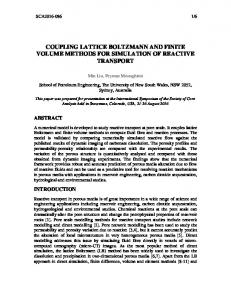
Neighbourhood of Interest
Uf2
Uf2 Uf1
Uf1
Uf3
Uf3 Uf4
Uf4
(a) Body at Rest
(c) Neighbourhood of Interest -- Fine Mesh (One sub-region in second layer)
(b) Coarse Mesh (Top layer)
Figure 1: Modelling a Deformable 2D Body { A coarse mesh is applied to entire body, this is the top layer or parent mesh. The second layer is made up of several sub-regions of the body, one such region is highlighted in (b) and then meshed in (c).
�
�
�
that regions of the mesh undergoing less change will be resolved at lower resolutions. The coarse mesh is generated such that bounds on the minimum accuracy of the solution away from the neighbourhood of interest are met, especially in high stress/strain regions. The two systems, although computationally coupled, can be simulated independently and at different rates. This allows the ne mesh, which is the region of principle interest, to be solved at the fastest rate, while the coarser mesh is solved at a slower rate. The majority of the workload in the two layer mesh system can be done in pre-processing, rather than on-line, this frees up valuable CPU time. Although nite element systems are currently being used in both layers, the equivalent impedance could be used to relate two very di�erent computational processes. For example the second layer could implement a cutting, a needle penetration, or another ne phenomenon simulation unit.
manner in Figure 1.b. Finer (second layer) meshes are then de ned based on the general structure of the coarse mesh. For example two coarse elements in Figure 1.b have been chosen to de ne one ne mesh region. An exploded view of this region is shown in Figure 1.c with the ne meshing complete. The next task is to join these two regions such that the coarse and ne mesh are computationally coupled.
3.2 Coupling the Two Meshes Using an electrical analogy, the concept for coupling the two meshes can be found in any basic electronic circuit text|that of the Thevenin or Norton equivalent [2]. In linear network analysis it is frequently desired to nd the voltages and currents of just part of a large circuit, the part which is not of direct interest can be replaced by a simpler equivalent. This equivalent consists of a voltage or current source and an impedance as shown in Figure 2.
The mechanisms involved in the system are now described.
NETWORK 1
3.1 Mesh Description In this section the multi-layer mesh is described using a two layer mesh in two dimensions. The concept is scalable to an arbitrary number of layers and to three dimensions. (The current implementation has been written for three dimensional bodies.) Figure 1.a shows an arbitrary body at rest. It is segmented into the top layer coarse mesh in the usual
NETWORK 2 (a)
Equiv. Force
Equiv. Imped
NETWORK 2
(b)
Figure 2: The Norton Equivalent Network Theory
Using displacement and force as mechanical analogs for voltage and current, the equivalent impedance concept is applied to the two layer mesh as shown in Figure 3. The ne and coarse meshes share some nodes; these are labelled Uf1, Uf2, Uf3, and Uf4 in the Figures. The task is to nd the impedance at these common nodes. The impedance is calculated from the mesh elements surrounding the region of interest at the coarse mesh level. It is important that the equivalent impedance calculation at the coarse level does not include the region of interest (the shaded region in Figure 1.b) because this region is explicitly modelled in the ne mesh using regular meshing techniques. Once the equivalent impedances are found for each common node, they are augmented to the ne (second level) mesh as shown in Figure 3. The calculation of the equivalent impedance for a given common node i is carried out as follows. The nite element system at the coarse (top level) mesh is given as:
Kc u
=F (1) Since only the coarse mesh elements, which are not in the region of interaction, are required for the equivalent impedance calculation, the contribution of the coarse elements in the region of interest (the region which the ne mesh represents) is subtracted from the system. Giving K�c . This process can be visualised as cutting out the region of interest in the coarse mesh, and then nding the equivalent impedance at points in the remaining mesh. The equivalent impedance at node i can be found by applying an arbitrary force f to node i. Currently, for the equivalent impedance calculation, we approximate the relationship between the force applied at node i in direction x and the its corresponding displacement in direction x to a scalar one. Therefore, when the system K�c u = F j = is solved, the equivalent impedance is: c
c
c
Fi
Keq = ;i
f
f u
c;i
(2)
This impedance is then augmented to the ne mesh system Kf u = F . This technique can be extended to equivalent damping and inertia. The multi-layer mesh creation, the equivalent impedances, and the generation of the sti�ness, damping, and inertia matrices can be done o�-line in preprocessing. Due to the increased granularity of the ne mesh, there exists nodes along the coarse- ne mesh boundary f
f
which are not shared by the two mesh layers. These nodes are shown on Figure 3. Although elements of arbitrary order can be used, for the purpose of this example, consider that all elements are linear. On the boundary between Uf2 and Uf1 there exists a one piece linear segment on the coarse mesh side, and a piecewise linear segments on the ne mesh side. To enforce conformity along this boundary, the nodes within the ne mesh which lie on the boundary are restricted to the linear segment de ned by the coarse mesh. That is, Shared Node Position = a1 Uf1 + a2 Uf2 (3) The nite element framework enables enforcement of boundary node conditions of this type linearly for elements of arbitrary order. Node constraints, such as (3), reduce the order of the dynamic matrices, but also cause a loss of matrix symmetry. In systems using explicit numerical integration, the loss of symmetry does not e�ect the solution approach because symmetric methods, such as conjugate gradient solvers, are not required. There is, however, some loss in processing time caused by the reduction of memory cache hits due to the added storage requirement. In the event that the body is stimulated by sources other than the haptic device, then equivalent forces can be augmented to the second layer model, marked Feq1, Feq2, Feq3, and Feq4 in Figure 3. (An example would be a heartbeat in a medical simulation.) The equivalent force can be found in a number of ways. One method is to apply the force to the coarse mesh system, K�c u = F , and solve for u . The equivalent force at shared node i is given by: c
c
c
Feq = Keq u ;i
;i
c;i
(4)
3.3 Process Flow By decoupling the mesh into a ne and coarse regions it is possible to solve each mesh independently and at di�erent frequencies. At present, the system is con gured such that the activated second layer mesh is solved ten times for each time the top layer mesh is solved. Each time the coarse mesh has completed its calculations the system checks to see which second layer mesh should be activated. This is based on the position of the haptic device in the virtual world. The parent mesh experiences the e�ects of the interaction between the child mesh and the virtual device through the displacement of the common nodes shared between the two layers.
Keq2 Feq2
Non-Shared Nodes only exist in fine mesh representation
Feq1
Keq1
Uf2 Uf1
Keq3
Feq3
Shared Node exists in both fine and coarse mesh representations
Uf3
Equivalent impedance as seen from Uf4 Keq4 in the coarse mesh
Uf4 Feq4
Figure 3: Application of the Norton Equivalent to the Fine Mesh.
4 Implementation Results
5 Discussion and Future Work
Currently the system is being implemented using cubic, quadratic, and linear brick elements. Brick elements have been used because they are easy to mesh during this proof of concept stage. Initial testing shows that using a 1000 node cubic coarse mesh with a 1500 node cubic ne mesh, update rates of over 10Hz can be achieved for the ne mesh, while the coarse mesh is running at 1Hz. The simulation implements sti�ness, damping, and inertia. The inertia matrix is lumped, as outlined in Zienkiewicz [10], to a diagonal matrix. This makes inverting the inertia matrix straightforward. Clearly this introduces another approximation, the e�ect of which is being studied. The performance obtained above was achieved using 2nd order explicit numerical integrators. We have focussed on explicit numerical integrators because future applications which involve altering the simulated dynamic body, such as cutting in surgical simulation, we feel, will prove computationally too expensive if implicit integration is used. Currently we are negotiating several problems with regard to the overall haptic interaction, these are: � Collision detection between the device and the deformable body. � Numerical integration stability. � Generating a simple model to execute at rates in the region of 500Hz for a smooth force rendering on the haptic device.
This paper has introduced a method to simulate a deformable body with mass, damping, and sti�ness. The design methodology is based around three concepts. �
�
�
Regions to the periphery of the point of interaction between the device and the deformable body require less detail and numerical accuracy than regions close to the point of interaction. The ability to decouple the mesh into di�erent layers, based on node density, allows di�erent regions of the mesh to be executed at di�erent rates, giving priority to regions of greater interest. In the future, algorithms for cutting virtual tissue may require methods which do not involve nite elements; yet, in regions away from the cut, the mass, damping, and sti�ness e�ects are still pertinent. Using the concept of equivalent sti�nesses, damping, and inertia, two very di�erent operational processes can be coupled. For example, a cutting process and a nite elements process.
What is more, although not an original goal of this research, this method can be seamlessly implemented on several processors for additional speed up. A key feature of this mesh architecture is the effect the hierarchical mesh has on numerical integration. For a given set of material properties, it can be shown that the smaller the nite element, the larger
the eigenvalue magnitudes become, and hence the dynamic system becomes sti�er. As the magnitude of the eigenvalues increase, either a smaller time step, or a higher order numerical integrator must be used to ensure numerical stability. In the former case, a decrease in the mesh complexity to reduce calculations is required to allow a shorter time step. In the latter case, a higher order numerical integrator will require extra function evaluations, thus increasing the time step size possible in real-time. By utilising a coarse mesh, the eigenvalue magnitude and computation requirement can be kept lower, thus allowing slower update rates and/or lower order numerical integrators. Since the ne mesh is used in only a subset of the coarse mesh region, much fewer nodes are necessary within the ne mesh process compared to using the same granularity over the entire region; this allows an increase in the update rate necessary for the larger magnitude eigenvalues ner approximations bring. A hierarchical mesh structure lends itself naturally to collision detection between the virtual body and the device. The low density top layer mesh is scanned rst, this indicates which second layer mesh (sub-region of the body) to check for a collision. Currently we are working on, from a theoretical and experimental perspective, the a�ect of the multi-layer mesh on accuracy, stability, and convergence, when compared with that of a normal nite element system. In the future, we intend to add a more complete interface for the haptic device. It is intended to utilise and implement current haptics research within this study. For example perceptual phenomena sometimes known as \haptic illusions" will prove useful in making simulations both more realistic while also a�ording the opportunity to reduce computational load as well.
6 Acknowledgements Funding for this research is provided by the project \Haptic Devices for Teleoperation and Virtual Environments" (HMI-6) supported by IRIS (Phase 2), the Institute for Robotics and Intelligent Systems part of Canada's National Centres of Excellence program (NCE). Additional funding is provided by NSERC, the National Science and Engineering Council of Canada, in the form of a postgraduate scholarship for the rst author and an operating grant \High performance robotic devices" for the second. The rst author also receives funding from a Raychem Cooperation Paul M. Cook International Scholarship.
References [1] I. Babuska, J.E. Flaherty, W.D. Henshaw, J.E. Hopcroft, J.E. Oliger, and T. Tezduyer. Modeling, Mesh Generation, and Adaptive Numerical Methods for Partial Di�erential Equations. Springer-Verlag, 1 edition, 1995. [2] W.K. Chen. Linear Networks and Systems: Algorithms and Computer Implementations. World Scienti c, 1990. [3] S. Cotin, H. Delingette, and N. Ayache. Real time volumetric deformable models for surgery simulation. Visualization in Biomedical Computing, September 1996. [4] S.A. Cover, N.F. Ezquerra, J.F. O'Brien, R. Rowe, T. Gadaxz, and E. Palm. Interactively deformable models for surgery simulation. IEEE Computer Graphics & Applications, 13(6):68{75, November 1993. [5] P. Fischer, R. Daniel, and K.V. Siva. Speci cation and design of input devices for teleoperation. IEEE International Conference on Robotics and Automation, 1:540{545, 1990. [6] V. Hayward. Toward a seven-axis haptic device. IROS '95, IEEE/RJS Int. Conference on Intelligent Robots and Systems, 1995. [7] V. Hayward, P. Gregorio, O. Astley, S. Greenish, M. Doyon, L. Lessard, J. McDougall, I. Sinclair, S. Boelen, X. Chen, J.-P. Demers, J. Poulin, Benguigui I., N. Almey, B. Makuc, and X. Zhang. Freedom-7: A high delity seven axis haptic device with application to surgical training. International Symposium on Experimental Robotics, ISER'97, 1997. June 15{18 1997, Barcelona Spain. [8] McInerney T. and D. Terzopoulos. A nite element model for 3d shape reconstruction and nonrigid motion tracking. IEEE 4th International Conference on Computer Vision, pages 518{523, 1993. [9] D. Terzopoulos and Fleischer K. Modelling inelastic deformations: Viscoelasticity, plasticity, fracture. Computer Graphics, 22(4):269{278, August 1988. [10] O.C. Zienkiewicz. The Finite Element Fourth Edition, volume 1. McGraw-Hill U.K., 4 edition, 1989.