the fingers. Fig. 1 Schematic diagram of the wristband-shaped electrode array .... One is surface connection type (we do not treat this type of sheet in this paper).
PROCEEDINGS OF THE 24TH SENSOR SYMPOSIUM,2007.pp.59∼63
B1-2
Myoelectric Pattern Measurement on a Forearm Based on Two-Dimensional Signal Transmission Technology Yasutoshi Makino* and Hiroyuki Shinoda* Last year, we proposed a new man-machine interface that detects myoelectric signals on a forearm. One of the remarkable aspects of the myoelectric signal is that the signal can be observed just before the limbs movement. Thus, a prediction of the motion of the limbs is possible when a precise observation of the myoelectric potentials is realized. It is considered that a high-density electrode array is necessary for improving the accuracy of the motion estimation. In our previous work, we proposed “Two-Dimensional Communication (TDC)” technology for realizing a dense EMG sensor array system. In the TDC scheme, we need no wires for signal transmission and power supply. Signals and electrical power are transmitted throgh a two dimensional medium to sensor nodes attached on the sheet. In this paper, we show how to send the data to a host machine in the TDC sheet. We adopt a time division multiplexing method for reducing interferences among the sensor units. Keywords: Man-Machine Interface, Electromyography (EMG), Two-Dimensional Communication.
In order to improve the accuracy of the estimations, it is considered to be important to increase a number of measuring points. An increase of the number of the electrodes also causes one considerable issue: an increase of the wires. Due to these wires, the movement of the arm is restricted. Moreover stretchablity of the wristband decreases owing to the inextensible wires. This makes it hard to keep steady contact between the electrodes and the skin surface. There are several previous studies which measures dense 2D Electromyography (EMG) [2] [3], however, these studies assumed some special situations that force wearing such complex devices. Or in some other researches [4] [5], the myoelectric signals are obtained by a few sparse measurement points on the major muscles. They devoted most of their efforts to a pattern matching technique. Initial alignment of the electrodes is important for keeping the same measurement condition. In this paper, we aim to achieve EMG-based man-machine interface that is feasible for daily use. Following three conditions are considered to be desirable for this purpose. 1) There are few wires for data collection so that the arm and fingers can move freely. 2) Precise alignment of the sensors is unnecessary. 3) Comfortably wearable.
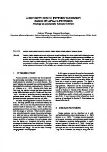
1. INTRODUCTION Last year we proposed a new man-machine interface that was based on Electromyography (EMG) as shown in Fig. 1. The myoelectric signals are electric potentials that produce contraction of the muscle fibers. The signals can be measured with electrodes that are attached on a skin surface. One of the remarkable aspects of the myoelectric signal is that the signal can be observed just before the limbs movement. Therefore, a prediction of the motion of the limbs is possible when a precise observation of the myoelectric potentials is realized. In our system, we focused on the prediction of finger motions. It is known that almost all the muscles which cause the finger movements exist in the forearm. Muscle contractions in the forearm are converted into finger movements through tendons. Consequently, precise two dimensional EMG data on the forearm enables one to estimate finger motions without any constraints on the fingers.
In order to achieve these conditions, you can use wireless communication instead of the wires, however, a large number of batteries are required for each sensor unit. You also need to worry about interferences among the sensor units and with the outside devices. “Two Dimensional Communication (TDC)” technology can be one solution for satisfying these requirements. In the TDC technology, signals are transmitted within a two dimensional medium (TDC sheet) as well as an electric power by microwave. The sensors attached onto the TDC sheet can communicate with each other without any wires. The electrical power is also supplied through the sheet. Each sensor needs no battery. Therefore, the sheet can be used as substitutions for the individual wires or for the wireless communication. Note that this technology corre-
Fig. 1 Schematic diagram of the wristband-shaped electrode array for electromyography [1]. * Department of Information Physics and Computing. Graduate School of Information Physics and Technology, the University of Tokyo. 7-3-1, Hongo, Bunkyo-ku, Tokyo, Japan 113-8656
59
figuration of the communication sheet is quite simple. The sheet consists of three layers. Two conductive layers sandwich the dielectric layer. We theoretically showed that a propagation mode exists in the sheet when a high frequency alternate voltage is impressed between the two layers. The theory shows that the frequency must be high enough so that the corresponding wave length λ is smaller than the sheet size. For example, 2.4 GHz microwave, whose wavelength λ is about 10 cm, (which is usually used in the wireless communication protocols) propagates within the dielectric layer if the sheet size is assumed to be 30 cm x 30 cm. In this propagation mode, the energy is confined within the sheet. It does not interfere with outside devices. Since a higher power microwave can be applied without worrying about interferences, we can supply enough electric power to the sensor units with microwave as well as a signal transmission. Two types of communication sheet were proposed previously. One is surface connection type (we do not treat this type of sheet in this paper). This type of the communication sheet enables one to connect devices anywhere on the sheet without electrical contact [13]. To achieve this performance, one conductive layer of the sheet has lattice structure. The connector size for the surface connection is about 6 cm in diameter at 2.4 GHz. On the other hand, the other type of the sheet is embedding type of the communication sheet. Figure 2 shows the basic configuration of the embedding type of the TDC sheet. There are connection apertures on the sheet surface. The devices can be connected to the sheet through the connection aperture. Though the connecting point is restricted in this type of connection, the size of the connector can be reduced than that of the surface type. For effective coupling between the sensor and the embedding type of the sheet, we proposed a connector named “Resonant Proximity Connector (RPC)” last year [12]. When the total length of the electrode is designed to be λ/4 of the microwave, the connection can be seen as a short owing to its resonance. A notable characteristic is that it requires no electrical contact between them. The connection apertures can be covered with a thin insulating material so as to prevent the conductive materials from oxidization. We also confirmed that the size of the RPC could be reduced down to about 3 mm in diameter by curling its shape. This connector is suitable for realizing a high density sensor array. Since the connector requires no rigid connection to the sheet, the system is durable and stretchable even when the large number of the sensor units is mounted. Moreover, when the electric power is supplied through the RPC, the common potential of the sensor unit can be isolated to the ground potential. This advantage is useful for reducing common mode noises as shown in next section.
sponds to the physical layer of the OSI reference model. Any communication protocols such as IEEE802.11a/b/g, Bluetooth and etc. are available for high speed communication. Since the signals do not propagate to the outside of the sheet, no interference with outside devices occurs. When the sheet is fabricated like a wrist-band shape as shown in Fig.1, the EMG data is obtained as two dimensional patterns. The system requires no specific alignment for measurement. One of the notable characteristics in the TDC is that the communication sheet can be realized with conductive flexible materials including conductive fabrics, conductive rubbers, and so on. It enables us to wear the measurement system comfortably. The stretchability also ensures the steady contact between the electrodes and the skin surface. The contact impedance between them can be decreased. Traditional wiring technologies including a flexible substrate can not be used for realizing such a high-density-sensor-embedding in a stretchable sheet. Because of the features mentioned above, following two practical advantages are expected. 1) Intuitive data input by natural finger motions is possible. 2) Response delays are reduced (no irritations). Thus, it is promised that following applications are achievable. • An input interface for small devices such as mobile p hones or PDAs. • Operating artificial limbs. • Inputting commands by one’s behaviors for video gam es and etc. • Recording behaviors of athletes by the myoelectric sig nals. The stored data are useful to know the motions and to teach the motions. In our previous paper [6], we theoretically and experimentally showed that our sensing system could reduce common mode noises. Since the sensor units need no electrical contact to the TDC sheet, the unit can be driven being isolated from the ground potential. In this paper, we show how to send the data to a host machine in the TDC sheet. We adopt a time division multiplexing (TDM) method for reducing interferences between the sensor units. In our method, there are two stages. One is for power supply to every sensor on the sheet; the other is the stage for sequential signal transmission. Measured data is transmitted by PWM method with low power consuming electric circuit. We demonstrate that the PWM can be achieved by our proposed circuit and that the signal can be received at the side of the sheet. In the next section we show a principle of the “Two Dimensional Communication” technology. In section 3, we briefly describe how to reduce common mode noises. Then we show the way to send data from the sensor units to a host machine with small power consumption in section 4.
2. TWO DIMENSIONAL COMMUNICATION The idea of communication using two dimensional medium was originally proposed by some research groups [8], [9], [10] including us [7] at the early 2000s. In the researches [8], [9] and [10], however, high speed communication through the medium was out of consideration. In addition, mechanical and electrical contacts of elements to the conductive layers were necessary. “Two Dimensional Communication (TDC)” was reported by Makino et al. in [11] as a substitution for the wires. Basic con-
Conductive layer
Connection aperture
Dielectric layer Fig. 2 Schematic illustration of the of the Two-Dimensional Communication descrived in [11]
60
Any materials with high conductivity are available as the conductive layers like conductive fabrics and conductive rubbers. The sheet is feasible for the comfortably wearable wristband shaped man-machine interface.
3. MYOELECTRIC POTENTIAL MEASUREMENT A myoelectric signal is the signal that produces muscle contraction. The signal is observed by electrodes attached on the skin surface with its voltage is order of several mV. As a result, reducing a common mode noise is one of the important issues for the EMG. However, if the measurement circuit is isolated from the ground potential, we are released from consideration about the common mode noise. In our TDC system, the sensor unit is connected to the sheet through a small capacitor (RPC) whose capacitance is as small as 1 pF. Thus, the connection to the ground potential is negligible. Figure 3 shows an equivalent circuit of our proposed method [6]. The point of the circuit is that the common potential of the measurement circuit Va. is isolated from the ground potential (weakly connected through the 1 pF capacitor). This makes the all the potential on the circuit float. The common mode noise can be reduced by instrumentation amplifier. In our former paper, we demonstrated that the myoelectric signals can be detected by these two-electrodes based measurement system. Figure 4 and 5 show the results in [6]. In the experiments, electrical power was supplied through the sheet and measured data was observed with photo coupler so as to isolate the circuit from the ground potential. Though Figure 5 shows the myoelectric signal when the noise source (handy-size drill) was touched on the skin, the signal can be seen clearly. We confirmed that our proposed method is useful for reducing the common mode noise.
Fig. 4 Measured myoelectric signal without noise [6].
Fig. 5 Measured myoelectric signal under noisy condition [6].
4. DATA TRANSMISSION 4.1 TDM Circuit In this paper, we adopt the time division multiplexing (TDM) method for achieving data transmission. Although there are many protocols that assure multi channel communication such as the frequency division multiplexing (FDM), the code division multiple access (CDMA) and etc., we adopted TDM from the easiness of implementation. Of course the other methods also can be used in this system. There are two stages in our TDM method. One is for power supply to each sensor unit and the other is for data transmission. Figure 6 shows the time chart of our proposed method. After the power supply stage, each sensor sends data sequentially with PWM. The graph shows the envelope of the burst wave whose carrier frequency is supposed to be 2.4 GHz. Figure 7 shows the one configuration for realizing the TDM. The circuit is composed of the passive components, the logic circuits and the analog switch. Therefore the circuit can be driven with low power consumption. The behavior of the circuit is easily understood by Fig. 8 which shows the voltages at the points a~e in Fig. 7. (We use description Vi (i = a~e) as the voltage to the common potential at the point i.) When the power signal ends, the Va also becomes low with a time delay t1. The delay t1 is determined by the product of the resistance R1 and capacitance C1. Thus the rising edge of the Vb occurs t1 second later than the falling edge of the power signal. The Vb is used to switch the state of the analog switch S. The switch S is connected to the EMG circuit during the Vb is low. On the other hand when the Vb becomes high, the point c is connected to the common potential through the resistance R2. Then the Vc decreases with its time constant is R2 C2. The decay time t2 is defined by the momentary voltage of the Vc at the exact moment when the Vb returns to high level. As a result, we obtain the PWM signal Ve.
Fig. 3 Equivalent circuit of our proposed measurement system. Two electrodes are put on the skin surface. Myoelectric signals are modeled as voltage sources V1 and V2 to the constant potential of the skin surface Vb. The sources are connected to the instrumentation amplifier through the variable resistances. These resistances indicate contact impedance variations between the electrodes and the skin surface. All the potentials of the measurement circuit are isolated to the ground potential.
61
This signal is used as an “enable signal” of the 2.4 GHz oscillator. It is important that the time delay t1 can readily be designed with different pairs of R1 and C1 so that the delays are different each other. The relationship between the voltage of the measurement circuit Vc and the pulse width t2 can be calculated as follows. After the point c is connected to the common potential through the R2, the transient profile of the Vc can be written as
Vc = Vinit exp(−t / R2C2 )
(1)
Here Vinit is the momentary voltage of the Vc at the exact moment when the switch S was changed. We assume the low level threshold of the logic circuit is Vth. Then we obtain the following equation,
Vc = Vinit exp(−t th / R2C2 ) = Vth
(2)
The tth represents the time of the falling edge of Ve. That means the tth is equal to the pulse width t2. Then the pulse width is given as
t 2 = R2C2 (log Vinit − log Vth )
Fig. 8 Time chart of the voltages at the points a~e shown in Fig. 7. Figure 9 and 10 show the block 4.2 Prototype System diagram and the photo of the prototype system. The conductive layer of the TDC sheet is composed of the aluminum which is evaporated onto the paper. The periodical power signal is realized by the high frequency relay circuit whose fundamental frequency is 50 Hz (on-state: 13 ms, off-state: 7 ms). The power signal is supplied from the one side of the sheet. The sensor unit is activated by the power signal and the sensor detects its falling edge by the proposed circuit. Then the differential voltage between two electrodes is converted into a pulse. The 2.4 GHz oscillator modulates and sends the PWM data signal into the sheet through the RPC connector. The data signal propagates in the sheet and is detected with the power detecting circuit that detects the envelope of the high frequency signal.
(3)
Fig. 6 Time diagram of the time division multiplexing method. The lateral axis indicates the time. Each sensor has a different delay to the falling edge of the power signal.
Fig. 9 Schematic diagram of experimental settings.
Fig. 7 Electric circuit that realize the TDM method with low power consumption.
Fig. 10 Photo of the prototype system.
62
mon mode noise could be reduced by using the TDC technology. In this paper, we showed how to transmit data through the TDC sheet. We adopted a time division multiplexing (TDM) method. The signal transmissions and the power transfer were realized with the same bandwidth in our system. We confirmed that the TDM was suitable for reducing the interferences between the data signals and the power transfer signals. There are two phases in our scheme. One is for the power supply and the other is for the signal transmissions. In the signal transmission phase, measured data is transferred by Pulse Width Modulation (PWM) method. Both the multi channel data transmission and the EMG data transmission with this system is our future work.
pulse width t2 (µs)
Figure 11 plots the experimental results of the relationship between the voltage Vinit and the pulse width t2. Here, R2=300Ω and C2=0.1µF. A designed differential voltage was supplied to the electrodes with stabilized voltage source. The dashed line indicates the theoretical curve. Though there is constant difference (about 10 µs) between the experimental results and the theoretical values, a tendency of the curve is similar to each other. The difference is considered to be caused by the variation in Vth of the used IC. This result indicates that the PWM is apparently realized by our proposed circuit. Power consumption of the all the circuit was less than 10 mW which could be supplied through the sheet with microwave. Figure 12 shows the observed envelope of the signal with a single sensor unit at the power detecting circuit. In this case, R2 = 5.1 kΩ and C2 = 0.1 µF. The horizontal axis indicates the time, and the vertical axis shows the amplified voltage. From 5 ms to 18 ms, the power signal is supplied. The PWM signal can be observed one millisecond after the falling edge of the power signal. Both the multi channel data transmission and the EMG data transmission with this system are our future work.
ACKNOWLEDGMENT This research was partially supported by the Ministry of Education, Science, Sports and Culture, Grant-in-Aid for JSPS Fellows, 18-11193, 2006-2008.
40 35 30 25 20 15 10 5 0
References (1)
(2)
(3)
2.6 3.1 3.6 4.1 4.6 5.1 voltage of the measurement circuit V init (V)
(4)
Fig. 11 The relationship between the voltage of the measurement circuit and the pulse width.
(5)
(6)
(7)
(8)
(9)
(10)
Fig. 12 Observed signal of a single sensor unit.
(11)
5. CONCLUSION
(12)
Last year, we proposed a new man-machine interface that detects myoelectric signals on a forearm. In the study, we showed one solution to reduce the number of wires named “Two-Dimensional Communication (TDC)” technology. Based on this technique, sensor units attached on the communication sheet can communicate with each other without individual wires. Moreover, an electric power is also supplied through the sheet by microwave. In our previous study, we demonstrated that a com-
(13)
63
Y. Makino, A. Okada, and H. Shinoda : “Measuring Myoelectric Potential Patterns Based on Two-Dimensional Signal Transmission Technology,” Proc. SICE Annual Conference 2006, pp.2005-2009 (2006) J. H. Blok, J. P. van Dijk, G. Drost, M. J. Zwarts, and D. F. Stegeman : “A high-density multichannel surface electromyography system for the characterization of single motor units,” Review of Scientific Instruments, Vol. 73, No. 4, pp. 1887-1897 (2002) B. G. Lapatki, J. P. van Dijk, I. E. Jonas, M. J. Zwarts and D. F. Stegeman: A thin, flexible multielectrode grid for high-density surface EMG,” Journal of Applied Physiology, Vol. 96, pp.327-336 (2004) H. Kawamoto, S. Kanbe, Y. Sankai: “Power Assist Method for HAL-3 Estimating Operator’s Intention Based on Motion Information,” Proc. 2003 IEEE International Workshop on Robot and Human Interactive Communication, pp.67-72 (2003) L. Pelland and P. Mckinley: “A pattern recognition technique to characterize the differential modulation of co-activating muscles at the performer/environment interface,” Journal of Electromyography and Kinesiology, Vol. 14, pp.539-554 (2004) Yasutoshi Makino and Hiroyuki Shinoda: “Comfortable Wristband Interface Measuring Myoelectric Pattern,” Proc. World Haptics 2007, pp. 433-438 (2007) M. Hakozaki and H. Shinoda: “Digital Tactile Sensing Elements Communicating through Conductive Skin Layers,” Proc. 2002 IEEE Int. Conf. on Robotics & Automation, pp.3813-3817 (2002) K. V. Laerhoven, N. Villar, A. Schmidt, and H.W. Gellersen: “Pin & Play: The Surface as Network Medium,” IEEE Communication Magazine, pp. 90-95 (2003) J. Lifton and J. Paradiso: “Pushpin Computing System Overview: A Platform for Distributed, Embedded, Ubiquitous Sensor Networks,” Proc. Perv. Comp., LNCS 2414, pp. 139-151 (2002) J. Scott, F. Hoffmann, M. Addleseet, G. Mappt and A. Hopper: “Networked Surfaces: A New Concept in Mobile Networking,” ACM Mobile Networks and Applications, Vol. 7, No. 5, pp. 353-364 (2002) Y. Makino, K. Minamizawa and H. Shinoda: “Two Dimensional Communication Technology for Networked Sensing System,” Proc. International Workshop on Networked Sensing Systems (INSS) 2005, pp. 168-173 (2005) Y. Makino, H. Chigusa and H. Shinoda, “Two-Dimensional Sensor Integration Using Resonant Proximity Connector –Basic Technology and Application to Elastic Interface Device,” International Workshop on Networked Sensing Systems (INSS) 2006, pp. 196-202 (2006) Y. Makino N. Yamahira and H. Shinoda: “Proximity Connector for Two-Dimensional Electromagnetic Wave Communication,” Proc. IEEJ 23nd Sensor Symposium, pp. 397-402 (2006)