The control of Nao is accomplished via an RSB Python RPC Adapter, which .... 1. Aldebaran Robotics: Nao Hardware Specification for SDK v1.12 (2012),.
Nao Robot Localization and Navigation Using Fusion of Odometry and Visual Sensor Data ˇ Simon Fojt˚ u, Michal Havlena, and Tom´ aˇs Pajdla Center for Machine Perception, Department of Cybernetics, FEE, CTU in Prague, Karlovo n´ amˇest´ı 13, 121 35 Prague 2, Czech Republic {fojtusim,havlem1,pajdla}@cmp.felk.cvut.cz http://cmp.felk.cvut.cz/~ fojtusim
Abstract. Nao humanoid robot from Aldebaran Robotics is equipped with an odometry sensor providing rather inaccurate robot pose estimates. We propose using Structure from Motion (SfM) to enable visual odometry from Nao camera without the necessity to add artificial markers to the scene and show that the robot pose estimates can be significantly improved by fusing the data from the odometry sensor and visual odometry. The implementation consists of the sensor modules streaming robot data, the mapping module creating a 3D model, the visual localization module estimating camera pose w.r.t. the model, and the navigation module planning robot trajectories and performing the actual movement. All of the modules are connected through the RSB middleware, which makes the solution independent on the given robot type. Keywords: Structure from motion, Robot localization, Robot navigation, Nao humanoid robot.
1
Introduction
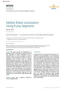
The intrinsic feature of a mobile robot is its ability to move in the surrounding environment. There are many types of robots from the motion point of view, starting from wheeled and ending with legged robots. Although the control of a two wheeled differential drive robot is relatively easy and precise, the more wheels and the more legs the robot has, the more complicated the task is. Humanoid robots, as the representatives of the legged ones, are known to be difficult to precisely navigate, since motion odometry is computed from the relative motion of legs, which often slip, and thus the odometry error is large and increases rapidly. Nao humanoid robot, see Figure 1(a), is equipped with a bunch of various sensors. There are ultrasound sonars, microphones, IR transceivers, an inertial sensor, tactile and pressure sensors, and lastly two cameras. The head of the robot contains also a dual-core ATOM 1.6 GHz CPU, running Linux and firmware controlling the robot. Another CPU is also located in the robot torso. There is a lot of functionality already shipped within the firmware, such as face detection, Naomark detection, see Figure 1(b), walk and some other simple behaviours. C.-Y. Su, S. Rakheja, H. Liu (Eds.): ICIRA 2012, Part II, LNAI 7507, pp. 427–438, 2012. c Springer-Verlag Berlin Heidelberg 2012 �
428
ˇ Fojt˚ S. u, M. Havlena, and T. Pajdla
(a)
(b)
Fig. 1. (a) Nao robot. (b) Example of a Naomark. (courtesy of Ald. Robotics [1]).
The robot has a voice synthesizer and a simple speech recognition module. From our point of view, the most interesting sensors are the two cameras. Since the fields of view of the cameras do not overlap, they cannot be used as a stereo pair and thus we use only one of them. The top camera has 1.22 MPix with 61◦ HFOV and provides VGA resolution in rates slightly over 15 fps (on a Gigabit Ethernet connection). Higher resolution is available with reduced frame rate. Naoqi, the firmware inside the robot, serves as an easy to use robotic framework that allows user modules to communicate with each other and also with various inbuilt modules. The modules can run directly on the robot or as remote applications from a PC. Although Naoqi is a useful framework, there might be needs for a more complex middleware that completely shields the Nao-specific interface from generic applications, such as Robot Operating System (ROS) [14] and Robotics Service Bus (RSB) [18]. We have decided for the latter one that, although being younger, presents an event-driven and message-oriented environment, interfaces with MATLAB and is ported to Nao. We have exploited the modular nature of the middleware to compose our navigation and localization system of separate modules, that can be extended or replaced as needed. The use of this middleware allows others to seamlessly build on our work. In order to navigate a mobile robot, its pose w.r.t. some coordinate system needs to be known. One possible approach is to use artificial markers with known positions in the environment and localize the robot using e.g. a 3-point algorithm [7]. As mentioned above, the robot is equipped with an algorithm to automatically detect Naomarks, so these can be easily used as the artificial markers. This is a valid approach in many fields, e.g. industry [8], where the environment can be created with the robotic needs in mind. In a generic environment, on the other hand, the need for artificial markers of known poses limits the autonomy of the mobile robot and distracts people interacting with the robot. An alternative approach that does not require artificial interventions to the scene is known as Simultaneous Localization and Mapping (SLAM). SLAM
Nao Robot Localization and Navigation Using Fusion
429
combines mapping of surroundings and robot localization, by which it overcomes the classical chicken and egg problem. Impressive example of single camera SLAM is presented by Davison et al. [4]. An example of Nao robot navigation without artificial landmarks is given in the work of Osswald et al. [13]. They improve robot odometry by detecting visual features on a wooden floor. The disadvantage of their approach is the focus on the floor which means that the surroundings are not perceived well.
2
Structure from Motion for Visual Odometry
Structure from motion (SfM) can be used to substitute the artificial markers for the natural ones, i.e. the SURF [2] features automatically detected in the images of the scene. In order to achieve efficient and accurate localization, we decided to split the computation to mapping and visual localization. The task of mapping is to build a 3D model of the environment by the means of SfM methods, whereas the task of visual localization is to quickly estimate robot pose w.r.t. the precomputed 3D model without updating it. 2.1
3D Model Construction
First, the lens distortion model along with internal camera calibration, which facilitates the transformation from image pixel coordinates to unit direction vectors, has to be obtained. Five images of a known calibration grid were used to compute calibration matrix and two parameters of radial distortion according to the polynomial model of degree two for the camera [10]. For constructing the model we have used Bundler [15], which accepts a bunch of images and computes a sparse 3D point cloud model with camera poses. Bundler detects and describes SURF [2] features on all input images and performs exhaustive pairwise feature matching. Promising image pairs are verified w.r.t. epipolar geometry and the “best” image pair is chosen as the seed of the reconstruction. Then, further cameras are added to the model, new 3D points are triangulated [7], and the whole model is refined by sparse bundle adjustment [9] in a loop until there are no feasible cameras left. To improve the quality of the model, internal camera calibration can be fixed during the computation. The sparse 3D point model, as received from Bundler, is transformed according to the user defined real world coordinate system and thus the localization with respect to this model can be considered global. The world coordinate system is defined by assigning desired world coordinates to at least three 3D points manually selected from the model and transforming all the model 3D points to the new coordinates using the computed similarity transform [17]. 2.2
Visual Localization
Visual localization makes use of the sparse 3D point cloud model created during the mapping phase. The visual localization estimating robot camera pose is
430
ˇ Fojt˚ S. u, M. Havlena, and T. Pajdla
(a)
(b)
Fig. 2. Experimental workspace environment with drawings on the walls. (a) Overview of the environment. (b) 3D model resulting from Bundler. 502 estimated camera poses are denoted by red pyramids and 54,450 triangulated 3D points are drawn in real color.
performed in several steps. First, fast SURF [2] features are detected and described in an acquired image. Second, radial undistortion of the detected feature positions is achieved by computing the inverse of the radial distortion function. Next, tentative feature matches w.r.t. the pre-computed 3D model loaded from a file are obtained using FLANN [11] approximate nearest neighbour search in the descriptor space. Finally, the camera pose is estimated from the 3D model by solving the 3-point camera pose problem for a calibrated camera [12] inside of a RANSAC [5] loop. Reprojection error [7] is used as the criterion for tentative match classification to inliers and outliers. Estimated camera pose is considered valid when the number of inliers exceeds a predefined threshold. In some situations, visual localization does not output a valid result. This is caused by e.g. blurred images leading to an insufficient number of image-to3D model point matches. This situation is dealt with during the fusion of data from visual localization and robot odometry.
3
Robot Pose Estimation and Navigation
Next, we investigate how to improve robot pose estimation by fusing visual localization results with robot odometry. 3.1
Robot Odometry
The odometry provided by robot firmware is computed from robot model, i.e. step length and walk angle only, no data from the inertial unit are used (although it is available on the robot). Robot poses output from odometry are relative to some starting point and so only the relative transformations to the previous poses are used in our localization system. The produced poses are known to be biased with an additive error, which is not negligible for legged robots. It was noted in the preliminary experiments that the odometry alone cannot be used
Nao Robot Localization and Navigation Using Fusion
431
Fig. 3. Walk model error in two separate trials. Crosses denote the desired path and circles show the actual traversed path.
for reliable robot navigation, as the resulting robot pose deviates greatly from the ground truth, see Figure 3. Thus another source of robot pose is needed. We have decided to use the information from the robot camera. 3.2
Visual Odometry
The camera pose obtained by visual localization has 6 DOF (3DOF for position and 3DOF for rotation). The robot, on the other hand, has only 3DOF, i.e. it moves in a plane and rotates. The transformation from the general 6D space to 3D is as follows. Let the ground plane be the xy plane. The z axis points upwards and all the axes together form a right-handed coordinate system. Then the 6D to 3D transformation is the vertical projection along the negative z axis, see Figure 4. After this transformation is carried out, the transformation from camera to robot torso must be computed. Since other modules controlling the robot are free to move its head, the transformation from the camera to robot body needs to be known. Currently, only the head yaw angle is used for the camera–body transformation because the distance from the camera center to torso center after projecting to the xy plane is in the order of centimeters and can be neglected. With the knowledge of the overall transformation from 6D camera pose to 3D torso pose, we can now merge the two odometry sources in order to obtain more precise robot pose estimates. 3.3
Fusion of Robot and Visual Odometry
A weighted mean is used to fuse the two sources of pose estimates. During localization, two situations can occur. Either both measurements are available
432
ˇ Fojt˚ S. u, M. Havlena, and T. Pajdla
or only robot odometry is available. The later situation can happen when the received image captures an insufficient part of the modelled scene or is blurred due to robot motion. The treatment of the fusion is thus decomposed into two parts. Let pv , po , and pe be the poses received from visual and robot odometry and the resulting pose estimate, respectively. Since time is discrete, the pose obtained from visual localization in time k can be denoted as pv (k). Let W be a weighting factor that favors visual localization. Thus if W = 1, only data from the camera are considered for pose estimation. Similarly, if W = 0, only robot odometry is used. The pose estimation is then computed as follows pe (k) = W · pv (k) + (1 − W )(pe (k − 1) + po (k)),
(1)
where W = 0.7 if visual localization is known and W = 0 otherwise. This ensures that pose estimation relies more on visual localization, if it is known. In order to internally emphasize the need for visual localization, pose estimate confidence c is introduced. Let confidence c be the probability of the pose being confident, i.e. c = 1 if the robot is confident about the pose and c = 0 if it is completely unsure. From the comparison of the two sources of pose estimates, we would like to increase the confidence if both visual and robot odometry are known and decrease the confidence otherwise. For this purpose a Bayes filter, known from the occupancy grids in robotic mapping, is employed. The pose estimate confidence is computed according to the following update rule c(k + 1) =
p · c(k) , p · c(k) + (1 − p)(1 − c(k))
(2)
where p is a parameter, which is set to 0.8 when both visual and robot odometry are known and to 0.2 if only robot odometry is available. Moreover, the confidence is limited by upper and lower bound, in order to speed up the change of confidence. The proposed update rule has the desired effect of increasing and decreasing the confidence according to the availability of visual localization. 3.4
Navigation
The purpose of navigation is to control the movement of a robot from one pose to another. After all, the term cybernetics stems from the Greek kybern¯et¯es, i.e. steersman. Navigation combines trajectory planning with the execution of the plan, by monitoring the performed actions and adjusting control appropriately. The robot coordinate system is defined as shown in Figure 4. Its origin is in the body center, x axis points ahead of the robot, and y axis points to its left. Let us now focus on processing the fused pose estimates. In some situations, the confidence of robot pose estimate can drop below a predefined threshold cθ , as described in Section 2.2. Navigation reacts to this event in the following way. First, it stops the movement of the robot in order to improve image quality. If this does not improve pose confidence, navigation starts turning robot’s head in order to capture an image with a higher number of matches with the 3D model. Since the maximum yaw of the head is approximately 120◦, it is not needed to
Nao Robot Localization and Navigation Using Fusion
433
y' x'
y
φ
y0
0'
0
x0 x
Fig. 4. Robot pose in world coordinates
turn the whole body. Moreover, with low confidence of the pose, it is not safe to move the whole robot since the robot can be close to an edge of the table or to an obstacle. Once the confidence increases above the threshold cθ , the robot resumes its movement towards the target pose. Although the working space of the robot is bounded by a polygon, it does not need to be convex and thus a more complex method than following a straight line is needed for safely navigating the robot on the table, e.g. for an L-shaped table a simple strategy with a middle point on the table, towards which the robot is walking unless the target pose is reachable along a straight line, can by chosen. 3.5
Simultaneous Localization and Mapping
If localization efficiency and accuracy was not the main concern, one could use also the method presented in [6], which makes use of the sequential Structure from Motion pipeline [16] implemented in MATLAB to construct a 3D model of the environment by the means of SLAM. The robot walks in a stop-and-go fashion capturing images and performing incremental 3D model construction. The direction of walk is continuously being refined by using robot odometry data and, once a partial 3D model is ready, also by visual localization. When needed, loop closing can be used to improve model consistency.
4
Implementation
This section covers the implementation details of the proposed method. Each module, implemented in C++ language, is running separately and can be easily replaced thanks to the employed RSB framework. 4.1
RSB
The RSB framework is basically a bus architecture, connecting various heterogeneous components via a hierarchical broadcast communication, separated into
434
ˇ Fojt˚ S. u, M. Havlena, and T. Pajdla
Fig. 5. Diagram of communication between individual modules and Nao
logical levels, rather than a huge number of peer-to-peer connections. Each module can act as a service provider or consumer and since all are connected via RSB, adding, replacing, or removing modules is seamless and does not interfere with the functionality of other modules [18]. Both visual localization and navigation modules are connected via RSB and communicate with other modules providing sensoric information and performing robot motion, see Figure 5. 4.2
Sensors, Actuators
The images taken by robot camera, joint angles, and robot odometry are all streamed in separate channels (scopes) using the modules distributed with RSB. The navigation module, which also performs odometry fusion should subscribe to all of these in order to receive all the necessary information for successful localization. Since the streams are asynchronous, we have employed an RSB TimeSync module. This module subscribes to several scopes and produces synchronized events via another scope. The navigation module thus subscribes to a single scope and receives all the input information, synchronized in such a way, that the time difference between the events in the original scopes is minimized. The control of Nao is accomplished via an RSB Python RPC Adapter, which allows sending commands directly to NaoSDK without the need of having NaoSDK installed locally. The RPC adapter is employed for walking and turning of head. 4.3
Interface
Protobuf (Google data interchange format) is used for encoding data sent via RSB. Each datum type has its own protocol and the de-/serialization is perfomed
Nao Robot Localization and Navigation Using Fusion
435
by Protobuf. There are many protocol specifications common in robotics defined in Robotics Systems Types (RST) [3]. The visual localization module receives images from robot camera and outputs valid or invalid camera poses which are later synchronized with the output of other robot sensors. The world 3D point cloud and internal camera calibration (with optional radial distortion parameters) are read from a text file. There are several additional optional parameters (blob response threshold of SURF detector, maximum reprojection error for P3P in pixels, RANSAC confidence and maximum number of samples, and number of inliers required for a valid pose estimate), which can be set in order to balance the trade-off between efficiency, precision, and robustness. The input to the navigation module consists of the synchronized sensory output, the description of the working polygon, and target poses. The working polygon is in the form of a sequence of points, denoting vertices, in such a way that consecutive vertices are connected with an edge stored in a text file. The interface for receiving target poses (controlling the robot) is based on a XTTserver architecture, so there is a blocking call to the navigation module, which gains control over the robot motion. Only one call can control the robot at a given time, which is desired. The return value of the call informs whether the target pose was reached or whether it was outside the working polygon of the robot. The two optional parameters are the maximum step size, i.e. the maximal distance between successive poses, and the precision of reaching the goal pose.
5
Experiments
Next, the proposed approach is validated by both the synthetic and real data experiments. 5.1
Synthetic Data
The synthetic experiment is aimed at the fusion of visual and robot odometry data using weighted mean and Bayes filter. The parameters are as follows: weight W = 0.7, Cv = 0.8, and Co = 0.2, lower and upper bounds of pose confidence are set to 0.1 and 0.9, respectively. Robot odometry is modelled as a Gaussian variable with the mean equal to the true relative motion between single steps, the variance in position is equal to 0.02, and the variance in azimuth is equal to 0.03. Visual localization is modelled with the mean corresponding to ground truth and with the same variance as in the odometry model. Ground truth is chosen as 11 points along a straight line 0.1 m apart and the robot is starting at position (0, 0), heading in the direction of the x axis. Three visual localizations are omitted in order to simulate unsuccessful visual localization and demonstrate the change in pose estimate confidence. The confidence decreases, when visual localization is not available (at steps 4, 6, and 7) and increases, as soon as the information is available again, see Figure 6.
436
ˇ Fojt˚ S. u, M. Havlena, and T. Pajdla robot poses 0.3 ground truth visual odometry robot odometry fused odometry
0.2
y [m]
0.1
0
−0.1
−0.2 0
0.2
0.4
0.6 x [m]
0.8
1
confidence
1 0.8 0.6 0.4 0.2
1
2
3
4
5
6
7
8
9
10
11
step
Fig. 6. Robot pose estimate and pose confidence. In positions 4, 6, and 7 the visual localization is missing—note the decrease in pose confidence.
5.2
Real Data
We used a simple RSB module to store all the images acquired by the top camera in PGM files and guided the robot manually through the scene in an approximately two minutes long sequence. Next, every fifth image of the sequence was selected giving raise to 504 VGA images of the scene. These were radially undistorted and passed to Bundler set in a way to use SURF features with threshold value 15 and known fixed internal camera calibration. The resulting 3D model obtained after 6.5 hours of computation consisted of 502 camera poses and 54,450 3D points, see Figure 2(b). As a model with a relatively small number of high-quality 3D points is more suitable for subsequent localization than a model with a large number of mediumquality 3D points, we performed additional 3D point selection based on the number of verified 3D point projections to the images. Only 5,045 3D points having more than 15 verified projections were selected and exported to the resulting model file together with the SURF descriptors transferred from the images. The actual experiment is performed on the real robot in order to demonstrate the ability to localize robot body w.r.t. the precomputed 3D model. The robot is placed in our workspace, shown in Figure 2(a), and moved manually along an L-shaped path, while the visual localization is running. The path is straight except for the beginning and the corner, where the robot turns 90◦ to the right. In Figure 7(a), the path starts at the lower part, with the robot facing down. Although the robot was moved by hand, the real trajectory deviates from a straight
Nao Robot Localization and Navigation Using Fusion
(a)
437
(b)
Fig. 7. Results of Nao localization w.r.t. the precomputed 3D model along an L-shaped path. Estimated camera locations for the head are denoted by red dots, the 5,045 3D points of the model are drawn in real color. (a) Top view. (b) Side view.
line at most by 1 cm. There is no ground truth available for this experiment but the reconstructed path is close to the true one, except for two obvious invalid localizations, which would be filtered out. The data shown in Figure 7 are directly from the visual localization, which works independently on each received image and uses no information about the desired trajectory or any motion model. The process of visual localization is running at approximately 8 fps on a 64bit i5 laptop. The error of determining robot pose from visual odometry has a normal distribution around the true pose and thus nicely complements the additive error of pose estimation from robot odometry.
6
Conclusion
We have shown the possibility of enabling visual odometry of humanoid robot Nao using Structure from Motion without the need for artificial markers in the scene. Our approach improves robot pose estimation using fusion of odometry provided by robot firmware and visual localization by employing weighted mean and Bayes filter for updating pose confidence. The proposed modular implementation does not depend on any specific robot type thanks to the RSB middleware that connects all the components. The performance of our algorithm is demonstrated on synthetic and real experiments, showing the precision of visual localization and the improvement brought about by data fusion. Acknowledgements. This work was supported by projects SGS12/187/OHK3/3T/13, SGS12/191/OHK3/3T/13, and FP7-ICT-247525 HUMAVIPS.
438
ˇ Fojt˚ S. u, M. Havlena, and T. Pajdla
References 1. Aldebaran Robotics: Nao Hardware Specification for SDK v1.12 (2012), http://www.aldebaran-robotics.com/documentation/nao/hardware/index.html 2. Bay, H., Ess, A., Tuytelaars, T., Van Gool, L.: Speeded-up robust features (SURF). CVIU 110(3), 346–359 (2008) 3. Bielefeld University: Robotics Service Types (2012), https://code.cor-lab.org/projects/rst 4. Davison, A.J., Reid, I.D., Molton, N.D., Stasse, O.: MonoSLAM: real-time single camera SLAM. IEEE Transactions on Pattern Analysis and Machine Intelligence 29(6), 1052–1067 (2007) 5. Fischler, M., Bolles, R.: Random sample consensus: A paradigm for model fitting with applications to image analysis and automated cartography. Comm. ACM 24(6), 381–395 (1981) ˇ Nao Localization and Navigation Based on Sparse 3D Point Cloud Re6. Fojt˚ u, S.: construction. Master’s thesis, Czech Technical University in Prague (2011) 7. Hartley, R., Zisserman, A.: Multiple View Geometry in Computer Vision, 2nd edn. Cambridge University Press (2003) 8. Hu, H., Gu, D.: Landmark-based Navigation of Industrial Mobile Robots. Industrial Robot: An International Journal 27(6), 458–467 (2000) 9. Lourakis, M.I.A., Argyros, A.A.: SBA: A software package for generic sparse bundle adjustment. ACM Transactions on Mathematical Software (2009) 10. Mareˇcek, P.: A Camera Calibration System. Master’s thesis, Center for Machine Perception, K13133 FEE Czech Technical University, Czech Republic (2001) 11. Muja, M., Lowe, D.: Fast approximate nearest neighbors with automatic algorithm configuration. In: VISAPP 2009 (2009) 12. Nist´er, D.: A minimal solution to the generalized 3-point pose problem. In: CVPR 2004. pp. I:560–I:567 (2004) 13. Osswald, S., Hornung, A., Bennewitz, M.: Learning reliable and efficient navigation with a humanoid. In: 2010 IEEE International Conference on Robotics and Automation (ICRA), pp. 2375–2380. IEEE (2010) 14. Quigley, M., Conley, K., Gerkey, B.: ROS: an open-source Robot Operating System. In: Open-Source Software workshop of the International Conference on Robotics and Automation, ICRA 2009 (2009) 15. Snavely, N., Seitz, S., Szeliski, R.: Modeling the world from internet photo collections. IJCV 80(2), 189–210 (2008) 16. Torii, A., Havlena, M., Pajdla, T.: Omnidirectional image stabilization for visual object recognition. International Journal of Computer Vision 91(2), 157–174 (2011) 17. Umeyama, S.: Least-squares Estimation of Transformation Parameters Between Two Point Patterns. IEEE Transactions on Pattern Analysis and Machine Intelligence, 376–380 (1991) 18. Wienke, J., Wrede, S.: A Middleware for Collaborative Research in Experimental Robotics. In: 2011 IEEE/SICE International Symposium on System Integration, SII 2011, Kyoto, Japan, pp. 1183–1190 (2011)