Feb 29, 2012 - [3] Aldebaran Robotics â Nao Hardware Specification for SDK v1.12. http://www.aldebaran-robotics.com/documentation/nao/.
CENTER FOR MACHINE PERCEPTION
Nao Robot Localization and Navigation with Atom Head CZECH TECHNICAL UNIVERSITY IN PRAGUE
ˇ Michal Havlena, Simon Fojt˚ u, Tom´aˇs Pajdla {havlem1, fojtusim, pajdla}@cmp.felk.cvut.cz
CTU–CMP–2012–07
Available at ftp://cmp.felk.cvut.cz/pub/cmp/articles/havlena/Havlena-TR-2012-07.pdf The work was supported by the EC project FP7-ICT-247525 HUMAVIPS. Any opinions expressed in this paper do not necessarily reflect the views of the European Community. The Community is not liable for any use that may be made of the information contained herein. Research Reports of CMP, Czech Technical University in Prague, No. 7, 2012 ISSN 1213-2365
RESEARCH REPORT
February 29, 2012
Published by Center for Machine Perception, Department of Cybernetics Faculty of Electrical Engineering, Czech Technical University Technick´a 2, 166 27 Prague 6, Czech Republic fax +420 2 2435 7385, phone +420 2 2435 7637, www: http://cmp.felk.cvut.cz
Nao Robot Localization and Navigation with Atom Head ˇ Michal Havlena, Simon Fojt˚ u, Tom´aˇs Pajdla February 29, 2012
Abstract Robot localization and navigation from vision both make use of Structure from Motion (SfM). First, it is shown that image quality, a crucial assumption for successful SfM, of the two cameras in the v4.0 Nao Atom head has been improved when compared to the original Nao Geode head. Secondly, the implementation of different SfM functionalities into individual modules connected through the RSB architecture is described. In our specification, the mapping module creates a 3D model, the localization module estimates camera pose w.r.t the model, and the navigation module plans robot trajectories and performs the actual movement.
1
Introduction
Recently, a new v4.0 head for Nao robot [3] appeared, bringing not only significant increase in performance by using the dual-core Atom processor but also improved quality of the sensors. In this report, we present our experiments with the new head, namely the two cameras, relevant to the goals of HUMAVIPS project which is solving the ultimate goal of robot-tohuman interaction. Our task in the project is to provide: (i) camera calibration, (ii) mapping of the environment, (iii) localization of the robot in the mapped environment, and (iv) navigation in the environment using the results of localization. This all is implemented in the common RSB architecture [11] which allows other modules to subscribe to the results of our components when solving higherlevel tasks. 1
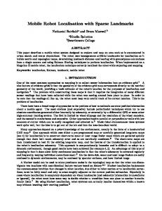
Figure 1: Nao Atom head, HUMAVIPS edition, with two 1.22Mpix cameras placed in Nao’s eyes forming a synchronized stereo-pair able to provide VGA images at 15 fps.
2
Atom Head Hardware
The new head supplied by the project partner, Aldebaran Robotics, has the following specifications: • Processor: ATOM Z530, 1.6Ghz, dual-core • Memory: 1GB RAM, 2GB Flash Memory • Network: Gigabit Ethernet, 802.11b/g • Sound: 2 lateral loudspeakers having 2W • Microphones: 4 microphones with SNR 58dBA • Cameras: 2 cameras having 1.22MPix with 61◦ HFOV The Atom head for HUMAVIPS project, see Figure 1, differs from the standard Atom v4.0 Nao head by the position of the cameras, which are not placed in the forehead and mouth but in the eyes instead. This allows 2
(a)
(b)
(c)
(d)
Figure 2: Comparison of the images from the cameras of the old and the new Nao head. Note the improved sensitivity of the sensor and field of view of the lens (the position of the robot was approximately the same when acquiring the images). (a) Geode head, bright scene. (b) Geode head, dark scene. (c) Atom head, bright scene. (d) Atom head, dark scene. for stereoscopic image processing as image overlap of left and right camera view fields is nearly total. The field of view of the lens and the sensitivity and the resolution of the cameras have also been significantly improved when compared to the cameras in the original Geode head removing most of the difficulties we were experiencing with the old head [5], see Figure 2. Furthermore, the upgrade of the wired network interface to gigabit Ethernet (1000BASE-T) allows for sending synchronized pairs of images in VGA resolution via RSB in rates slightly over 15 fps. For our applications of environment mapping and robot localization, only the left camera is used and frame rate is not so crucial, but the components of other partners do make great benefit of this. 3
(a)
(b)
Figure 3: Two of the five images of a known calibration grid which were used to calibrate Nao’s left camera. Pixel correspondence can be easily obtained due to the specific layout of white and black dots.
3
Camera Calibration
Internal camera calibration, which facilitates the transformation from image pixel coordinates to unit direction vectors, was obtained off-line [6]. Five images of a known calibration grid, see Figure 3, were used to compute calibration matrix and two parameters of radial distortion according to the polynomial model of degree two for both Nao’s cameras independently. left camera: K =
551.9883 0 0
0 554.5573 0
308.1227 255.3918 1.0000
0 553.2588 0
325.9151 226.1525 1.0000
right camera: K =
550.6527 0 0
Images are radially undistorted before being used for further computation in order to improve the results of SfM. This is achieved by computing the inverse of the radial distortion function and by performing the actual undistortion using bicubic image interpolation. 4
4
Mapping and Localization
Mapping and localization are the two desired functionalities which make use of Structure from Motion (SfM). Due to the large diversity of requirements placed on the two functionalities, we decided to split the SfM module into two: (i) mapping module building the 3D model of the static environment by the means of SLAM or other methods and (ii) localization module able to quickly estimate robot pose w.r.t the precomputed 3D model without updating it.
4.1
3D model construction
The method presented in [5], which makes use of the sequential Structure from Motion pipeline [10], was further extended in order to perform an autonomous robot walk following a prescribed trajectory. The robot walks in a stop-and-go fashion capturing images and performing incremental 3D model construction. The direction of walk is continuously being refined by using robot odometry data and, once a partial 3D model is ready, also by visual odometry. When needed, loop closing can be used to improve model consistency. Due to the dependence on [10], the mapping module is implemented in MATLAB and connected with RSB via RSBJava. It subscribes the image and odometry channels to receive recent sensor data and operates the robot via RSB Python RPCAdapter which allows sending NaoSDK commands to the robot without the need of having NaoSDK installed locally. In order to be able to use the constructed model in subsequent localization which is based on fast SURF [1] features, one has to restrict image features used to SURF only. This together with the fact that the proposed robot environment for the “Gallery” scenario, the L-shaped table with drawings on the walls, see Figure 4(a), is quite challenging for SLAM due to very limited operating space of the robot currently causes problems to the SLAM-based mapping. Therefore, we decided to use an alternative mapping method based on Bundler [9]. We used rsbimagesaver to store all the images acquired by the left camera to PGM files and flew the robot manually through the scene in an approximately two minutes long sequence. Next, every fifth image of the sequence was selected giving raise to 504 VGA images of the scene. These were radially undistorted and passed to Bundler set in a way to use SURF features with threshold value 15 and known fixed internal camera calibration. The resulting 3D model obtained after 6.5 hours of computation consisted of 502 camera poses and 54,450 3D points, see Figure 4(b). 5
(a)
(b)
Figure 4: The L-shaped table with drawings on the wall, the proposed robot environment for the “Gallery” scenario. (a) Overview of the environment. (b) 3D model resulting from Bundler. 502 estimated camera poses are denoted by red pyramids and 54,450 triangulated 3D points are drawn in real color. As a model with a relatively small number of high-quality 3D points is more suitable for subsequent localization than a model with a large number of medium-quality 3D points, we performed additional 3D point selection based on the number of verified 3D point projections to the images. Only 5,045 3D points having more than 15 verified projections were selected and exported to the resulting model file together with the SURF descriptors transferred from the images.
4.2
Localization w.r.t the precomputed 3D model
The localization module making use of the RSB architecture has been implemented in C++ in order to gain maximum performance possible. The module subscribes the image channel to receive recent frames and sends either the computed camera pose or an empty pose in situations, when camera pose could not be reliably computed, via RSB so that other modules can subscribe to the respective channel and receive the results. On the algorithmic side, the method for camera pose estimation has been largely simplified. First, SURF [1] image features are computed on incoming image data without performing radial undistortion. Next, tentative feature matches w.r.t the pre-computed 3D model loaded from a file are obtained using FLANN [7] approximate nearest neighbour search in the descriptor space. This search is performed one-way only, i.e. the descriptors detected in the incoming image are matched using a static database index computed just once from the loaded 3D model when the module starts, bringing another 6
speedup. The pose of the camera is obtained by solving the 3-point camera pose problem for calibrated generalized camera [8] in a RANSAC [2] loop. Reprojection error [4] is used as the criterion for tentative match classification to inliers and outliers. Due to performance issues, no model refinement from all the inliers is performed. Estimated camera pose is passed to the output when the number of inliers exceeds a predefined threshold. The parameters of the module, configurable through the command-line interface, are the following: • 3D model file – file with model 3D points, see below • Calibration file – file with internal camera calibration as a 3x3 K matrix • Input image RSB scope – default ”/nao/vision/top” • Output pose RSB scope – default ”/nao/camerapose/top” • Blob response threshold for SURF detector – default 4 • Number of FLANN checks during matching – default 256 • Second closest nearest neighbour ratio for FLANN – default 0.75 • Minimum number of inlier points – default 10 • Maximum reprojection error [px] – default 0.5 • RANSAC confidence – default 0.9999 • Maximum number of RANSAC samples – default 1000 The format of the 3D model file which is precomputed in the mapping phase and exported: 65 n X1 Y1 Z1 R1 G1 B1 desc1_1 desc1_2 ... desc1_64 X2 Y2 Z2 R2 G2 B2 desc2_1 desc2_2 ... desc2_64 ... Xn Yn Zn Rn Gn Bn descn_1 descn_2 ... descn_64 where X, Y, Z are the 3D point coordinates in the world coordinate system, R, G, B is the color of the point and desc 1 ... desc 64 are the 64 values of the SURF descriptor of the point transferred from the image. In our experiment, we compare the localization performance of the old Geode and the new Atom head. We ran the localization module with SURF 7
(a)
(b)
Figure 5: Results of Nao localization w.r.t the precomputed 3D model. Estimated camera locations for the Geode and the Atom head are denoted by green and red dots respectively, the 5,045 3D points of the model are drawn in real color. (a) Top view. (b) Side view. feature threshold set to 15 to be the same as used during mapping and maximum reprojection error 1.5 pixel to allow for inaccuracies caused by ignoring radial distortion. Then, we moved the robot manually on the table along a straight trajectory with turns while facing the drawings. Camera poses obtained at approximately 2 fps were plotted in a figure containing the model 3D points, see Figure 5. The trajectory obtained when using the new head is more complete and contains less jitter.
5
Navigation of Nao
First, coordinate systems must be set up. The world coordinate system can be defined after the 3D model has been computed by assigning desired world coordinates to at least three 3D points manually selected from the model and transforming all the model 3D points to the new coordinates using the computed similarity transform. Locations of the individual drawings, which may be the navigation targets, are also set manually in the 3D model. Let us define the robot coordinate system, whose origin is in the camera center and whose x axis points ahead of the robot and y points to its left. The situation is shown in Figure 6. Since other modules controlling the robot can move its head, the transformation from the camera to robot body 8
y' x'
y φ
y0
0'
0
x0 x
Figure 6: Robot pose in world coordinates. needs to be known. This information is received via RSB in the form of joint angles. Currently, only the head yaw angle is used for the camera–body transformation. Input to the navigation module consists of the 3D model precomputed in the mapping phase, robot odometry data sent through RSB, results from localization module also obtained via RSB and the desired target pose received from the higher-level modules which may ask the robot to move somewhere as a part of fulfilling a complex task. When a desired target pose is received, the feasibility of reaching the pose is determined. Then, either a path is found and the robot starts walking along it or an error message is sent via RSB. In some situations, the localization module does not output any results. This can be caused by e.g. blurred images or an insufficient number of imageto-3D model point matches. The navigation module reacts in two ways. First, it tries to improve image quality by interrupting robot movement. If the localization results is still unsatisfactory, Nao starts turning around in order to capture images of other parts of the scene which may have higher number of matches with the 3D model than the original one. After the current robot pose is recovered, the walk is resumed. An information message is sent over RSB when the target pose is reached. 9
6
Conclusion
We have shown that the cameras of the new v4.0 Nao Atom head provide much better images than the cameras of the old Nao Geode head which improves SfM computation results. The proposed decomposition of the desired SfM-based functionalities to mapping, localization, and navigation modules leads to fast robot pose estimation during localization as the time-consuming model construction is performed just once during mapping and to navigation based on more inputs than just results of SfM. This decomposition is possible thanks to the underlying RSB architecture which allows message interchange between the modules and supplies them with recent image data from the robot.
References [1] H. Bay, A. Ess, T. Tuytelaars, and L.J. Van Gool. Speeded-up robust features (SURF). CVIU, 110(3):346–359, June 2008. [2] M. Fischler and R. Bolles. Random sample consensus: A paradigm for model fitting with applications to image analysis and automated cartography. Comm. ACM, 24(6):381–395, June 1981. [3] Aldebaran Robotics – Nao Hardware Specification for SDK v1.12. http://www.aldebaran-robotics.com/documentation/nao/ hardware/index.html, 2012. [4] R.I. Hartley and A. Zisserman. Multiple View Geometry in Computer Vision. Cambridge University Press, second edition, 2003. ˇ Fojt˚ [5] M. Havlena, S. u, D. Pr˚ uˇsa, and T. Pajdla. Towards robot localization and obstacle avoidance from nao camera. Research Report CTU– CMP–2010–18, Center for Machine Perception, K13133 FEE Czech Technical University, Prague, Czech Republic, 2010. [6] P. Mareˇcek. A camera calibration system. Master’s thesis, Center for Machine Perception, K13133 FEE Czech Technical University, Prague, Czech Republic, 2001. [7] M. Muja and D. Lowe. Fast approximate nearest neighbors with automatic algorithm configuration. In VISAPP09, 2009. [8] D. Nist´er. A minimal solution to the generalized 3-point pose problem. In CVPR 2004, pages I:560–567, 2004. 10
[9] N. Snavely, S. Seitz, and R. Szeliski. Modeling the world from internet photo collections. IJCV, 80(2):189–210, 2008. [10] A. Torii, M. Havlena, and T. Pajdla. Omnidirectional image stabilization for visual object recognition. International Journal of Computer Vision, 91(2):157–174, January 2011. [11] Bielefeld University – Robotics Service Bus v0.5. cor-lab.org/projects/rsb, 2012.
11
https://code.