energy to the near-inertial subharmonic via parametric subharmonic instability (PSI). The near-inertial ..... while the phase speed of vertical mode one, c1, is between 2 and 4 m sâ1. ..... (a) In the upper panel the growth rate asymptotes to. 1.
1
Under consideration for publication in J. Fluid Mech.
Near-inertial parametric subharmonic instability By W.R. Young1 , Y.K. Tsang
1
and N.J. Balmforth2
1
Scripps Institution of Oceanography, University of California, San Diego, CA 92093-0230, USA. 2 Departments of Mathematics and Earth & Ocean Science, University of British Columbia, Vancouver, Canada. (Received 4 February 2008)
New analytic estimates of the rate at which parametric subharmonic instability (PSI) transfers energy to high vertical wavenumber, near-inertial oscillations are presented. These results are obtained by a heuristic argument which provides insight into the physical mechanism of PSI, and also by a systematic application of the method of multiple time-scales to the Boussinesq equations linearized about a “pump wave” whose frequency is close to twice the inertial frequency. The multiple-scale approach yields an amplitude equation describing how the 2f0 -pump energizes a vertical continuum of near-inertial oscillations. The amplitude equation is solved using two models for the 2f0 -pump: (i) an infinite plane internal wave in a medium with uniform buoyancy frequency (ii) a vertical mode one internal tidal wavetrain in a realistically stratified and bounded ocean. In case (i) analytic expressions for the growth rate of PSI are obtained and validated by a successful comparison with numerical solutions of the full Boussinesq equations. In case (ii), numerical solutions of the amplitude equation indicate that the near-inertial disturbances generated by PSI are concentrated below the base of the mixed layer where the velocity of the pump wave train is largest. Based on these examples we conclude that the e-folding time of PSI in oceanic conditions is on the order of ten days or less.
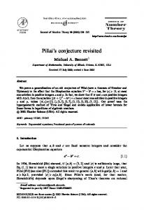
1. Introduction Mixing a stably stratified ocean by breaking internal gravity waves requires the transfer of energy from the low vertical modes excited by wind and tides to near-inertial waves with small vertical scale. Hibiya, Nagasawa & Niwa (2002) and MacKinnon & Winters (2005, 2007) have discovered an important route for this transfer: at the specific latitude 28.8◦ , where the M2 tidal frequency is equal to twice the local inertial frequency, a northward propagating M2 internal tide, with mode one vertical structure, rapidly transfers energy to the near-inertial subharmonic via parametric subharmonic instability (PSI). The near-inertial wave at the critical latitude 28.8◦ N has small vertical scale and large shear so that overturning and mixing is indicated. Earlier work by Nagasawa, Niwa & Hibiya (2000) argues that near-inertial waves generated by mid-latitude storms in the North Pacific propagate equatorward till their frequency is equal to twice the local inertial frequency. At this point PSI rapidly transfers energy to half-frequency near-inertial waves with much smaller vertical scale. Figure 1 illustrates PSI and the excitation of small vertical scales using a numerical solution of the two-dimensional Boussinesq equations. Using a global tidal model, Simmons (2007) shows a web of filamentary M2 internal wave beams radiating from topographic wavemakers. The 21 M2 subharmonic is generated when beams cross the critical latitude, resulting in an accumulation of near-inertial
2
W. R. Young, Y. K. Tsang and N.J. Balmforth
v (ms−1)
8000 0.03
270 days 267 days 252 days
7000 0.02 6000
6000
0.01
z (m)
−0.01
z (m)
5000
0
4000
4000
−0.02 3000 −0.03 −0.04 −0.05 −0.06
2000
2000
1000
0
0
2
4
6 x (m)
8
10
0
12 4
x 10
-0.06
-0.04
-0.02 0.00 -1 v (ms )
0.02
0.04
Figure 1. A solution of the two-dimensional Boussinesq equations obtained using the stream function-vorticity formulation and a pseudospectral code. The initial condition is an infinite plane wave, as in (4.1), plus very small random noise. The wavenumbers are k = 2π/(129×103 m) and m = 2π/(8×103 m), corresponding to the gravest length scales of the computational domain. The wave amplitude is a = 0.1551m2 s−2 so that the wave has a root mean square horizontal velocity of 5.65cm s−1 . The Coriolis frequency f0 = 7.04 × 10⁻⁵ s−1 , corresponds to 28.8◦ North, ω = M2 = 2f0 and N = 28f0 . The left panel shows a snapshot of the meridional velocity v(x, z, t) at t = 270 days. The right panel shows vertical profiles of v; in the profile at t = 252 days the small noise is not yet evident. In the later two profiles, PSI has amplified the noise into a near-inertial oscillation with relatively small vertical scale.
energy and shear at 28.8◦ . In another numerical study, Gerkema, Staquet & BouretAubertot (2006) show that M2 tidal beams generated at the shelf-break are subject to PSI which generates near-inertial disturbances along the beam: PSI is so rapid that there is considerable energy transfer to 21 M2 even before the first bottom bounce. These recent works force a revision of results concerning nonlinear interactions between oceanic internal gravity waves and the role of PSI in moving energy to near-inertial waves of small vertical scale. In particular Olbers & Pomphrey’s (1981) conclusion that the “spreading of tidal energy across the internal wave continuum by resonant coupling · · · is irrelevant for the energy balance” must be reassessed. This is symptomatic of a larger issue: there is uncertainty about nonlinear internal wave interaction rates, and this uncertainty is most acute for interactions involving the near-inertial spectral peak (Garrett & St. Laurent 2002). Most of the early research on interactions among ocean internal gravity waves summarized by M¨ uller et al. (1986) is based on the random phase assumption; this leads to slow interaction rates and inefficient energy transfer. The numerical studies discussed above indicate that the coherent waves generated by tides and large-scale atmospheric forcing have much faster transfer rates. However there are significant differences regarding the growth rate of PSI even amongst these investigators: MacKinnon & Winters (2005, 2007) find that the e-folding time is 5 or 10 days in their simulations; Gerkema et al. (2006) find a 2 day e-folding time; Simmons (2007) estimates an e-folding time of roughly 15 days. The growth rate of PSI depends on the amplitude and structure of the primary M2 tidal wave so these disparities might be
Near-inertial PSI
3
expected in differently configured simulations. One of our goals here is to provide reliable analytic estimates for the rate at which energy is transferred to the near-inertial spectral peak by the parametric subharmonic instability of a coherent wave with frequency close to 2f0 . We emphasize the importance of rotation: much of the previous theoretical and experimental work on PSI has focussed on excitation and breaking in the non-rotating case (e.g., Mied 1976; Drazin 1977; Klostermeyer 1991; Bouruet-Aubertot, Sommeria & Staquet 1995; Benielli & Sommeria 1998). Here we are concerned with a particular type of PSI — near-inertial PSI — in which the primary wave has a frequency ω ≈ 2f0 , where f0 is the local inertial frequency, so that the recipient subharmonic is a near-inertial oscillation. In this rotationally dominated situation, the energy transfer is particularly strong because near-inertial oscillations are almost stationary and therefore might dissipate locally forming MacKinnon & Winters’s “subtropical catastrophe”. In section 2 we show that for near-inertial PSI there is a simple fluid-mechanical solution which is more informative than the pendulum analogy. In section 3 we extend and develop the formalism of Young & Ben Jelloul (1997) to obtain a general description of the excitation of near-inertial waves by PSI. In section 4 we use the amplitude equation from section 3 to analyze the stability of an infinite plane internal gravity wave. This analysis provides analytic expressions for the growth rate of PSI. The reduced description of section 3 is validated by a successful comparison of the analytic growth rate with numerical solutions of the Boussinesq equations. In section 5 we consider the parametric instability of a vertical mode one, tidal wavetrain in a realistically stratified ocean. In section 6 we discuss the main results of this article, emphasizing that PSI does not select a preferred vertical scale.
2. The physical basis of near-inertial PSI PSI is one of the three classes of resonant interactions identified by McComas & Bretherton (1977) as dominating energy transfer rates between internal gravity waves under rapidly rotating conditions in the ocean. In the original conception of McComas & Bretherton, PSI transfers energy from low wavenumbers with frequency ω to high wavenumbers with frequency ω/2. Transfer to the subharmonic ω/2 is reminiscent of the response of a pendulum with a vertically oscillated support, and this mechanical analogy is often the basis of a physical explanation of PSI (e.g., as in Benielli & Sommeria 1998). However in the special case of PSI with ω ≈ 2f0 there is an alternative and more informative fluid mechanical explanation. Thus as a motivating preamble to the more general discussion in section 3, we first consider an idealized limit in which (U, V ) denotes the horizontal velocity of the background flow where, following Weller (1982), �� � � � � x U Ux Uy . (2.1) = y Vx Vy V The entries of the 2 × 2 matrix above are functions of depth z and time t and incompressibility demands that the vertical velocity W (z, t) is given by Ux + Vy + Wz = 0. Now we consider how the background flow (U, V, W ) interacts with a pure inertial oscillation. By a pure inertial oscillation we mean a disturbance with infinite spatial scale in the horizontal so that the velocity is [u(z, t), v(z, t), 0]. A pure inertial oscillation has no pressure or buoyancy signal and thus the dynamics are entirely governed by the
4
W. R. Young, Y. K. Tsang and N.J. Balmforth
horizontal momentum equations: ut + W uz + uUx + vUy − f0 v = 0 , vt + W vz + uVx + vVy + f0 u = 0 .
(2.2)
The energy equation obtained from (2.2) is et + W ez − Wz e + 21 (u2 − v 2 )(Ux − Vy ) + uv(Uy + Vx ) = 0 ,
(2.3)
where e ≡ 21 (u2 + v 2 ) is the energy density of the inertial oscillation. For a pure inertial oscillation, the quantities u2 − v 2 and uv prominently contain the second harmonics exp(±2if0 t), while e = 21 (u2 + v 2 ) contains only the zero frequency. Thus, from (2.3), one can anticipate the existence of parametric subharmonic instability provided that the background strain rates Ux − Vy and Uy + Vx also contain the 2f0 harmonic. Then the combinations 21 (u2 − v 2 )(Ux − Vy ) and uv(Uy + Vx ) can reinforce the zero-frequency in e. We refer to this as “2f0 -pumping”. Because e contains only the zero frequency, the spectral content of W at 2f0 does not lead to instability via W ez and Wz e in (2.3). Instead, a zero-frequency component in W might result in instability via W ez and Wz e. However we assume that the lowfrequency part of the background flow is in geostrophic balance and consequently there is no zero-frequency spectral content in W . The growth rate of the instability can be calculated with a simple averaging argument as detailed shortly. The main deduction from (2.3) is that energy transfer to the nearinertial peak is associated with the spectral content of the the strain rates Ux −Vy and Uy + Vx at 2f0 . Neither the vertical vorticity nor the horizontal divergence of the background flow are decisive. Vertical straining via Wz is not the essential physical mechanism of near-inertial PSI: the instability is driven by 2f0 -pumping. To quantify this further it is convenient to first rewrite (2.2) exactly in terms of the “back-rotated” velocity Q(t, z) ≡ exp(if0 t) (u + iv) as [(Ux − Vy ) + i(Vx + Uy )] e2if0 t Q∗ = 0 . (2.4) We assume that background flow and the near-inertial oscillation interact weakly so that the envelope Q(z, t) is evolving slowly relative to the inertial time scale. The secular evolution of Q(z, t) is then obtained by time-averaging (denoted by an overbar) (2.4) over an interval which is long relative to f0−1 : Qt + W Qz +
where †
1 2
[(Ux + Vy ) + i(Vx − Uy )] Q +
1 2
¯ t + 1 iζ Q ¯ + 1 ΥQ ¯∗ = 0 , Q 2 2
(2.5)
¯y , ζ ≡ V¯x − U
(2.6)
Υ ≡ [(Ux − Vy ) + i(Vx + Uy )] e2if0 t ,
(2.7)
is the vertical vorticity of the low-frequency part of the background flow. The term involving 12 iζ in (2.5) is Kunze’s (1985) result that the effective inertial frequency is shifted away from the local inertial frequency by half of the relative vorticity of the lowfrequency geostrophic background flow — see also Klein & Llewellyn Smith (2001) and Klein, Llewellyn Smith & Lapeyre (2004). The other coefficient in (2.5) is the amplitude of the 2f0 -pump: which is non-zero if the background strain rates have spectral content at 2f0 . † In passing from (2.4) to (2.5) we assume that the low-frequency part of the background flow ¯ =U ¯x + V¯y = 0. is geostrophically balanced so that W
Near-inertial PSI
5
To illustrate this transfer of energy, suppose that ζ is constant and that the background flow in (2.7) contains the frequencies ±(2f0 + σ), where σ ≪ 2f0 is a small de-tuning of the resonance. In this case Υ = Υ0 exp(−iσt). The solution of (2.5) has the form � � 1 ¯ = e− 2 iσt A1 est + A∗2 es∗ t , (2.8) Q
where
s2 = 14 |Υ0 |2 −
1 4
(ζ − σ)2 .
(2.9)
The strength of the 2f0 -pump exceeds de-tuning if |Υ0 | > |ζ −σ| and then s is real so that the energy of the inertial oscillation grows exponentially via PSI. The expression for the growth rate s in (2.9) points to an interesting competition between Kunze’s frequency shift ζ/2, the de-tuning σ and the pump strength |Υ0 |.
3. A general framework for near-inertial PSI In section 2 we considered an idealized limit in which the background flow has a very large scale as in (2.1), and the near-inertial oscillation has an even larger horizontal scale. We now lift these assumptions regarding the idealized spatial structure of the solution and develop a general framework describing the evolution of near-inertial oscillations. Young & Ben Jelloul (1997) considered the propagation of near-inertial oscillations through a geostrophic flow which changes slowly relative to the inertial period. Our strategy is to extend the multiple time-scale approach of Young & Ben Jelloul by considering a background flow consisting of both a geostrophic component and a 2f0 -pump flow. Young & Ben Jelloul show that there is no transfer of energy between the geostrophic part of the background flow and the near-inertial waves. This result has been confirmed via higher order asymptotics by Reznik et al. (2001). Thus the 2f0 -pump component of the background plays the essential role of energizing the near-inertial oscillations via the mechanism of section 2. We use the β-plane approximation pivoted around f0 : f = f0 + βy .
(3.1)
As in section 2 we use (U, V, W, B, P ) to denote the velocity, buoyancy and pressure of the background flow. With (u, v, w, b, p) we denote the fields associated with the near-inertial oscillation. Thus, for example, the total density field has the form � � Z z N 2 (z ′ ) dz ′ − g −1 B − g −1 b , (3.2) ρ = ρ0 1 − g −1 0
2
where N (z) is the buoyancy frequency and the background buoyancy is B(x, t) = Bg (x, t) + Bp (x, t) .
(3.3)
In (3.3) Bg is the buoyancy of the geostrophic flow and the pump buoyancy Bp is ∗
Bp (x, t) = B˜p (x, t)e2if0 t + B˜p (x, t)e−2if0 t .
(3.4)
The envelope B˜p evolves on the slow time scale i.e., the carrier exp(±2if0 t) in (3.4) contains the dominant frequency 2f0 . There is an analogous decomposition (geostrophic, g, plus pump, p) for the other background fields. The geostrophic component can be derived from a stream function, ψ = Pg /f0 , via (Ug , Vg , Wg , Bg ) = (−ψy , ψx , 0, f0 ψz ) .
(3.5)
6
W. R. Young, Y. K. Tsang and N.J. Balmforth
Thus, for example, the background zonal velocity is ∗ U = −ψy + U˜p e2if0 t + U˜p e−2if0 t .
(3.6)
Because the geostrophic vertical velocity is zero, W (x, t) consists solely of the pump component: ˜p∗ e2if0 t + W˜p e−2if0 t . (3.7) W =W Linearizing the Boussinesq equations around the background we obtain: ut + U ux + V uy + W uz + uUx + vUy + wUz − f v + px = 0 , vt + U vx + V vy + W vz + uVx + vVy + wVz + f u + py = 0 ,
(3.8) (3.9)
−b + pz = 0 , ux + vy + wz = 0 ,
(3.10) (3.11)
bt + U bx + V by + W bz + uBx + vBy + wBz + wN 2 = 0 .
(3.12)
We emphasize that the PSI is driven solely and essentially by the pump component of the background flow e.g., Up in (3.6). The geostrophic component, which is derived from ψ, is included to make contact with the earlier results in Young & Ben Jelloul (1997), and because the interaction of the near-inertial disturbances with geostrophic flow is a crucial oceanic process (Kunze 1985; Klein et al. 2004). 3.1. Scaling assumptions Now we reduce the linear problem in (3.8) through (3.12) using the assumption that (u, v, w, p, b) is a slowly modulated near-inertial disturbance. This requires three assumptions. First, the time dependence of both the geostrophic component, Bg , and the pump modulation, B˜p , is slow relative to the inertial time-scale f0−1 . The second assumption is that the amplitude of the background flow is “small”. Small means that the horizontal velocities of the background flows are much less than the phase speed of the first baroclinic mode, c1 , or equivalently that buoyancy perturbations Bp and Bg are much less than the resting stratification N 2 (z). The third assumption is that the vertical scale of Bg and Bp is comparable to the depth of the ocean H e.g., the background state fields have a vertical mode one structure. There is no assumption concerning separation in horizontal scale between the background flow and the near-inertial disturbance. To formalize the assumptions above we non-dimensionalize the Boussinesq equations using H to denote the depth of the ocean and N0 as a scale of the buoyancy frequency N (z) e.g., N0 might be the vertical average of N (z). We introduce a small non-dimensional parameter ǫ defined by Bp,g = ǫ2 × N02 H × nondimensional(Bp,g ) ,
(definition of ǫ).
(3.13)
As an example, consider a progressive internal tidal wave train propagating northward in the Pacific Ocean with an energy flux of order 1kW/m. Rough estimates show that the horizontal velocities of the internal tidal wave, Up , are between 10 and 20 cm s−1 , −1 while pthe phase speed of vertical mode one, c1 , is between 2 and 4 m s . In this case ǫ ≡ Up /c1 is between 0.16 and 0.32. As a consequence of the assumptions above, the near-inertial fields evolve on a “slow time scale” (ǫ2 f0 )−1 ≫ f0−1 . The geostrophic flow, and the envelope of the 2f0 -pump, might also evolve on the slow time scale: a main assumption is the existence of a spectral gap between the inertial peak and the low-frequency evolution of background. To non-dimensionalize x and y we introduce L ≡ N0 H/f0 , which is proportional to the first deformation length. We assume that the base state fields vary vertically on the
Near-inertial PSI
7
scale H while the near-inertial fields vary vertically on a scale h ≪ H, where h ≡ ǫH .
(3.14)
Thus ǫ defined in (3.13) characterizes the separation in vertical scale between the background fields (U, V, W, B, P ) and the near-inertial fields (u, v, w, b, p). This separation in vertical scale is evident in Figure 1. The non-dimensional independent variables, decorated with hats, are then defined by (x, y) = L (ˆ x, yˆ) ,
z = hˆ z,
tˆ = f0 t .
(3.15)
Because the vertical coordinate has been scaled with h, the ocean depth is O(ǫ−1 ) in terms of zˆ. Other nondimensional variables are ˆ (ǫˆ z) , N (z) = N0 N
f = f0 (1 + ǫ2 βˆyˆ) ,
(3.16)
where βˆ = Lβ/ǫ2 f0 ; this scaling ensures that the variation of f over the distance L is comparable to the low frequency ǫ2 f0 which characterizes the other sub-inertial processes. The base state fields have the form � � ˆ , Vˆ , ˆ , ˆ, (U, V ) = ǫ2 f0 L U (3.17) W = ǫ2 f0 H W B = ǫ2 N02 H B
ˆ , Vˆ , W ˆ , B), ˆ like N ˆ , depends on the vertical coordinate only where the background flow (U through Thus, for instance,
zˆ1 ≡ ǫˆ z.
(3.18)
ˆzˆ = ǫ3 f0 L2 h−1 U ˆzˆ1 . Uz = ǫ2 f0 L2 h−1 U
(3.19)
Consequently in the final scaled equations, (3.21) below, the vertical derivatives of the background flow appear at higher orders than those of the near-inertial oscillations. The near-inertial fields are non-dimensionalized as in Young & Ben Jelloul (1997): (u, v) = f0 L (ˆ u, vˆ) ,
w = f0 h w ˆ,
b = N02 h ˆb ,
p = ǫ2 f02 L2 pˆ .
(3.20)
The most important point here is the ǫ2 in the definition of pˆ: this ensures that the near-inertial pressure gradient does not appear at leading order. 3.2. The scaled equations Suppressing the hats, the scaled version of (3.8) through (3.12) is ut − v + ǫ(W u)z + ǫ2 [ut2 + U ux + V uy + uUx + vUy − Wz1 u − βyv + px ] + ǫ3 wUz1 = 0 ,
vt + u + ǫ(W v)z + ǫ2 [vt2 + U vx + V vy + uVx + vVy − Wz1 v + βyu + py ] + ǫ3 wVz1 = 0 , pz − b = 0 , ux + vy + wz = 0 ,
2
2
bt + wN + ǫ [uBx + vBy + (W b)z ] + ǫ [bt2 + U bx + V by + wBz1 − Wz1 b] = 0 . (3.21) In anticipation of secularity at second order we have introduced the slow time t2 ≡ ǫ2 t corresponding to the time scale (ǫ2 f0 )−1 mentioned previously. One other point requiring comment in (3.21) is that terms involving vertical advection by W have been split like this: W uz = (W u)z − ǫWz1 u .
(3.22)
8
W. R. Young, Y. K. Tsang and N.J. Balmforth
Because of the small vertical scale of the near-inertial flow the terms (W u)z and (W v)z occur early in the expansion and the total vertical derivative eases some technical difficulties adumbrated in the discussion surrounding (3.41). The algebra is simplified if one uses the complex combinations U ≡ u + iv ,
and ξ ≡ x + iy .
(3.23)
Horizontal derivatives can be expressed in terms of ξ and ξ ∗ using ∂ξ = 12 (∂x − i∂y ) ,
and ∂ξ∗ = 21 (∂x + i∂y ) ;
(3.24)
the horizontal Laplacian is ∂x2 + ∂y2 = 4∂ξ ∂ξ∗ . The divergence and vertical vorticity are conveniently obtained from Uξ = 12 (ux + vy ) + 12 i(vx − uy ). We proceed by solving (3.21) with a perturbation expansion U = U0 + ǫU1 + ǫ2 U2 + O(ǫ3 ) .
(3.25)
3.3. Leading order: ǫ0 The leading order system ∂t U0 + iU0 = 0 ,
(3.26)
p0z − b0 = 0 , u0x + v0y + w0z = 0 ,
(3.27) (3.28)
∂t b0 + w0 N 2 = 0 ,
(3.29)
is solved with U0 = LA e−if0 t ,
w0 = b0 =
(3.30)
−f02 N −2 Aξz e−if0 t + if0 Azξ e−if0 t + c.c. ,
p0 = if0 Aξ e
−if0 t
c.c. ,
+ c.c.
(3.31) (3.32) (3.33)
Above, A(x, t2 ) is a complex amplitude and L ≡ ∂z f02 N −2 ∂z is a differential operator. For reference in (3.30) through (3.33) we have reverted to dimensional variables; the non-dimensional leading order is obtained with f0 → 1. The boundary condition that w0 vanish at the top and bottom is satisfied by requiring that Az = 0 at these boundaries. 3.4. First order: ǫ1 At order ǫ the equations are: ∂t U1 + iU1 = −(W U0 )z , p1z − b1 = 0 ,
u1x + v1y + w1z = 0 , 2
∂t b1 + w1 N = −u0 Bx − v0 By − (W b0 )z .
(3.34) (3.35) (3.36) (3.37)
There are no resonant terms in (3.34). Explicitly, using W in (3.7), and the leading order expression for U0 in (3.30), one has from (3.34): � i i h� ˜ ∗ it (3.38) Wp e − W˜p e−3it LA . U1 = 2 z The better part of valor is to calculate w1 by integrating the continuity equation ∗ w1z = −U1ξ − U1ξ ∗
(3.39)
Near-inertial PSI
9
with respect to z. In this vertical integration there is only one constant of integration and two boundary conditions: w1 must be zero at both z = 0 and z = −H. Thus integrating (3.39) between z = −H and z = 0 gives: Z 0 ∗ U1ξ + U1ξ (3.40) ∗ dz = 0 ; −H
this solvability condition is guaranteed if Z 0 U1 dz = 0 .
(3.41)
−H
Because U1 in (3.38) is a total vertical derivative, and W˜p is zero at the boundaries, the solvability condition (3.41) is satisfied by U1 in (3.38). Thus we possess a consistent expression for w1 in terms of A. 3.5. Second order: ǫ2 At second order, ǫ2 , the momentum equations are: ∂t U2 + iU2 + (W U1 )z + ∂t2 U0 + U U0x + V U0y + (Ux + iVx )u0 + (Uy + iVy )v0 − Wz1 U0 + iβyU0 + 2p0ξ∗ = 0 .
(3.42)
Terms proportional to exp(−it) in (3.42) drive U2 resonantly. For instance
(Ux + iVx )u0 + (Uy + iVy )v0 = 12 U0 [Ux + Vy + iVx − iUy ] + 12 U0∗ [Ux − Vy + iVx + iUy ] , � � (3.43) = LA∗ U˜p + iV˜p e−it + NRT , ξ∗
and
� i h� ∗ � ∗ � i ˜p e−3it LA , ˜p eit − W W U1 = W˜p e2it + W˜p e−2it W 2 z � ∗ i � ˜ ˜∗ ˜p LA e−it + NRT , Wp Wp z − W˜p W = z 2 where NRT stands for nonresonant terms.
(3.44)
3.6. The evolution equation for the near-inertial fields Elimination of the e−it -resonant terms in (3.42), and restoration of dimensions, produces the evolution equation � LAt + (̟LA)z + J(ψ, LA) + i βy + 12 ζ LA + 12 if0 ∇2 A + 21 ΥLA∗ = 0 , (3.45)
where ∇2 = ∂x2 + ∂y2 is the horizontal Laplacian and J(a, b) = ax by − ay bx is a Jacobian. The stream function ψ in (3.45) is defined in (3.5) and ζ ≡ ∇2 ψ is the relative vorticity. These terms involving the geostrophic part of the background flow are familiar from Young & Ben Jelloul (1997) and Klein et al. (2004). The new terms in (3.45) arising from the 2f0 -pump are those involving � i � ˜ ˜ ∗ ˜p , ˜p ∗ W ̟≡ (3.46) Wp Wp z − W z 2f0 and
� � Υ ≡ 2 U˜p + iV˜p
ξ∗
� � = U˜p x − V˜p y + i V˜p x + U˜p y .
(3.47)
The vertical velocity ̟ in (3.45) and (3.46) results from rectified vertical heaving; numerical estimates in sections 4 and 5 indicate that ̟ is small, or zero, so that (̟LA)z
10
W. R. Young, Y. K. Tsang and N.J. Balmforth
does not have a palpable effect on the evolution of A. In fact, (̟LA)z scales like ǫ3 f0 LA while the other terms in (3.45) scale like ǫ2 f0 LA. The rectified vertical advection, (̟LA)z , has been promoted to higher order by our decision to represent vertical derivatives as in (3.22). This has the advantage of producing first-order fields which satisfy the solvability condition in (3.41) but it does lead to some mixing of orders in (3.45). The essential new physics in (3.45) is introduced by 21 ΥLA∗ . The expression for the pump strength Υ in (3.47) is identical to the earlier, heuristic result for Υ in (2.7). Thus the new term is a near-inertial energy source produced by PSI.
4. Near-inertial PSI of a plane internal wave 4.1. The pump wave As an application of (3.45) we consider the most basic example of inertially resonant PSI: the instability of a plane wave with uniform stratification on an f -plane (i.e., β = 0). Thus, as a specific model of the pump, we consider an infinite plane internal gravity wave with pressure Pp = a cos φ ,
(4.1) 2
where φ ≡ kx + mz − ωt and the parameter a, with dimensions (length/time) , controls the amplitude of the pump. The frequency and wavenumber are related by the hydrostatic dispersion relation k2 (4.2) ω 2 = f02 + N 2 2 . m Since ω is close to 2f0 we write ω = 2f0 + σ ,
σ ≪ f0 ,
(4.3)
where the de-tuning frequency, σ, might be either positive or negative. In section 4.3 the special case of a resonant triad is recovered by taking σ = 0. Substituting the pressure into the Boussinesq equations we obtain the other pump fields: akf0 akω cos φ , Vp = 2 sin φ , (4.4) Up = 2 ω − f02 ω − f02 and ak 2 ω Wp = − cos φ , Bp = −am sin φ . (4.5) m(ω 2 − f02 ) Thus iak 2 eiφ iak 2 e−iφ Upx + iVpx = − , (4.6) 2(ω − f0 ) 2(ω + f0 ) and therefore Υ = e2if0 t (Upx + iVpx ) = iυei(kx+mz−σt) ,
(4.7)
where ak 2 ak 2 . (4.8) ≈ 2(ω − f0 ) 2f0 The other parameter in the amplitude equation (3.45) is ̟ defined in (3.46). With Wp in (4.5) we obtain � �2 ak 2 ω 1 1 a2 k 4 . (4.9) ̟= ≈ 2 4mf0 ω 2 − f0 9 mf03 υ≡
Near-inertial PSI
11
Order of magnitude estimates using numerical values, such as those in (4.20) through (4.22), indicate that ̟ is less than 10−5 m s−1 . This is too small to significantly affect the solution; thus we now neglect the term (̟LA)z . 4.2. Solution of the evolution equation With uniform N , β = 0, and using Υ in (4.7), the evolution equation (3.45) is Azzt +
iυ iN 2 Axx + ei(kx+mz−σt) A∗zz = 0 . 2f0 2
(4.10)
The equation above has solutions of the form i h A = e−iσt/2 A1 (t)ei(k1 x+m1 z) + A∗2 (t)ei(k2 x+m2 z) ,
(4.11)
k1 + k2 = k ,
(4.12)
provided that
m1 + m 2 = m .
Substituting (4.11) into (4.10) gives iυm22 A2 = 0 , 2m21 iυm21 A1 = 0 , A2t − iω2 A2 − 2m22
A1t + iω1 A1 +
(4.13) (4.14)
where N 2 kn2 σ − , 2 2f0 mn 2 We obtain a single equation for A1 (t): ωn ≡
with
n = 1,2.
(4.15)
� � υ2 A1 = 0 , A1tt + i(ω1 − ω2 )A1t + ω1 ω2 − 4
(4.16)
and if A1 = Aˆ1 exp(st) then s = 12 (ω2 − ω1 )i ± The growth rate is γ = Re(s), or s γ=
1 2
υ2 −
�
N2 2f0
1 2
p υ 2 − (ω1 + ω2 )2 .
�2 �
k2 σf0 k12 + 22 − 2 2 2 m1 m2 N
�2
(4.17)
.
(4.18)
We now discuss the consequences of (4.18). 4.3. Perfect resonance: ω = 2f0 If the resonance is perfectly tuned, i.e., if σ = 0 in (4.3), then the solution in (4.11) and (4.12) is a resonant triad and γ in (4.18) achieves the maximum value, γmax ≡
υ ak 2 , = 2 4f0
(4.19)
by letting m1 → ±∞ and m2 → ∓∞ with the sum m1 + m2 fixed at m. In this limit the values of k1 and k2 in (4.18) are irrelevant because (kn /mn )2 → 0. Figure 2 shows the growth rate (4.18) contoured in the (k1 , m1 )-plane. Because there is no high wavenumber cut-off the prediction is that a broad band of near-inertial, high vertical wavenumber oscillations are excited by PSI: with perfect resonance the instability does not select a particular vertical scale.
12
W. R. Young, Y. K. Tsang and N.J. Balmforth σ/f = 0 30
γ=γ
20
max
m /m
10
1
0
γ=0
γ=0
−10
γ=γ
−20
−30 −2
max
−1.5
−1
−0.5
0
0.5 k1/k
1
1.5
2
2.5
3
0
0
-2
-2
-4
-4
-6
-6 log10 E´
log10 E´
Figure 2. Growth rate γ obtained from (4.18) as a function of m1 /m and k1 /k, where (k, m) is the wavenumber of the pump wave. In this illustration the resonance is perfectly tuned i.e., σ = 0. The other parameter values are N = 28f0 , k = 2π/(129km), m = π/(4km) and a = 0.1551m2 s−2 . Short waves, with large values of m1 /m, grow at the rate γmax in (4.19).
-8
-8
-10
-10
-12
-12
-14
-14
-16 0
10
γmaxt
20
30
-16 0
ω = 1.97 f0 ω = 2.00 f0 ω = 2.10 f0 theory
10
20 γmaxt
30
Figure 3. Left panel: exponential growth of the normalized disturbance energy, E ′ defined in (A 8). The figure shows nine runs, all with σ = 0, and different values of a between 0.0388m2 s−2 and 0.6203m2 s−2 . The numerical results are condensed by using γmax t as the abscissa; the dashed line indicates the theoretical prediction exp(2γmax t), with γmax given by (4.19). Right panel: exponential growth of normalized perturbation energy E ′ with slight de-tuning. If σ > 0, as in the case ω = 2.1f0 above, then the perturbation grows at the rate γmax = 12 υ. In the case √ with σ < 0 (for example ω = 1.97f0 above) then the growth rate is reduced to 12 υ 2 − σ 2 .
Order of magnitude estimates show that the instability is fast. For example, to roughly match the parameters used by MacKinnon & Winters (2007) in their simulation of a North Pacific internal tide we take π . (4.20) ω = M2 = 1.41 × 10⁻⁴ s−1 , f0 = 21 M2 , N = 28f0 , m= 4000 m Using the internal wave dispersion relation, the horizontal wavelength of the pump wave is 2π/k = 129 kilometers. To set the amplitude of the pump wave we take a = 0.1551 m2s−2 , in (4.1). Then the root mean square pump velocities are q q Up2 = 5.05 cm s−1 , Vp2 = 2.53 cm s−1 , and
(4.21)
(4.22)
Near-inertial PSI
13
and the root mean square vertical excursion of the isopycnals is 22.4meters. From (4.19) it follows that 1 = 8.9 days . (4.23) γmax This 8.9 day e-folding agrees in order of magnitude with the numerical results of Hibiya, Nagasawa & Niwa (2002) and MacKinnon & Winters (2005). MacKinnon & Winters argue heuristically that the growth rate of PSI is q (4.24) γ ∼ k Up2 . Our expression for γmax in (4.19) is equivalent to q q 3k 3k 2 √ √ Up = Up2 + Vp2 ; γmax = 4 2 2 10
(4.25)
thus the scaling argument of MacKinnon & Winters is vindicated and made precise by the numerical factors on the right of (4.25). Olbers & Pomphrey (1981) examined the wave-wave interaction between the M2 internal tide and the internal wave continuum and estimated the time scale for energy transfer from low vertical modes via PSI to be O(100) days. Presumably the order-of-magnitude difference between this estimate and the numbers above results from the random-phase assumption made by Olbers & Pomphrey. A main prediction is that with perfect resonance there is no vertical scale selection: the fastest growing near-inertial disturbances have infinite vertical wavenumber and grow at the rate γmax . This indicates that PSI is a potent mechanism for transferring energy directly to small vertical scales, which is good for mixing. On the other hand, lack of vertical scale selection is disquieting. Thus it is reassuring to test these predictions by comparing them with the results of a numerical solution of the full nonlinear Boussinesq equations. To do this efficiently we solve the Boussinesq equations in the (x, z)-plane using the stream function-vorticity formulation summarized in Appendix A. The initial condition is the plane wave in (4.1), plus very small random noise which is subsequently amplified by PSI. The left panel of Figure 3 shows that in the resonant case the growth of the near-inertial disturbances is correctly predicted by (4.19). 4.4. PSI with ω > 2f0 If the pump frequency slightly exceeds 2f0 then the resonance is de-tuned, and the strength of the de-tuning, σ/f0 , changes the growth rate of PSI. Figure 4 shows the growth rate (4.18) contoured in the (k1 , m1 )-plane. Figure 5 shows the growth rate as a function of m1 /m along the line k1 /k = 2. If the de-tuning is large enough (e.g., σ/f0 = 0.05 in Figure 4 and 5(a)) then there is a high-m1 cut-off. Despite the structural changes in γ(k1 , m1 ) induced by σ, a main point is that if σ is positive then there are always waves which achieve the growth rate γmax in (4.19). For example, in the numerical solution shown in the right panel of Figure 3, the disturbance energy in the de-tuned case with ω/f0 = 2.1, grows at the same rate as the disturbance in the resonant case, ω/f0 = 2: both disturbances amplify like exp(γmax t). The derivation of the amplitude equation assumes vertical scale separation between the pump wave and the near-inertial response i.e., that m1 /m ≫ 1. However the upper panel of Figure 5 shows that the instability moves to smaller values of m1 /m as the de-tuning is increased. Thus the quantitative validity of (4.18) for largish values of σ/f0 is uncertain.
14
W. R. Young, Y. K. Tsang and N.J. Balmforth (a) σ/f = 0.03 30
20
m1/m
10
0
γ=0
γ=0
−10
−20
−30 −2
−1.5
−1
−0.5
0
0.5 k1/k
1
1.5
2
2.5
3
2.5
3
(b) σ/f = 0.05 30
γ=0
20
m1/m
10
0
γ=0
γ=0
−10
γ=0
−20
−30 −2
−1.5
−1
−0.5
0
0.5 k1/k
1
1.5
2
Figure 4. Growth rate γ obtained from (4.18) as a function of m1 /m and k1 /k, where (k, m) is√the wavenumber of the pump wave. (a) In the upper panel the growth rate asymptotes to 1 υ 2 − σ 2 as m1 /m → ∞ with k1 /k fixed; see the curve labeled σ/f0 = 0.03 in Figure 5(a). In 2 the lower panel, with larger de-tuning so that σ 2 > υ 2 , the instability is cut-off as m1 /m → ∞ with k1 /k fixed; see the curve labelled σ/f0 = 0.05 in Figure 5(a).
4.5. PSI with ω < 2f0 Finally, suppose that the pump frequency, ω, is less than 2f0 so that σ/f0 is negative. In this case the subharmonic, ω/2, falls outside of the usual band of internal wave frequencies and according to resonant interaction theory there should be no PSI. Nonetheless, (4.18) indicates that sub-inertial, unstable disturbances exist. Thus (3.45) predicts that PSI extends the internal wave band to slightly sub-inertial frequencies. Figure 6 and Figure 5(b) indicate that the growth rate is reduced relative to the case with σ > 0, and the instability is shifted to higher wavenumbers. Again √ there is no vertical scale selection: as m/m1 → ∞ the growth rate γ asymptotes to 12 υ 2 − σ 2 < γmax . Numerical simulation confirms the existence of slightly subinertial disturbances that amplify with a reduced growth rate e.g., see the curve ω = 1.97f0 in the right panel of Figure 3.
5. Near-inertial PSI of a mode-one wavetrain In section 4 we considered the parametric instability of a plane wave with uniform buoyancy frequency. The main advantage of this model is that the linear stability problem
Near-inertial PSI
15
(a) k =2k and σ ≥ 0 1
1
σ/f =0 0
γ/γmax
0.8
σ/f =0.03
0.6
0
0.4 σ/f =0.05
0.2
0
0 0
5
10
15
20
25 m /m
30
35
40
45
50
40
45
50
1
(b) k =2k and σ ≤ 0 1
1
σ/f =0 0
γ/γmax
0.8
σ/f =−0.02
0.6
0
0.4 σ/f =−0.03
0.2
0
0 0
5
10
15
20
25 m /m
30
35
1
Figure 5. Growth rate from (4.18) as a function of m1 /m with k1 /k = 2. Panel (a): the case σ/f0 ≥ 0; the three curves all have maximum growth rate given by γmax in (4.19). Panel (b) the case σ/f0 ≤ 0. Note that as σ becomes more negative, unstable disturbances move to higher wavenumbers and the growth rate is reduced. The instability disappears if −σ > υ. σ/f = −0.02 30
20
1
m /m
10
0
γ=0
γ=0
−10
−20
−30 −2
−1.5
−1
−0.5
0
0.5 k1/k
1
1.5
2
2.5
3
Figure 6. Growth rate γ obtained from (4.18) as a function of m1 /m and k1 /k, where (k, m) is√ the wavenumber of the pump wave. In this illustration σ/f0 is negative and γ asymptotes to 1 υ 2 − σ 2 < γmax at large wavenumbers. 2
can be solved exactly and simple expressions for the growth rate are obtained e.g., as in (4.18) and (4.25). In this section we take a step in the direction of greater realism by analyzing the parametric instability of a train of internal gravity waves with mode-one structure in the vertical. We use a nonuniform buoyancy frequency, N (z), proposed by Gill (1984) and summarized in Appendix B. A key feature of Gill’s model stratification is realistic surface intensification below a mixed layer. The modal phase speeds, and sample eigenfunctions, are shown in figure 7.
16
W. R. Young, Y. K. Tsang and N.J. Balmforth (a) Modal phase speed
(b) Modal eigenfunctions for n=1 and n=12
3 c
4000
Asymptote
3500
n
2.5
3000 2500 z (m)
cn (m/sec)
2 1.5
2000 1500
1
1000 0.5 0
n=1 n=12
500 0
5
10 n
15
0 −3
20
−2
−1
0 p1 and p10
1
2
Figure 7. Left panel: modal phase speeds, cn , obtained from (B 7) and (B p 8) using the numerical values in Table 1. The dotted curve is the large-n approximation cn ≈ 2s/ 1 + (2n + 1)2 π 2 /ξT2 . Right panel: the eigenmodes p1 (z) and p12 (z); note surface intensification.
5.1. The pump wavetrain As section 4, the frequency of the primary pump wave is ω, the horizontal wavenumber is k and the pressure is ρ0 times Pp = a cos(kx − ωt) p1 (z) .
(5.1)
Above, p1 (z) is the vertical mode-one eigenfunction, and a is the amplitude (with units of m2 s−2 ). For the details of p1 (z) see Appendix B. Again we assume that ω is close to twice the local inertial frequency and we define a de-tuning frequency σ by (4.3) i.e., σ = ω − 2f0 . The horizontal velocities associated with the pressure field in (5.1) are Up =
kaω cos(kx − ωt)p1 (z) , ω 2 − f02
Vp =
kaf0 sin(kx − ωt)p1 (z) . ω 2 − f02
(5.2)
The pump amplitude is obtained by substituting (5.2) into (3.47): Υ(x, z, t) = iυei(kx−σt) p1 (z) ,
(5.3)
where υ = ak 2 /2f0 . For a pump wave whose vertical structure is a single vertical mode as in (5.1), ̟ in (3.45) is identically zero. 5.2. Solution method Taking ψ = ζ = β = 0, we solve the amplitude equation in (3.45) using a modal decomposition, � � (5.4) A = e−iσt/2 A1 (z, t)eik1 x + A∗2 (z, t)eik2 x , where k1 + k2 = k. This yields the coupled equations,
L(A1t − 12 iσA1 ) − 21 if0 k12 A1 + 12 iυp1 (z)LA2 = 0 , L(A2t + 21 iσA2 ) + 12 if0 k22 A2 − 12 iυp1 (z)LA1 = 0 ,
(5.5)
which must be solved subject to the boundary conditions, A1z (0, t) = A1z (H, t) = A2z (0, t) = A2z (H, t) = 0. We represent the variables A1 (z, t) and A2 (z, t), as modal sums: ∞ X Aj (z, t) = est c2n ajn pn (z) . (5.6) n=0
Near-inertial PSI
17
The L-operation then simply multiplies each of the relevant terms in the sum by the factor, −f02 /c2n , where cn is the modal phase speed defined in (B 2). We now multiply each of (5.5) by pn (z) and integrate in z, using the orthogonality relation (B 9):† sa1n = − 12 i(f0−1 k12 c2n − σ)a1n + 21 iυ sa2n = 21 i(f0−1 k22 c2n − σ)a2n − 21 iυ
M
≡
Z
H
p1 pn p
0
n′
dz
Mnn′ a2n′ ,
n′ =1 ∞ X
Mnn′ a1n′ ,
(5.7)
n′ =1
where nn′
∞ X
.Z
0
H
p2n dz .
(5.8)
To proceed, we truncate the sums in (5.6) at n = N so that the matrix Mnn′ is N × N ; (j) we also define two (j = 1 and 2) diagonal, N × N matrices Ωnn′ by (j)
Ωnn′ ≡ ωn(j) δnn′ ,
(5.9)
where kj2 c2n − 12 σ . 2f0 Thus (5.7) turns into a 2N × 2N matrix eigenvalue problem, � �� � � � a1 −Ω(1) 21 υM a1 . =i s a2 a2 − 21 υM Ω(2) ωn(j) ≡
(5.10)
(5.11)
The matrix on the right of (5.11) is imaginary, and so the eigenvalues, s, are either purely imaginary or occur as complex pairs with frequency, ν, and growth rate, ±γ i.e., s = ±γ + iν. 5.3. Results Eigenvalues, s = γ − iν, obtained from (5.11) are shown in figure 8 for σ = 0 and 2υ; the parameters used to obtain these solutions are listed in Table 1. Truncations of N = 50, 100, 200 and 400 in (5.11) are included in the two panels of figure 8. The eigenfunctions of the most unstable modes with N = 400 are shown in figure 9. The left hand panel of figure 8 shows the case with perfect resonance, i.e., σ = 0. The solution develops indefinitely small length scales as the truncation N is increased and consequently not all of the eigenvalues converge. In the right hand panel, with de-tuning σ = 2υ, convergence is rapid. This result can be rationalized by the form of the most unstable eigenfunction in figure 9: with σ = 0 the vertical scale of the eigenfunction is very fine and becomes even finer if the resolution is increased. Thus the eigenvalues are significantly influenced by the highest vertical modes included in the truncation (5.11). On the other hand, the eigenfunction for σ = 2υ is dominated by vertical modes with n ≈ 10 and convergence with increasing N is rapid. In both cases the eigenfunction is concentrated in the upper ocean where the pump wave (5.1) has the largest amplitude. The ultraviolet catastrophe at σ = 0 is, once more, an indication of missing physics such as scale selective dissipation, non-zero β or nonlinearity. We will not discuss these possibilities further. Instead, we emphasize that certain important aspects of the σ = 0 case do approach definite limits as N increases. For example, figure 8 indicates that if † Note that the barotropic mode, n = 0, decouples from the problem at this stage and can be ignored. Hence, n and the sum over n′ begin with the first baroclinic mode.
18
W. R. Young, Y. K. Tsang and N.J. Balmforth N=50 100 200 400
0.25
ν / γmax
0.2
(a) σ=0
(b) σ=2υ
1.6 1.5 1.4 1.3
0.15
1.2 1.1
0.1
1 0.05
0.9
N=50 100 200 400
0.8 0 0.7 −1
−0.5
0 γ / γmax
0.5
1
−1
−0.5
0 γ / γmax
0.5
1
Figure 8. Eigenvalues, s = γ − iν, plotted in the (γ, ν)-plane for four truncations N of (5.11) as indicated. In both panels k1 = 2k, k2 = −k and l1 = l2 = 0. The results have been normalized by γmax ≡ υ/2. (a) Perfect resonance, σ = 0. The spectrum depends on the truncation. Despite this problem the growth rate of the most unstable mode converges slowly to γmax . (b) Slight de-tuning, σ = 2υ. Convergence is rapid as N increases. 4200 Re(A1)
4000
Im(A1) 4000
z (m)
3000
3800
3 z vs. A1
3.2
z vs. A1
2000
3600
2 1000 3
3400
−0.5
1
(b) σ=2υ
(a) σ=0 0
0
−0.5
0
0
0.1
10
|a | vs. n
ξ vs. A1 2.8 |a1n| vs. n
−5
10
0
200
400
1n
ξ vs. A 0
−5
−0.5
0
0.5
10
0
200
1
−0.5
0
0.5
400
Figure 9. Real and imaginary parts of A1 (z, t), for the most unstable modes with (a) perfect resonance σ = 0 and (b) slight de-tuning σ = 2υ. In both cases k1 = 2k, k2 = −k and l1 = l2 = 0. The large insets display the eigenfunctions against the stretched coordinate ξ(z) in (B 7). The small lower insets shows the coefficients obtained by solving (5.11) i.e., |a1n | against n. In the left panel the solution is dominated by the high modes with the smallest scales and the solution is concentrated at the base of the mixed layer (note the expanded vertical scales).
Near-inertial PSI Ocean depth, H Mixed layer depth, Hmix Stratification parameter, z0 Stratification parameter, s N at the base of mixed layer, s/(z0 − H + Hmix ) Speed of first baroclinic mode, c1 First deformation length, c1 /f0 RH Normalization of mode one, 0 p21 (z) dz 1 Coriolis frequency, f0 = 2 M2 Amplitude of the pump wave, a √ Wavenumber of the pump wave, k = 3f √0 /c1 Group velocity of the √ pump wave, cg = 3c1 /2 RH Energy flux, ρ0 J = ρ0 3a2 0 p21 dz/c1 2 Pump strength, υ = ak /2f0 = 3f0 a/2c21 Maximum growth rate, γmax = υ/2 PSI wavenumbers, (k1 , l1 ) and (k2 , l2 )
19 4200m 50m 4329.6m 2.5m s−1 8 cycles per hour 2.43m s−1 34.5km 329m 7.05 × 10⁻⁵ s−1 0.1m2 s−2 5.01 × 10⁻⁵ m−1 2.11m s−1 0.78 kW m−1 1.788 × 10⁻⁶ s−1 1/(13 days) (2k, 0) and (−k, 0)
Table 1. Parameter values used in the computations. We take ω = 2f0 and compute the pump wavenumber, k, from the dispersion relation ω 2 = f02 + c21 k2 . The resulting wavelength, 2π/k, is 125 kilometers. Observations made by Rainville & Pinkel (2005) as part of the HOME −1 experiment indicate a northward flux of tidal √ energy of 1.7kW m . To roughly match these observations we should increase a by about 2, which would reduce the maximum growth rate to 1/(9 days).
σ = 0 then the maximum growth rate converges to (4.19) i.e., γmax = 21 υ =
ak 2 . 4f0
(5.12)
This feature of the stability problem is illustrated further in figure 10, which displays the largest growth rate as a function of de-tuning, σ, again for various truncations. For σ > υ, the eigenvalues are independent of N indicating that the largest growth rate is achieved for modes with vertical structure of moderate scale. On the other hand, with smaller σ, the growth rate converges much more slowly, but it does seem to converge. A numerical demonstration of convergence is not totally convincing and so some analytic support is reassuring. We begin by noting that the most-unstable eigenfunction shown in figure 9 is strongly localized to the base of the mixed layer where p1 (z) ≈ 1. And because of the violent oscillations in the eigenfunction, terms in (5.5) involving the second-order differential operator L are large. Thus one expects that (5.5) reduces to† � s + 12 iσ A1 + 21 iυA2 ≈ 0 , � (5.13) s − 21 iσ A2 − 21 iυA1 ≈ 0 , giving
s≈
1 2
p υ2 − σ2 .
(5.14)
Indeed, the first and largest bump in the growth rate shown rate in figure 10 falls on top of this estimate (see the dotted curve), and with σ = 0 we recover (5.12) from (5.14). For larger σ, the unstable modes are no longer localized to the base of the mixed layer, † The curve-like structures evident in figure 8 for higher truncations, N , can be interpreted as the extension of this formula to different vertical levels, with z parameterizing the curves through the dependence of p1 (z). The rightmost extension of the curves occurs at the base of the mixed layer where p1 (z) → 1.
20
W. R. Young, Y. K. Tsang and N.J. Balmforth 1
←−− N=200 and 400
0.9 0.8 ←−−− N=100
γ/γ
max
0.7 ←−− N=50
0.6 0.5 0.4 0.3
2
2 1/2
←−− (1 − σ / υ )
0.2 0.1 0
−2
0
2
4 σ/γ
6
8
10
12
max
Figure 10. Maximum growth rates against σ for l1 = l2 = 0, k1 = 2k and k2 = −k and with indicated truncations (N = 50, 100, 200 and 400) of (5.11). By N = 400 the growth rate has converged. The dotted curve shows the analytic result (5.14). The instability disappears for sufficiently large, negative de-tuning (i.e. σ < −υ), and a curious bumpy structure emerges in the growth rate for larger, positive de-tuning.
0.8 Numerical Asymptotic
0.7 0.6
(1,1)
γ / γmax
0.5 (2,2)
0.4 (4,4) (4,5)
0.3
(3,3) (3,4)
(2,1) (3,2)
(4,3)
0.2
(1,2)
(2,3)
0.1 0
1
10
2
σ/γ
10
max
Figure 11. Growth rates for large σ, showing numerical computations (dots) and the superposition obtained from (5.19) (solid lines). The superposition includes the triad resonances, (I, I), (I, I ± 1), (I, I ± 2) and (I, I ± 3), with I = 1, 2, ..., 12. The dominant peaks for larger σ are identified by their respective values of the pairs, (I, J). The parameter settings are as in figure 10.
and the smaller bumps in figure 10 are not explained by a simple approximation like (5.14). Instead the smaller bumps can be rationalized as follows. The eigenvalue problem
Near-inertial PSI
21
can be rewritten as �
�
� X Mnq a2q , s + iωn(1) a1n = 12 iυ q
s−
iωn(2)
�
a2n =
− 12 iυ
X
Mnq a1q ,
(5.15)
q
(j)
where ωn is defined in (5.10). For σ ≫ υ and Kj2 c2n /f0 ≫ υ, the two relations in (5.15) are dominated by the left-hand sides. Thus, we have crude approximations to the eigenvalues (1)
s ∼ −iωI
or
(2)
s ∼ iωJ ,
(5.16)
for some integers I and J. When satisfied separately, either condition above generates an imaginary eigenvalue. For example, the first condition leads to an eigenvector which is dominated by the component, a1I , with the other components all small. In this case the eigenvalue is imaginary and there is no growth. However if both conditions in (5.16) are satisfied simultaneously i.e., if (1)
(2)
ωI + ωJ ≈ 0 ,
(5.17)
then the eigenvector is a mixture of a1I and a2J . In this resonant case the eigenvalue is determined by solving � 1 �� � (2) (1) ≈ υ 2 MIJ MJI , s − iωJ s + iωI (5.18) 4 giving
s=
1 2i
r � � � �2 (1) (2) (1) (2) 1 ωJ − ωI ± 2 υ 2 MIJ MJI − ωJ + ωI .
(5.19)
k12 c2I + k22 c2J . 2f0
(5.20)
The resonance condition in (5.17) predicts an unstable mode coupling near σIJ =
The physical interpretation is that triad resonance occurs between discrete vertical modes pI (z) and pJ (z) in a frequency band surrounding σIJ in (5.20). Since the cn ’s decrease with increasing n, the resonance with the largest possible σIJ is I = J = 1, giving σ11 = (k12 + k22 )c21 /f0 . Detuning above the band centred on σ11 completely eliminates PSI. In other words, the range of unstable de-tuning parameters is given roughly by −υ < σ < (k12 + k22 )c21 /f0 .
(5.21)
The growth rates for the most unstable triad resonances, as predicted by (5.19) and superposed, are shown in figure 11. For comparison, this figure also displays the continuation of the numerical results in figure 10 to higher values of the de-tuning parameter σ. Because the matrix, MIJ , is dominated by its three leading diagonals, the strongest triads are given by the pairs, (I, J) = (I, I) and (I, I ± 1), as shown by the figure. When σ becomes smaller, the bands of unstable triads overlap to form a continuous, increasing growth-rate curve. However, the approximation (5.19) also becomes less accurate and over estimates the growth rates. Instead, for small σ, the alternative approximation (5.14) is very accurate. In this limit, with small de-tuning, the mode-one wave train is pumping a vertical continuum (rather than discrete resonant triads) of near-inertial oscillations.
22
W. R. Young, Y. K. Tsang and N.J. Balmforth
6. Conclusion and discussion The method of multiple time scales has been used to obtain an amplitude equation (3.45) describing the evolution of near-inertial disturbances. An important new ingredient in this reduced description of the near-inertial peak is an energy source produced by the parametric subharmonic instability of a “pump wave” with frequency close to 2f0 . The term 21 ΥLA∗ in (3.45) is a general expression for this source of near-inertial energy. It is notable that neither the horizontal divergence, Ux + Vy , nor the vertical vorticity, Vx −Uy , of the pump appear in the expression for Υ in (3.47). Moreover, although vertical advection of the near-inertial fields by the pump wave is the strongest nonlinearity†, vertical advection does not produce energy transfer. Instead, for near-inertial PSI, the physical argument of section 2 identifies the 2f0 -spectral content of the horizontal strain, Ux − Vy and Vx + Uy , as the key driver of PSI. In this sense, PSI is misnamed: the instability is not due to the periodic variation of a parameter (e.g., N 2 ) in the dispersion relation of internal gravity waves. As an application of (3.45), in section 4 we examine the subharmonic instability of an infinite plane internal gravity wave, with frequency close to 2f0 ; we obtain an analytic expression for the growth rate of near-inertial PSI in (4.18). Order-of-magnitude estimates using oceanic parameter values indiate that the e-folding time scale of near-inertial PSI is ten days or less. In section 5 we use a more realistic model of the pump wave based on a surface intensified buoyancy frequency. Thus the mode-one vertical structure of the pump wave has largest amplitude at the base of the mixed layer, and consequently the unstable near-inertial disturbance is also localized just beneath the base of the mixed layer. In this situation we again find that γmax in (4.19) again applies to the fastest growing near-inertial disturbances. The linear stability calculations of sections 4 and 5 show that if the de-tuning is close to resonant then the fastest growing waves have large (or infinite) vertical wave numbers. Additional physical factors, such as scale-selective dissipation, non-zero β, or secondary instabilities, must become important. In our numerical solutions of the two-dimensional Boussinesq equations, the hyperdissipation provides this regularization. A main open issue is which of the mechanisms above is important in the geophysical context? We speculate that β 6= 0 might significantly affect the high wavenumber behaviour of nearinertial PSI: the continuous variation of the Coriolis parameter with latitude ensures that near-resonant PSI only occurs in a strip surrounding the resonant latitude (which is 28.8◦ for an M2 pump wave). Rough estimates show that the width of this strip is comparable to a single wavelength of the internal tidal wave, and the implications of this observation are now being investigated. We thank Chris Garrett, Kraig Winters, Eric Kunze, Jen MacKinnon and Visweswaran Nageswaran for discussions related to this work. This work was supported by the National Science Foundation by grant number OCE07-26320.
Appendix A. The numerical model We solve the two-dimensional nonlinear, nonhydrostatic Boussinesq equations in the (x, z)-plane using the stream function formulation (u, w) = (−ψz , ψx ). The equations of † Vertical advection appears at first order in the expansion i.e., in (3.34). The resonant terms resulting in PSI appear at second order i.e., in (3.43).
Near-inertial PSI
23
motion are ∇2 ψt + J(ψ, ∇2 ψ) + f0 vz = bx − D(ζ) , vt + J(ψ, v) + f0 u = −D(v) , 2
∂x2
∂z2
bt + J(ψ, b) + N 2 w = −D(b) ,
(A 1) (A 2) (A 3)
where ∇ = + and J(p, q) = px qz − pz qx is the Jacobian. D is a hyperviscous operator defined by considering a domain of size Lx × Lz , with grid spacing ∆x and ∆z in the horizontal and vertical direction respectively: "� #4 �2 ∆x 2 2 D(φ) ≡ ν (A 4) ∂x + ∂z φ , ∆z where ν is the hyperviscosity. In our simulations ∆x ≫ ∆z: the numerical resolution is greater in the vertical direction because Lx ≫ Lz . The anisotropic hyperdiffusion in (A 4) prevents aliasing in both directions. A similar procedure is used by Bouruet-Aubertot et al. (1995) in their numerical simulations of non-rotating PSI. Typical values of ν are 10−15 km8 hr−1 ≤ ν ≤ 5 × 10⁻¹⁵ km8 hr−1 . We usually used Nx = 256 modes in the x-direction and Nz = 512 modes in the z-direction so that the solution is represented as � � Nz /2 Nx /2 X X 2πpx 2πqz ψˆpq (t) exp i , (A 5) +i ψ(x, z, t) = Lx Lz p=−Nx /2 q=−Nx /2
∗ ψˆ−p−q .
with ψˆpq = In simulations, such as the example in Figure 1, the initial condition is the plane-wave in (4.1) with k = 2π/Lx and m = 2π/Lz , plus small noise. That is, the initial condition projects mainly onto the modes (p, q) = ±(1, 1) in (A 5). To define the growth of the perturbation we write h i ψ = ψˆ11 (t) exp(ikx + imz) + c.c. + ψ ′ , (A 6)
with an analogous decomposition for b and v. The energy, e = 21 h|∇ψ|2 + v 2 + N −2 b2 i, is decomposed as the energy in the modes (p, q) = ±(1, 1), plus the disturbance energy e′ : e = e11 (t) + e′ (t) .
(A 7)
During the linear phase, corresponding to the straight-line portion of the curves in Figure 3, e is constant and e′ (t) grows exponentially from a very small initial level. Thus, as an index of the disturbance amplitude, in Figure 3 we use the normalized disturbance energy E ′ ≡ e′ /e . (A 8)
Figure 3 shows that PSI eventually saturates when E ′ = O(1), indicating that the modes with (p, q) = ±(1, 1) have lost a substantial fraction of their initial energy to near-inertial oscillations.
Appendix B. Gill’s normal modes Gill (1984) proposed a realistic model of the oceanic stratification which has the advantage that convenient expressions for the eigenmodes are available. Gill’s buoyancy frequency is: � s/(z0 − z), 0 ≤ z ≤ H − Hmix , N (z) = (B 1) 0, H − Hmix < z ≤ H ,
24
W. R. Young, Y. K. Tsang and N.J. Balmforth
and the vertical modes satisfy � 2 � d f2 f0 dpn Lpn ≡ = − 20 pn , 2 dz N dz cn
p′n (0) = p′n (H) = 0 ,
with normalization pn (H) = 1. The eigenmodes are � (ξ−ξ )/2 2mn cos mn ξ−sin mn ξ T e 2mn cos mn ξT −sin mn ξT , 0 ≤ ξ ≤ ξT , pn (z) = 1, ξT < ξ .
(B 2)
(B 3)
Above, mn is defined by c2n ≡
4s2 ; 4m2n + 1
(B 4)
the stretched coordinate is
and
� � z ξ ≡ − log 1 − , z0
� � H − Hmix . ξT ≡ − ln 1 − z0 The eigencondition, determining cn and mn , is sin mn ξT + ǫmn cos mn ξT = 0 ,
(B 5)
(B 6)
(B 7)
where �−1 1 z0 − H + . 2 Hmix The eigenfunctions satisfy the orthogonality condition: Z H Hmix (4m2k + 1)[ǫ + ξT (1 + ǫ2 m2k )] δkl . pk (z)pl (z) dz = 4ǫ(2 + ǫ)m2k 0 ǫ≡
�
(B 8)
(B 9)
The integral over p1 (z)pn (z)pn′ (z) in (5.8) can also be evaluated analytically which is how we computed the matrix Mnn′ in section 5. However, the expression for Mnn′ is unwieldy and so we omit it. REFERENCES Benielli, D. & Sommeria, J. 1998 Excitation and breaking of internal gravity waves by parametric instability. J. Fluid Mech., 374, 117-144. Bouruet-Aubertot, P., Sommeria, J. & Staquet, C. 1995. Breaking of standing internal gravity waves through two-dimensional instabilities. J. Fluid Mech., 285, 265-301. Drazin, P.G. 1977 On the instability of an internal gravity wave. Proc. Roy. Soc. Lond. A, 356, 411-432. Hibiya, T., Nagasawa, M. & Niwa, Y. 2002 Nonlinear energy transfer within the oceanic internal wave spectrum at mid and high latitudes J. Geophys. Res., 103 C9, DOI: 10.1029/98JC01362. Garrett, C.J.R. & St. Laurent, L. 2002 Aspects of deep ocean mixing. J. Oceanogr., 58, 11-24. Gerkema, T., Staquet, C. & Bouruet-Aubertot, P. 2006. Decay of semi-diurnal internal-tide beams due to subharmonic resonance. Geophys. Res. Lett., 33, L08604, doi:10.1029/2005GL025105. Gill, A.E. 1984 On the behavior of internal waves in the wakes of storms. J. Phys. Oceanogr. 14, 1129-1151. Klein, P. & Llewellyn Smith, S.L. 2001 Horizontal dispersion of near-inertial oscillations in a turbulent mesoscale eddy field. J. Mar. Res. 59, 697-723.
Near-inertial PSI
25
Klein, P., Llewellyn Smith, S.L. & Lapeyre, G. 2004 Organization of near-inertial energy by an eddy field. Q. J. Roy. Meteorol. Soc. 130, 1153-1166. Klostermeyer, J. 1991 Two- and three-dimensional parametric instabilities in finite-amplitude internal gravity waves. Geophys. Astrophys. Fluid Dyn. 61, 1-25. Kunze, E. 1985 Near inertial wave propagation in geostrophic shear. J. Phys. Oceanogr. 15, 544-565. MacKinnon, J.A. & Winters, K.B. 2005 Subtropical Catastrophe: Significant energy loss of low-mode tidal energy at 28.9◦ . Geophys. Res. Lett. 32, L15605, doi:10.1029/2005GL023376. MacKinnon, J.A. & Winters, K.B. 2007 Tidal mixing hotspots governed by rapid parametric subharmonic instability. submitted to J. Phys. Oceanogr. Mied, R.P. 1976 The occurrence of parametric instabilities in finite amplitude internal gravity waves. J. Fluid Mech., 78, 763-784. ¨ ller, P., Holloway, G., Henyey, F. & Pomphrey, N. 1986 Nonlinear interactions among Mu internal gravity waves. Rev. Geophys. 24 No. 3 493-536. McComas, C. H. & Bretherton, F.P. 1977 Resonant interactions of oceanic internal waves J. Geophys. Res. 82 No. 9, 1397-1412. Nagasawa, M., Niwa, Y. & Hibiya, T. 2000 Spatial and temporal distribution of the windinduced internal wave energy available for deep water mixing in the North Pacific, J. Geophys. Res., 105 13,933-13,943. Olbers, D. & Pomphrey, N. 1981 Disqualifying two candidates for the energy balance of oceanic internal waves. J. Phys. Oceanogr., 11, 1423-1425. Rainville, L. & Pinkel, R. 2006 Baroclinic energy flux at the Hawaiian Ridge: Observations from the R/P FLIP. J. Phys. Oceanogr., 36, 1104-1122. Reznik, G.M., Zeitlin, V. & M. Ben Jelloul 2001 Nonlinear theory of geostrophic adjustment. Part 1. Rotating shallow-water model J. Fluid Mech., 445, 93-120. Simmons, H.L. 2007. Spectral modification and geographic redistribution of the semi-diurnal internal tide. Accepted by Ocean Modelling Weller, R. A. 1982 The relation of near-inertial motions observed in the mixed layer during the JASIN (1978) experiment to the local wind stress and to the quasi-geostrophic flow field. J. Phys. Oceanogr., 12, 1122-1136. Young, W.R. & Ben Jelloul M. 1997: Propagation of near-inertial oscillations through a geostophic flow. J. Marine Res. 55, 735-766.