Near Range Path Navigation Using LGMD Visual Neural Networks
Shigang Yue
F. Claire Rind
Dept of Computing and Informatics University of Lincoln Lincoln, LN6 7TS, UK e-mail:
[email protected]
Building, School of Biology
Abstract— in this paper, we proposed a method for near range path navigation for a mobile robot by using a pair of biologically inspired visual neural network – lobula giant movement detector (LGMD). In the proposed binocular style visual system, each LGMD processes images covering a part of the wide field of view and extracts relevant visual cues as its output. The outputs from the two LGMDs are compared and translated into executable motor commands to control the wheels of the robot in real time. Stronger signal from the LGMD in one side pushes the robot away from this side step by step; therefore, the robot can navigate in a visual environment naturally with the proposed vision system. Our experiments showed that this bio-inspired system worked well in different scenarios. Keywords- visual neural network, LGMD, path navigation
I.
INTRODUCTION
Autonomous mobile robots have long been expected to possess the ability to explore their paths in a dynamic environment and interact with dynamic moving objects effectively and free of collisions. However, it is still difficult for a mobile robot to run autonomously without collision in complex environments using vision only (Wichert 1999, Indiveri and Douglas 2000, DeSouza and Kak 2002, Buxton 2003). Even with several kinds of sensors - including visual, ultrasound, infra-red, laser, and mini-radar to provide more environmental information, a robot may still encounter difficulties in interpret the plenty of data collected in real time with limited computing power (e.g., Everett 1995, Olson et. al. 2003, Manduchi et. al. 2005), especially in a human centred urban environment (e.g., Gandhi and Trivedi 2007, Urban Challenge 2007). Effectively and cheaply extract relevant visual cues from the visual field and turn these cues into executable motor commands are critical for a robot exploring its local environment or interact with dynamic objects free of collision. However, both are difficult tasks because of the visual complexity. Animals often possess incredible visual systems to detect and react to the changes of their environment appropriately. Mechanisms revealed in animal visual systems provide unique and robust solutions for robotic problems such as navigation, collision avoidance, landing and source target tracing etc. (e.g., Blenchard & Rind 1999 and 2000, Huber et. al. 1999, Harrison & Koch 2000, Webb & Reeve 2003, Iida 2003, Nishio et. al. 2004, Franceschini 2004, Yue & Rind 2006, 2007, 2008a and 2008b). In locusts, it is believed
University of Newcastle Newcastle upon Tyne, NE1 7RU, UK e-mail:
[email protected] that the LGMDs, and their postsynaptic partners, the descending contralateral movement detectors (DCMDs) (Schlotterer, 1977, Rind and Simmons, 1992, 1999, Gabbiani et.al. 2004, 2006, Santer et al., 2005, 2006) may play an important role for collision avoidance (Rind 2000, Rind et. al. 2003), as demonstrated with simulated models either in single to trigger collision avoidance (Blanchard et. al 1999, 2000, Rind and Bramwell 1996, Santer et. al. 2004, Yue and Rind 2005, 2006, Stafford et.al. 2007) or in pair to control escape directions (Yue et.al. 2007). As a visual neural network, LGMD is ideal for extracting collision visual cues from dynamic scenes. These extracted cues can then be interpreted into executable motor commands directly to drive a mobile robot. Inspired by the binocular vision of many animal species, we propose a LGMD based vision system that works in a binocular style to generate near range path navigation behavior.
Motor system
─ Figure 1. The schematic illustration of the vision system for a mobile robot with a pair of LGMDs to process images covering overlapped fields of view parallelly.
In this paper, we build a system with a pair of LGMDs and a simple motor system. We feed the pair of LGMDs with input images from a panoramic visual camera and integrate the vision system with the real time control system of a mobile robot through a motor system. We test the navigation ability of the robot equipped with presented system by
carrying out several experiments in a robotic laboratory. We expect the system enables a mobile robot moving within a visual environment efficiently while creating a reasonable path without collision. In the following parts, the proposed system is described in detail in section 2. Experiments and results are related in section 3. Discussion is presented in section 4 and conclusion is drawn in section 5. THE VISUAL NEURAL SYSTEM
II.
The vision system in the study includes two visual LGMD neural networks to extract relevant visual cues and a motor system to use the inputs from the two LGMDs to control the two robotic wheels. The vision system is integrated to a Khapera mobile robot (k-team, Lausanne, Switzerland) with a panoramic camera capturing live images. The whole system is schematically illustrated in Figure 1. A. The LGMD The LGMD model (Figure 1) used in this study is based on the neural network described in Yue & Rind (2005) with minor simplification. The LGMD model responds selectively to movement in depth or looming. The left and right LGMD are identical but pick up different input images. The left LGMD is fed with image from the left side hemisphere while the right LGMD takes the right side images as its input. The LGMD network is composed of four layers of cells photoreceptor (P), excitatory (E), inhibitory (I) and summing (S), and a single cells LGMD. In the first layer of the neural network are the photoreceptor P cells which are arranged in a matrix to capture the luminance change, (1) Pf ( x, y ) = L f ( x, y ) − L f −1 ( x, y ) where Pf(x,y) is the change in luminance corresponding to pixel (x,y) at frame f; x and y are the pixel coordinates, Lf and Lf-1 are the luminance, subscript f denotes the current frame and f-1 denotes the previous frame. The outputs of the P cells form the inputs to two separate cell types in the next layer. One type is the excitatory cells, through which excitation is passed directly. The second cell type is the lateral inhibition cells, which pass inhibition, after a 1 image frame delay. The strength of inhibition delivered to a cell in this layer is given by, I f ( x, y) =
n
n
∑∑
i = −n j =−n
Pf −1 ( x + i, y + j )wI (i, j ), ( i ≠ j, if i = 0) (2)
where If(x,y) is the inhibition corresponding to pixel (x,y) at the current frame f, wI(i, j) are the local inhibition weights, and n defines the size of the inhibited area. In the experiments, the local inhibition weights are set to 25% for the inhibition from the four direct neighbouring cells and 12.5% for the inhibition from the diagonal neighbouring cells; and n was set to 1. Excitation from the E cells and inhibition from the I cells are summed by the S cells in layer 3 of the network using the following equation:
S f ( x, y ) = ( Pf ( x, y ) − I f ( x, y ) ) WI
(3)
where WI is the global inhibition weight. Excitation that exceeds a threshold value is passed to the LGMD cell: S f ( x, y ) if S f ( x, y ) ≥ Tr ~ (4) S ( x, y ) = 0
f
if S f ( x, y ) < Tr
where Tr is the threshold. The excitation of the LGMD cell Uf, is the summation of all the excitation in the S cells as described by the following equation, k l ~ (5) U = ( S ( x, y ) f
∑∑ x =1 y =1
f
The excitation Uf is then performed a sigmoid transformation, −U n −1 (6) u f = (1 + e f cell ) −1 where ncell is the total number of the cells in the S layer. The sigmoid excitation uf varies within [0.5, 1] and forms the input of the following motion controller. B. The binocular style vision to motor system Once the cues have been extracted by the left and right LGMD in real time, it can be used to trigger a robot’s behaviour, such as escape behaviour (e.g., Blanchard et.al. 2000, Yue and Rind 2005, 2006) via different types of motor neural networks (Yue et. al. 2007). In this study, we tend to link the extracted visual cues directly to the motor system to generate navigation behavior. Since the panoramic vision can only provide near range visual information, the navigation behavior can only be affected by those objects close to and seen by the robot. To react promptly to the surrounding in the wide range field of view, the difference between the outputs of left and right LGMD is used to generate motor command via the motor system. The difference between the left and right side LGMD reflects the changing local environment on both sides. These new generated motor commands are executed immediately by the left and right wheels. The signal interpreter can be a simple proportional, PID, fuzzy system, neural networks or other adaptive controller which translates signal to motor control command frame by frame. A proportional controller is selected for its simplicity. It translates output signal from the left and right LGMD to executable motor command for the robot. The outputs of the right and left LGMD are compared and written as, (7) e = u lf − u rf The ideal situation is – left and right LGMD’s outputs are equal, i.e. e is zero. In this situation, the robot moves forward/backward in straight lines. We use e as the compensation signal fed into the controller. The output speed u at time t (or frame f) of the controller can be, (8) u f = K c (e) where u is the speed coefficient of the robot’s left and right wheels, Kc is the proportional gain of the controller.
The motor commands from the interpreter sent to the left and right wheels are calculated and rounded as following before execution, (9) ul = round (u 0 + κ l u f + v)
u r = round (u 0 − κ r u f + v )
(10)
where u0 is a constant represents the robot’s initial motion pattern, v represents the contribution from other sources, round( ) means round the value to a nearest integer. Note, the two motor commands ul and ur are computed at each frame and fed to the motor system immediately without delay. According to the above equations, the robot moves in a specific pattern defined by u0 if there is no or very little difference between the left and right LGMD excitation level and no or very little other inputs. Otherwise, the motion pattern should be the outcome of all the inputs.
20 40 60 80 100 120
run on a PC. Inputs to the paired LGMD neural networks are from the panoramic CCD camera of a Khepera mobile robot. Communication between the PC and the robot is via a serial port through a RS232 cable. Images captured by the robot’s CCD camera (example shown in Figure 2, top) are transformed and fed to the LGMDs and processed in real time. The size of the whole image transformed from panoramic image is 360 pixels in horizontal and 42 pixels in vertical. The frame rate is about 8 frames per second. As mentioned above, the size of the images fed to the left or right LGMD is 100 pixels in horizontal and 42 in vertical, covering about 180 degrees field of view to the front (Figure 2 b and c). The overlapping area is about 20 degrees. The constant u0 is set to 6, which means the robot moving speed is at 4.8cm/s forward for each wheel. Default acceleration profile is used in the experiment. The global inhibition weight WI is set to 0.3 and threshold Tr is set to 15 in the experiments. The proportional gain Kc is set to 15 unless stated differently. Each experiment lasts for about 8 seconds. All the experiments are conducted in a robotic laboratory. Further background is not excluded. The robot may see other objects further away. Illumination condition was not deliberately controlled.
140 20
40
60
80
100
120
140
160
180
200
III.
(a) 10
10
20
20
30
30
40
40
10
20
30
40
50
(b)
60
70
80
90
100
10
20
30
40
50
60
70
80
90
100
(c)
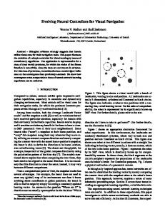
Figure 2. Example images from the panoramic camera (a); the transformed image fed to left side LGMD, the field of view is about 100 degrees (b); the image fed to right side LGMD, the field of view is about 100 degrees (c). There is 20 degrees overlapped area which covers the front part of the vision.
C. Image transformation Panoramic images captured by the robot’s CCD camera (Figure 2, top) is transformed into normal images (Figure 2 bottom) in real time before split and fed to the LGMDs. The transformation is done using a program written in Matlab® (Mathworks, USA). The transformation involves in rearranging pixels to a different coordination system, i.e., from a Polar to a Cartesian coordination system. The grey scale at each pixel remains unchanged after transformation. The size of the image fed to the left and right LGMDs are with 100 pixels in horizontal and 42 in vertical, covering 100 degree field of view in each side with 20 degrees overlapping area. The two wide range images fed to left/right LGMD should allow the system responding to the changing scenes in the front hemisphere. D. Implementation The LGMD neural networks and the motor command generator were written in Matlab® (MathWorks, USA) and
EXPERIMENTS AND RESULTS
To check the feasibility of the system, we put the robot at one end of an arena with two walls – one curved block wall on one side and sparse blocks on other side. The robot is expected to move for about 8 seconds and stop. We repeated the experiments several times with the robot started from different entrances of the arena; results are shown in Figure 3. We found that the vision system works well providing relevant information for the motor system to yield reasonable navigation paths between the two columns of blocks, although the initial positions and orientations of the robot in the above five trials were quite different, as indicated in Figure 3.
Figure 3. The navigation paths of the robot. Two trials with initial orientation towards one end of the arena surrounded by one curved blocks wall and several sparsely aligned blocks(left); three trials with initial orientation towards the other end of the path in the same environment as in the left side image (right). Images were from the first frame of two trials and trajectories were overlaid after being extracted from recorded video clips.
Experiments were also carried out to investigate the impact of individual object on the VISION system. Details of the two trails with or without a hand in the environment were shown in Figure 4 and Figure 5. The robot conducted a quite different movement (as evidenced from its path) when a hand was presented on its way (Figure 4). The difference of excitation from left and right LGMD at the two trials were shown in Figure 5, together with the outputs from the command generator to the left and right wheels. It was found that the robot changed its direction to its right side at the first part of the journey, and turn back to its left side at the last half of this journey when the hand was presented (Figure 5, a, left) by adjusting the speed of its left and right wheels (Figure 5, a, right). For the trial without hand on its path, the speed of the wheels performed differently, especially around the critical time from frame 10 to 30 (Figure 5, b).
Figure 4. The movement trajectories of the robot in two different trials, (left) without object on its path; (right) with an object – a hand, on its way. Image was from the first frame of each trial and trajectories were overlaid after being extracted from recorded video clips. Both of the trajectories were overlaid to the first frame of images for easy comparison.
0.3
12
speed value to each wheel
difference in excitation
left wheel
0.2 0.1 0 -0.1 -0.2 -0.3 -0.4 -0.5
0
10
20
30
40
50
8
6
4
2
0
60
frame
right wheel
10
0
10
20
30
40
50
60
frame
V.
(a) 0.4
speed value to each wheel
12
difference in excitation
0.3 0.2 0.1 0 -0.1 -0.2 -0.3
0
10
20
30
40
50
left wheel right wheel
10 8
6 4 2
0
60
0
10
20
30
40
50
60
frame
frame
(b) Figure 5. Left column, the difference in excitation between the left and right LGMD; right column, the different output speed to left and right wheels. (a) The trial with the hand in the environment (Figure 4); (b) the trial without the hand (Figure 4).
IV.
These sharp changes may bring difficulties in image interpretation or may further enhance unstable direction changes. However, our experiments showed that it was not a problem for motion sensitive neural network based vision system. With a simple motor system, the whole system worked well and stable. On the other hand, our experiments suggests a similar way of using extracted visual cues to direct fly course in a biological system may also be feasible. The presented LGMD based vision system picked up differential images only and computed the excitation level to guide the robot’s movements. It worked well regardless the complexity resulted from surrounding objects’ size, shape, colour or other physical characteristics. The robustness of these motion sensitive neural networks has been demonstrated in different applications (Yue and Rind, 2006, 2007). Therefore, the proposed system is ideal to be implemented to mobile robotic systems to enable basic local path planning. Flies demonstrated motor planning ability mediated by visual information in the escape responses (Card & Dickinson 2008). Elementary motion detector (EMD), which was proposed to explain a visual processing mechanism in fly (Hassenstein & Reichardt 1956), has also been applied to robots for navigation (e.g., Francessini 2004 and Harrison and Koch 2000) or as speed odometer to guide fly robots’ (Iida 2003). However, the EMD model can be limited to certain range of speed. It is not clear if an EMD model still works when the projected retinal image speed is faster than predicted. The presented LGMD based visual networks are able to respond to image changes in a whole visual field and accommodate large variety of retinal image speeds. With the presented system, faster optical flow results in stronger excitation, and therefore, causes bigger turning speed and acute movement that enables the robot to run away from the faster image change. In the future, we are going to combine a bio-inspired target tracking algorithm with the vision system to enable a mobile robot interact with dynamic world better.
DISCUSSIONS
Since the camera was mounted on the mobile platform, the constant movements and frequent direction changes should result in sharp changes between successive images.
CONCLUSION
In the above sections, we presented a binocular style vision system that enables a mobile robot exploring local paths effectively using visual input only. The vision system consists of a pair of LGMD visual neural networks and a simple motor system. The vision system shares the distinctive feature of motion sensitive neural networks – processing visual images effectively in real time regardless the colour, shape, physical characteristics of surrounding objects. Our experiments showed that the system worked well in different scenarios. The system can be further implemented to other mobile robot platforms for local path exploring, motion planning and interacting. ACKNOWLEDGMENT This research is partly supported by EU IST (FET) 200138097.
REFERENCES [1]
[2] [3]
[4]
[5] [6] [7] [8]
[9]
[10]
[11]
[12]
[13] [14]
[15]
[16]
[17]
[18]
[19]
[20]
Blanchard, M. Rind, F.C. & Verschure, P.F.M.J. Collision avoidance using a model of the locust LGMD neuron. Robotics and Automonous Systems, vol.30, 17-38. 2000. Buxton, H. Learning and understanding dynamic scene activities: a review. Image and Vision Computing, vol.21, 125-136, 2003. Card, G. & Dickinson, M.H. Visually mediated motor planning in the escape response of drosophila. Current Biology, vol.18(17), 1-8, 2008. DeSouza, G.N. & Kak, A.C. Vision for mobile robot navigation: a survey. IEEE Transactions on Pattern Analysis and Machine Intelligence, vol.24 (2), 237-67, 2002.
http://www.darpa.mil/grandchallenge/index.asp Fiala, M. & Basu, A. Robot navigation using panoramic tracking. Pattern Recognition, vol.37, 2195-2215, 2004. Franceschini, N. Visual guidance based on optic flow: a biorobotic approach. Journal of Physiology Paris, vol.98, pp281-292, 2004. Gandhi, T. and Trivedi, M.M. Redestrian protection systems: issues, survey, and challenges. IEEE Transactions on Intelligent Transport Systems, vol.8, no.3, 413-430, 2007. Harrison, R.R., & Koch, C. A silicon implementation of the fly's optomotor control system. Neural Computation, vol.12, 2291-2304, 2000. Hassenstein, B., & Reichardt, W. Systemtheorische analyse der zeit-, reihenfolgenund vorzeichenauswertung bei der bewegungsperzeption des ruesselkaefers chlorophanus. Zeitschrift fuer Naturforschung, vol.11b, 513-524. Huber, S.A. Franz M.O. & Buelthoff, H.H. On robots and flies: modelling the visual orientating behaviour of flies. Robotics and Autonomous Systems, vol.29, 227-242, 1999. Iida, F. Biologically Inspired Visual Odometer for Navigation of a Flying Robot. Robotics and Autonomous Systems, vol.44/3-4, 201208, 2003. Indiveri, G. & Douglas, R. Neuromorphic vision sensors. Science, vol.288, 1189-1190, 2000. Manduchi, R. Castano, A. Talukder A. & Matthies, L. Obstacle detection and terrain classification for autonomous off-road navigation. Autonomous Robots, vol.18, 81-102, 2005. Nishio, K., Yonezu, H., Kariyawasam, A.B., Yoshikawa, Y. Sawa, S. & Furukawa, Y., Anology integrated circuit for motion detection against moving background based on the insect visual system. Optical Review, vol.11, 1, 24-33, 2004. Olson,C.F., Matthies, L.H., Schoppers, M. and Maimone, M.W. Rover navigation using stereo ego-motion. Robotics and Autonomous Systems, vol.43, 215-229, 2003. O’Shea, M. Rowell, C.H.F., Williams, J.L.D. The anatomy of a locust visual interneurone: The descending contralateral movement detector. Journal of Exp. Biology, vol.60, 1–12, 1974. Rind, F.C. & Bramwell, D.I. Neural network based on the input organization of an identified neuron signaling impending collision. Journal of Neurophysiology, vol.75, 967– 985, 1996. Rind, F.C. Simmons, P.J. Orthopteran DCMD neuron: A reevaluation of responses to moving objects. I. Selective responses to approaching objects. Journal of Neurophysiology, vol.68, 1654–1666, 1992. Rind, F.C. & Simmons, P.J. Seeing what is coming: Building collision sensitive neurons. Trends in Neurosciences, vol.22, 215-220, 1999.
[21] Rind, F.C. Motion detectors in the locust visual system: from biology to robot sensors. Microscopy Research and Technique, vol.56, 256269, 2002. [22] Rind, F.C. Santer, R.D.J., Blanchard, M. & Verschure, P.F.M.J. Locust’s looming detectors for robot sensors. Sensors and Sensing in Biology and Engineering, FG Barth, JAC Humphrey, and TW Secomb (Eds.), Spinger-Verlag, Wien, New York, 2003. [23] Rind, F.C. Bioinspired sensors: from insect eyes to robot vision. Frontiers in Neuroscience: Methods in Insect Sensory Neuroscience, Christensen T.A. (Eds.), CRC Press Boca Raton, London, New York, 2005 [24] Rowell, C.H.F. O’Shea, M. Williams, J.L. The neuronal basis of a sensory analyser, the acridid movement detector system .IV. The preference for small field stimuli. J. Experimental Biology, vol.68, 157-185, 1977. [25] Santer,R.D., Simmons,P.J. & Rind, F.C. Gliding behaviour elicited by lateral looming stimuli in flying locusts. Journal of Comparative Physiology, vol.191, 61-73, 2005. [26] Schlotterer, G.R. Response of the locust descending contralateral movement detector neuron to rapidly approaching and withdrawing visual stimuli. Canadian Journal of Zoology, vol.55, 1372–1376, 1977. [27] Simmons, P.J., Rind, F.C. Orthopteran DCMD neuron: A reevaluation of responses to moving objects. II. Critical cues for detecting approaching objects. Journal of Neurophysiology, vol.68, 1667–1682, 1992. [28] Stafford, R., Santer R.D. & Rind, F.C. A bio-inspired visual collision detection mechanism for cars: combining insect inspired neurons to create a robust system. BioSystems, 87, 162-169, 2007. [29] Webb, B. & Reeve, R. Reafferent or redundant: integration of phonotaxis and optomotor behaviour in crickets and robots. Adaptive behaviour, vol.11 (3), 137-158. 2003. [30] Wichert,G. Can robots learn to see?. Control Engineering Practice, vol.7, pp.783-795, 1999. [31] Yue, S. & Rind, F.C. A Collision detection system for a mobile robot inspired by locust visual system. IEEE Int. Conf. on Robotics and Automation, Spain, Barcelona, Apr.18-21, 2005, 3843-3848, 2005. [32] Yue, S. & Rind, F.C. Collision detection in complex dynamic scenes using a LGMD based visual neural network with feature enhancement. IEEE Transactions on Neural Networks, May, vol.17 (3), 705-716, 2006. [33] Yue, S., Rind, F.C. Keil, M.S., Cuadri, J. & Stafford, R. A bioinspired visual collision detection mechanism for cars: optimisation of a model of a locust neuron to a novel environment. Neurocomputing, vol.69 (13-15), 1591-1598, 2006. [34] Yue, S. & Rind, F.C. Visual motion pattern extraction and fusion for collision detection in complex dynamic scenes. Computer Vision and Image Understanding, vol.104 (1), 48-60, 2006b. [35] Yue, S. & Rind, F.C. A synthetic vision system using directionally selective motion detectors to recognize collision. Artificial Life, vol.13 (2), 93-122, 2007. [36] Yue, S., Santer, R., Yamawaki, Y., & Rind F.C., Locust-like emergent escape behaviour of mobile robots emerged with bilateral pair of visual LGMD/DCMD, Autonomous Robots, 2007 (under review). [37] Yue. S. & Rind, F.C. Competence comparison of collision sensitive neural systems in dynamic environments. Artificial Life, 2008a (under review). [38] Yue, S. & Rind, F.C. Exploring organization of direction selective neural networks for road collision prediction. IEEE Trans. Intelligent Transport Systems, 2008b (under review).