14. Coding tree VS. MILP. Algorithm 2 ModTree(u,x). 1: Connect u to x, this will create a cycle, say C. 2: Traverse the nodes on the cycle, until we reach a node in.
1
Network Coding-Based Protection of Wireless Mesh Networks
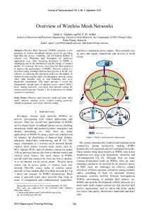
I. I NTRODUCTION Wireless mesh networks (WMNs) have recently emerged as a convenient solution to provide last-mile service, where they can be deployed as community or metropolitan networks to grant Internet access to endusers. WMNs are composed of two types of nodes: the wireless mesh routers that are usually organized to establish an infrastructure or a backbone that serves the second type of nodes, which are the clients. In contrast to traditional infrastructure wireless networks, not all routers need to be connected directly to the wired network to access Internet. This is because WMNs allow direct wireless communication between routers, hence enabling unconnected routers to access the Internet through multi-hop communication with the connected ones. The latter routers are commonly referred to as gateways (an illustration is shown in Fig.1). Since the data flow on a WMN is mainly Internet related, one important characteristic of the flow is that it takes one of two main structures, either a one-to-many flow from a certain gateway to a certain set of users or routers, or a many-to-one flow from the routers to the gateway.
I
L
L
L
1
2
3
t
r
y
a
e
w
t
e
u
t
r
e
e
n
n
R o
G a
r
U s
Fig. 1.
e
Abstract—Survivability of wireless mesh networks (WMN) is an important issue that has not received enough attention in the literature. Traditional proactive and reactive protection schemes are either resource-hungry like the (1+1) protection scheme, or introduce a delay and interrupt the network operation to recover from failures, such as the (1 : N ) protection scheme. In this paper, we introduced a novel approach that relies on network coding to provide protection to many-to-one flows in WMNs at the speed of proactive protection, but at the cost of reactive protection. We derive and prove the necessary and sufficient conditions for our solution to exist on a restricted network topology. Then we introduce two generalizations of our problem, and provide a heuristic and a mixed integer linear program (MILP) to solve one of them. We also show that deterministic coding with {0,1} coefficients is enough in our case under some conditions. Finally, we discuss some practical considerations related to our approach, and define a more general problem that takes these considerations into account. We also formulate this general problem as an MILP.
t
Osameh M. Al-Kofahi Ahmad E. Kamal Department of Electrical and Computer Engineering, Iowa State University
Wireless Mesh Network
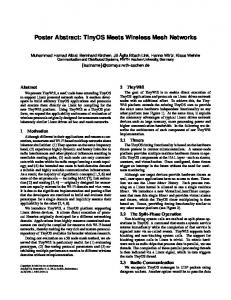
The wireless communication medium in WMNs is susceptible to various types of interference, which causes the link status to dynamically change according to the channel conditions, hence resulting in information loss. To mitigate the effects of this problem, various schemes to enhance the survivability of wireless networks were presented. These methods can be divided into three main classes, 1) protection schemes [1][2][3][4][5][6]. 2) restoration schemes [7][8], and 3) hybrid schemes [9][10]. Protection schemes reserve backup resources in advance and can be divided into two main categories: 1) Proactive protection, viz., 1+1 protection, where each source sends two copies of its data unit on two edge-disjoint paths to the sink, so that if a link on one of the paths fails, the sink receives another copy on the other path. This is a very resource demanding solution, because we need at least twice as many resources. This makes this approach hard to realize. For example, in the network shown in Fig.2(b), there are two sources, S1 and S2 , sending two data units, b1 and b2 , respectively to a sink node T . Since the minimum-cut between the sources and the sink is 3, each source must use the network in a different time slot to be able to tolerate a single-link failure, i.e., to have two edge-disjoint paths to the sink. 2) A less demanding solution is to use reactive protection, viz., 1:2 protection, where each source uses a primary path to the sink that is edge disjoint from the
2
other primary paths used by other sources, and one extra path is reserved to be used by any of the sources if a failure occurs, as shown in Fig.2(c). In this case, if a failure takes place on one of the primary paths. The affected source will have to detect the failure, and then reroute its data to use the backup path. This introduces delay and interrupts network operation. Restoration schemes are feedback-based, since they only get into action after detecting a failure or a missing packet and then they start to discover the available resources, which introduces some delay in the recovery process. Hybrid schemes resort to restoration when protection fails. In this paper, we take a first step toward utilizing network coding [11][12][13] to provide protection in a proactive manner in many-to-one flow networks, the main advantage of using network coding lies in reducing the required resources to provide such protection. As far as we know, using network coding in this direction has not been explored yet. The rest of this paper is organized as follows. Section II, describes the problem, and states the paper contributions. In Section III, we discuss the sufficient and necessary conditions for our solution to exist. Section IV provides a mixed integer program to solve one of the general cases introduced at the end of Section III. In Section V we discuss how to perform coding using {0, 1} coefficients. In Section VI, we discuss some of the practical issues related to our solution. Finally, we conclude the paper in Section VII. II. P ROBLEM D ESCRIPTION We consider a WMN, in which there is only one gateway, and in which the routers can be organized in t levels, where the routers in level i (or Li for short) are i hops away from the gateway. For example, the network in Fig.1 has 3 levels of routers. We assume that the t levels access the wireless medium in a TDMA manner, where each level of routers is assigned a different time slot, that is used to send data units from those routers. In general, we assume that there are n source nodes in the network, which represent the routers in a certain level, say Ls , in their assigned time slot. We assume that there are n data units that need to be sent from the n routers to a single sink node. Fig.2(a) shows a network with two source nodes. Our objective is to provide protection at the speed of proactive protection, but at the cost of reactive protection. We achieve this by using network coding. Suppose we allow node A in the network shown in Fig.2(a) to combine b1 and b2 (bitwise XOR), and send the resulting symbol to the sink on the link (A, T ), as illustrated
in Fig.2(d). This way, the two sources can use the network in the same time slot and still achieve proactive protection. If any of the three symbols sent to the sink is lost due to a link failure, the sink will still be able to recover the original data units. For example, assume that link (S2 , C) fails, the sink will receive b1 ⊕ b2 on link (A, T ) and b1 on link (D, T ), and it can recover b2 by performing the bitwise XOR operation on the received symbols. Specifically, the contribution of this paper lies in answering the following questions: • How can network coding be used to provide protection against link (or path) failures in such manyto-one flow networks, while using the minimum possible number of paths? • What are the necessary and sufficient conditions for such a solution to exist? III. P ROPOSED APPROACH A. Assumptions, Definitions and Notation There are two modes of communication in WMNs, either one-to-many where the flow is directed from the gateway to the routers in Li , or many-to-one where the flow is directed from the routers in Li to the gateway. Since we are only considering the case of many-toone flows, we can adopt the directed graph model in which a graph G(V, E) is used to represent the network, where the set of vertices V represents the network nodes, and the set of edges E represents the available wireless links between the network nodes, such that the edges are always directed from levels with higher indices to levels with lower indices. Taking that into account we define the following: 1) Let Ls be the set of routers in the level being considered, where |Ls | = n. 2) Let T be the only sink node in the network. 3) Let Ls−1 be the set of one-hop neighbors of all the sources in Ls . Where |Ls−1 | ≥ n + 1. 4) All the links in the original graph G are of unit capacity, and there are no parallel links. 5) The maximum-flow between the nodes in Ls−1 and the sink node T is ≥ n + 1. Later in this paper we will discuss networks that do not have this property. 6) The sub-graph induced by the nodes in Ls and Ls−1 is bipartite, i.e., there is no link with both ends belonging to Ls or to Ls−1 in the original graph G. We will consider general cases later in this paper. 7) Only one link fails at a time. 8) GT01 is the graph formed by: the nodes in Ls and Ls−1 and all the links between them, a hypothet-
3
b2
Time Slot 1
b1 S2
S1
Primary Path
Time Slot 2
b2 S2
b2
Backup Path
b2
S1
b1
b2
b1
S2
b2
b1
b1 S1
S2
S1
b1
b2
A b2
A
b1
C
A b2
b2
b1
b2
b1
b1
D
C
(a)
b1 D
D b2
b1 T
b1+b2
b1 C
C
Fig. 2.
b2
b2
D b2
b1 A
b2
T
b1
(b)
b2
T
b1
(c)
b1 T
(d)
(a) Original graph (b) 1+1 Protection, (c) 1:2 Protection, (d) Network coding Protection
ical sink node T 0 and hypothetical links from all the nodes in Ls−1 to T 0 . 9) GST 01 is the graph formed by: the nodes in Ls and Ls−1 , and all the links between them, with a capacity of n assigned to each of these links, a hypothetical sink node T 0 , hypothetical links with capacity of n from all nodes in Ls−1 to T 0 , a hypothetical source node S 0 and hypothetical links with capacity of n+1 from S 0 to the nodes in Ls . As an illustration of points 8 and 9 above, a simple graph is shown in Fig.3, and its corresponding GT01 and GST 01 are given in Fig.4 and Fig.5 respectively. In these figures S1 , S2 and S3 are the nodes in Ls , and A, B , C and D are the nodes in Ls−1 . B. Overview The basic idea of our approach is to create n+1 linear combinations (equations) from the n original data units, using deterministic coding, such that, any n of them are linearly independent (solvable), and then forward these combinations to the sink using n+1 edge disjoint paths, assuming such paths exist. This way, the sink will be able to recover the original n data units even if one of the combinations is lost due to a link failure, without the need to detect the failure or to use different time slots for each of the sources. This is illustrated in Fig.2(d), where redundant data units are sent to node A, which created the combination b1 +b2 , making a total of three linear combinations, such that any two of them are linearly independent. Thus, the sink can recreate the original data units if it receives at least two of the combinations. C. Solution Details In this subsection we do not consider the details of coding, we only focus on the needed information content in the linear combinations that will enable the sink to recover the original n data units upon a failure. Thus, in this subsection we always assume that the
created combinations are linearly independent, and we will elaborate more on coding in Section V. We assume that only one level of routers, Ls , is active at a certain time, and our goal is to use deterministic network coding to provide proactive protection for the n sources in that level. Under assumption 6, coding cannot begin in sources, since each of which only knows its own data. Hence, creating the n + 1 combinations is the responsibility of the intermediate network nodes that connect the sources to the sink. We only consider the closest nodes in the intermediate network to Ls that can perform coding on the data units from the sources in Ls , which are the nodes of Ls−1 that are only one hop away from the nodes in Ls . We assume the worst case scenario that occurs when |Ls−1 | = n + 1, i.e., each one of the nodes in Ls−1 is responsible for producing one linear combination and forwarding it to the sink. From assumption 5, our original graph G can be replaced with GT01 . Taking this transformation into account, the condition that will enable the Ls−1 nodes to construct the n + 1 combinations that can tolerate a single link or path failure is: Condition: Any k nodes in Ls , are connected to k + 1 nodes in Ls−1 : Consider the network in Fig.6, if either of the links AT or BT fails, the sink will not be able to recover all three data units, because the other link that did not fail will be carrying the only combination of the two data units b1 and b2 , while the sink needs at least two. Regard the linear combination created in a node v in Ls−1 . There are n possible participants that can contribute to creating this linear combination. Let us assume that the combination consisted of two data units (i.e. v is connected to two source nodes in Ls ). Then the sink can recover the two data units upon the failure of the path from node v if these two symbols were present in at least two other equations such that there are n independent equations in n unknowns. That is, if node v is connected to k nodes in Ls , then for the
4
S
’
S2
4
2
2
3
3
3
3
3
A
b3
3
3
B
D
C
B
C
M 3
L
S2
2
1
S 2
3
K
b2
S1
D A
J
b1
S
S 1
I D
H
C
G
B
F
A
E
b3 S3 S
D S
C
3
B
S
A
4
S2
4
S1
’
T
’
b3 T
T’
T’
Fig. 3.
The original graph G
Fig. 4.
Graph GT01
sink to be able to recover all the original data units if the combination created in v is lost, the neighboring set in Ls−1 which encode data units from the k nodes in Ls must be of size that is at least k , or k + 1 if we include v . In general we can say: Any group of nodes in Ls of size k must be connected to at least k +1 nodes in Ls−1 . Using the concept of matching in graph theory, an equivalent statement would be: n + 1 perfect matchings between the nodes in Ls and those in Ls−1 must exist, such that each matching, Mi , corresponds to the case when one of the nodes in Ls−1 , vi , is removed, where 1 ≤ i ≤ n+1. This guarantees the existence of a working path from every source node to the sink upon a single link failure. This condition implies that the Max-flow is greater than or equal to 2 from every source to the sink. We now continue with proving that this condition is necessary and sufficient for the nodes in Ls−1 to be able to construct the n + 1 combinations that can tolerate a single link (or path) failure. Theorem 1. The sink will be able to recover the n data units even if ANY one from the n+1 combinations is lost, if and only if, any subset of Ls of size k is connected to a subset in Ls−1 of size at least k + 1, where 1 ≤ k ≤ n. Proof. In the previous scenario we view the data units from sources as variables, and the n + 1 nodes in Ls−1 as combinations (or equations), and a variable is present in an equation if the corresponding source is connected to the node in Ls−1 representing that equation. We prove the implication by contradiction. Assume that the sink is able to recover the n data units, even if ANY one from the n + 1 combinations is lost. Then, let there be a subset of Ls nodes of size k , that is connected to a subset of Ls−1 nodes of the same size k . Then, the sink cannot randomly choose n combinations from the n + 1, because it MUST pick the k combinations that were just mentioned; otherwise, the k variables from the corresponding k nodes in Ls will only be present in k−1 equations, which means we cannot recover them. This contradicts the assumption that the sink is able to recover the original n data units if ANY of the combinations was
Fig. 5.
Graph GST 01
Fig. 6. If link AT fails the sink can not recover the data
lost, which concludes the proof of the implication. To prove the converse, we also use contradiction. Assume that any subset of nodes in Ls of size k is connected to another subset of nodes in Ls−1 that is of size at least k+1. But, there is a mandatory combination, which cannot be lost for the sink to be able to recover the original n data units. A combination is essential and can not be lost, if it leaves a set of equations of size say l with l+1 unknowns, that are impossible to solve without the combination. But for this case to happen, there must have been some l+1 nodes in Ls that are only connected to l + 1 nodes in Ls−1 , which contradicts our original assumption, of having any k nodes in Ls connected to at least k + 1 nodes in Ls−1 , where 1 ≤ k ≤ n.¥ It can be seen that a naive check for the above condition takes time of order O(2n ). We will now show how to check the condition above in polynomial-time with respect to the number of sources using a maxflow algorithm. We will use the graph GST 01 in our next theorem. (see Section III-A, bullet 9 for definition). Theorem 2. An S-T maximum-flow of n(n + 1) is achievable in GST 01 , if and only if, any subset of Ls of size k is connected to a subset in Ls−1 of size at least k + 1, where 1 ≤ k ≤ n. Proof. We prove the implication by contradiction. Assume the max-flow value is indeed n(n + 1), then all the incoming links from S to the n original sources are saturated (i.e. each one carries a flow equal to n+1). And assume that there are some k nodes in Ls that are only connected to k other nodes in Ls−1 . The incoming flow to this component equals k(n + 1) = kn + k while the outgoing capacity equals kn, which means that there are k units of flow that will be blocked from the sink, that is the max-flow = n(n + 1) − k which contradicts the original assumption of the max-flow. We prove the converse by contradiction. Suppose that any k nodes in Ls are connected to at least k + 1 nodes in Ls−1 , but the maximum achievable flow was less than n(n+1), then there are some of the incoming links from S to the nodes in Ls that could not be saturated. Assume only one of those links carried just n units of flow to a
5
node in Ls say node u, then node u either has a single outgoing link, or is one of k nodes in Ls , that are only connected to another k nodes in Ls−1 (because if it was not the case, then it would have been able to forward this remaining unit of flow to the sink through an augmenting path on the residual network), in both cases node u will violate the connectivity assumptions. Therefore, the maxflow must be n(n + 1). This concludes the proof. ¥ D. Generalizations 1) A Larger Ls−1 : Until now, we have assumed that the number of nodes in Ls−1 is exactly n+1. The number of Ls−1 nodes could be much larger than n + 1. This however, does not invalidate our approach and the above requirements will still apply. The only difference is that the number of minimum linear combinations may be more than n + 1, depending on the topology of the graph. One simple example, is when each of the n sources is connected to exactly two nodes in Ls−1 , and each of the Ls−1 nodes has exactly one node as a neighbor in Ls . That is, |Ls−1 | = 2n. Assuming that the max-flow from Ls−1 to the sink is 2n, the minimum number of required linear combinations that can tolerate a single link failure in this case is 2n, which will be equivalent to 1 + 1 protection, where coding is not needed and routing can be used. Another issue that rises in this case is selecting the appropriate linear combinations that will enable the sink to recover all the original data units. The network shown in Fig.7 gives a good example, where the minimum number of combinations is n + 2. In this network, picking 4 combinations randomly may not cover all the data units. For example if the combinations created in nodes C , D, E and F were chosen by the sink to calculate the original four data units, b1 cannot be recovered. However, if any of the above mentioned four combinations was replaced by either of the combinations produced in A or B , the sink will be able to recover all the original data units. Thus, choosing combinations randomly when the minimum number of combinations is larger than n+1, may not result in choosing a collection of combinations that will enable the sink to decode and recover the original n data units. We conjecture that the problem of finding the minimum number Ls−1 nodes that satisfies the connectivity conditions, and hence, the problem of finding the minimum number of linear combinations that can tolerate a single link failure is NP-Complete. We therefore formulate a solution to this problem as a mixed integer program in Section IV. 2) General Network Topology: Assumption 6 in section III-A states that the graph induced by the nodes
in Ls and Ls−1 is bipartite. This is a very restricted topology that may not be present in a real network. Therefore, below we address in our solution the problem of adapting to other network topologies. By carefully inspecting the condition of Theorem 1, one can see that the essence of the solution lies in the number of edge-disjoint paths from a group of sources to the sink. In the special case considered previously, each node in Ls−1 had at least one such path. Theorem 1 can be generalized in the following corollary. Corollary 1. The sink will be able to recover the n data units even if ANY one from the n + 1 combinations is lost, if and only if, any subset of Ls of size k is connected to the sink through a set of edge-disjoint paths of size at least k + 1, where 1 ≤ k ≤ n. Proof. The proof of this corollary is straightforward, and follows directly the same reasoning used in proving Theorem 1. ¥ As an example to illustrate Corollary 1, consider a less restricted network topology, where we allow a source to be in the Ls−1 neighborhood of another source node, as shown in Fig.8. Table I lists a collection of edge-disjoint paths between every possible combination of sources and the sink. It can be easily verified that the network in Fig.8 satisfies the condition in Corollary 1. TABLE I E DGE - DISJOINT PATHS BETWEEN COMBINATIONS OF SOURCES AND SINK IN F IG .8
Sources S1 S2 S3 {S1 , S2 } {S1 , S3 } {S2 , S3 } {S1 , S2 , S3 }
Paths {S1 -A-T }, {S1 -S3 -B-T } {S2 -D-T }, {S2 -S3 -C-T } {S3 -B-T }, {S3 -C-T } {S1 -A-T }, {S1 -S3 -B-T }, {S2 -D-T } {S1 -A-T }, {S1 -S3 -B-T }, {S3 -C-T } {S2 -D-T }, {S2 -S3 -C-T }, {S3 -B-T } {S1 -A-T }, {S2 -D-T }, {S3 -B-T }, {S3 -C-T }
IV. M IXED I NTEGER L INEAR P ROGRAM F ORMULATION Continuing on the problem of finding the minimum number Ls−1 nodes that satisfies the connectivity condition that was introduced in Section III-D1, we use the graph GST 01 to formulate an MILP to calculate the minimum number of paths that are needed from nodes in Ls−1 to the sink, in order to forward n(n+1) units of flow. Since we assume that each Ls−1 node has a single path to the sink (that is edge-disjoint from the paths used by other Ls−1 nodes), calculating the minimum number of paths will result in the minimum number of nodes
6 b1 b1
b2 S1
b3 S2
b2
b4 S3
S1
S2
S4
b3 S3
A
B
C
D
E
F
b1
b2+b3
b1+b3
D b1+b3
b4
b2
C
A b3
b4 + b2
b3+b2
b2+b1
b1
B
b2+b3 b2
b1 T
Fig. 7.
Minimum n+2 combinations
Fig. 8.
in Ls−1 that satisfies the connectivity conditions, and hence, the minimum number of linear combinations that can tolerate a single failure. A. Notations • • • •
•
Non-bipartite topology
X
yv −
Let m be the number of nodes in Ls−1 . Nyx (z) is the set of level y neighbors of node z , such that z is in level x, where x and y ∈ {s, (s − 1)}. fuv and cuv corresponds to the flow and capacity of edge (u, v), respectively, where 0 ≤ fuv ≤ cuv . cS 0 u equals n+1 where S 0 is the hypothetical source node and u ∈ Ls . The capacity of all other edges equals n. yv is defined for every node v in Ls−1 and it equals the sum of all flows going through that node X fuv yv =
fuv = n + 1, ∀u ∈ Ls
(3)
∀v:v²N10 (u)
X
fuv = 0, ∀v ∈ Ls−1
(4)
∀u:v²N10 (u)
These two constraints represent the conservation of flow constraints, where the first one beside conserving the flow assures that the links from the hypothetical source to all the nodes in Ls are saturated to guarantee a max-flow of n(n + 1). And, the second one (combined with the bounds on yv below) simply says that the sum of all incoming flows to a certain node v in Ls−1 cannot exceed the capacity of the single outgoing link to the sink. Finally the following two bounds are needed: 0 ≤ fuv ≤ n, ∀(u, v)
(5)
0 ≤ yv ≤ n, ∀v
(6)
∀u:v∈N10 (u)
•
where 0 ≤ yv ≤ n, and v = 1, 2, ..., m zv is a binary variable, which is equal to 1 if the outgoing link from v to the sink forwards flow, i.e.: ½ 1 if 0 < yv ≤ n zv = 0 otherwise
B. MILP Formulation We begin with the assumption that the maximum achievable flow from S 0 to T 0 is n(n + 1). All the nodes in Ls−1 that participate in the flow are selected to be the coding nodes. We calculate the minimum number of Ls−1 nodes that satisfy the connectivity conditions, by calculating the minimum number of used paths. The objective function is: M inimize
m X
zv
(1)
v=1
Subject to: zv −
yv ≥ 0, ∀v ∈ Ls−1 n
(2)
This constraint is defined for every node v in Ls−1 , and it sets the binary variable zv to 1 if there is an outgoing flow from node v to the sink T 0 .
For u ² Ls and v ∈ Ls−1 . V. C ODING In the previous sections, we assumed linear independence between linearly combined data units. In this section, we will show how to achieve this independence between combinations through using {0, 1} coefficients. A linear combination is a summation of data symbols (bi ’s) each of which is multiplied by a coefficient P c(αi ) k c from a finite field GF (2 ), as follows: C = i αi .bi , where αi ∈ GF (2k ). The independence of combinations relies on the bi ’s and the choice of the αi ’s. Therefore, achieving independence using {0, 1} coefficients depends solely on how we compose each combination from only the data units. For instance, in Fig.2(d), the three combinations that were sent to the sink are, C1 = b1 , C2 = b2 and C3 = b1 + b2 . The coding in this example can be expressed using matrices by: ¶ 1 0 µ C1 b1 M.b = 0 1 = C2 = C b2 1 1 C3
7
Where M is the coding matrix, and each row in it is the coding vector for the corresponding combination. In the following subsections, we presume that assumption 6 in Section III-A and the connectivity condition of Theorem 1 are satisfied, and we show how to decide on the data units composing each of the linear combinations, through finding simple paths and trees. A. The benefits of paths and trees Consider a single path, in the bipartite graph induced by the nodes in Ls and Ls−1 , that starts from a node in Ls−1 and ends at a different node also in Ls−1 , and in the middle it alternates between Ls and Ls−1 until it covers all the nodes in Ls . It can be easily verified that any k nodes from Ls on that path have at least k + 1 neighboring nodes from Ls−1 also on that path. To illustrate the benefits of coding according to the connectivity on a path, consider the example in Fig.9, where we have 4 source nodes in Ls , and 5 nodes in Ls−1 . If we let all the sources use all their outgoing links to Ls−1 as shown in the example, we will have dependent combinations like {b4 + b3 } and {b4 + b3 } (or {b1 + b2 } and {b1 + b2 }), thus invalidating the linear independence requirements. b1
b2 S1
b3 S2
b4 S3
S4
A
B
C
D
E
b1 + b2
b1 + b2
b4 + b3+b2+b1
b3 + b4
b3 + b4
Fig. 9. Bad coding: linear Independence of any n combinations is not satisfied
However, consider the simple path {A, S1 , B, S2 , C, S3 , D, S4 , E} that is represented by the solid edges in Fig.10. If we compose the linear combinations at the Ls−1 nodes according to their connectivity with the nodes in Ls on the path, i.e., a solid line correspond to a coefficient of 1 and a dashed line correspond to a coefficient of 0. Linear independence will be guaranteed, since there cannot be two (or more) nodes in Ls−1 that are connected to the same nodes in Ls on a simple path. b1
b2 S1
A
b1
b3 S2
b4 S3
S4
B
C
D
b1 + b2
b3+b2
b3 + b4
E
b4
Fig. 10. Path coding: linear independence is satisfied in any n combinations
Of course, we may not always find a simple path that goes through all the nodes in Ls and has both of its ends
in Ls−1 . However, since a path is a special case of a tree with two leaves, then if we can find a tree that covers all the nodes in Ls , with all of its leaf nodes in Ls−1 , such that a node in Ls has at most one leaf neighbor, we can construct independent linear combinations according to the connectivity on the tree. This is shown in Fig.11(a), for the network presented in Fig.9, Fig.11(b) clarifies the underlying tree structure.
B
b1
b2 S1
b3 S2
D
b4 S3
b2
S4
b3
S2
S3 C
A
B
C
D
b1
E
S1
b1
b2
b4 + b3+b2+b1
b3
b4 S4
b4 A
(a)
E
(b)
Fig. 11. (a) Tree coding: linear independence is satisfied in any n linear combinations, (b) Underlying tree
It is guaranteed that there are no two or more coding vectors (matrix rows) with ones at the same positions, because if this was the case, this means that there are two or more nodes in Ls−1 that are connected to the same nodes in Ls , which produces a cycle that can not exist in a tree. In the next subsection we will show how to create a tree that satisfies the previous conditions efficiently. B. Constructing a coding tree We begin by constructing a Depth-First Search tree (DFS-tree) rooted at a node in Ls−1 , then we modify its structure to guarantee that there are no leaves in Ls . Finally we trim the extra Ls−1 leaves if any. A DFS-tree can be constructed in time of order O(|E|), and the trimming can be done in time of order O(|V |). The non-trivial part is modifying the structure of the tree to guarantee that there are no Ls leaves. Algorithms 1 and 2 describes a procedure to do the modification. Algorithm 1 Construct a coding tree 1: while there are leaves from Ls do LIST = φ 2: 3: Pick a leaf node from Ls in the tree, say u Find one of u’s neighbors say x {other than its parent} 4: 5: LIST = LIST ∪ {u, x} 6: Call ModTree(u, x) 7: end while
In Algorithm 1, we search the tree for a leaf node u that falls in Ls . Upon finding such a leaf node, we
8
C
C
A
C
A
A
w
w
1
A
1
C
2
S1
w
2 w
v
2 v
S1
2
B
B
B S1
S1
I
L
S
P
V
M
d
i
t
C
r
g
e
n
o
e
D
D
0
d
8
L
s
-
1
n
1
S2
v
1
S2
v
S2
S2
o
d
1
e
s
2
D
1
x
D
x
C2
E
E
S3
S3
S3
S3
6
E
s
L
N
e
o s
Fig. 12. The original network with 3 source nodes
Fig. 13. (a) DFS-Tree, (b) Nodes found in two iterations, (c) Making the modification, (d) Result after trimming extra leaves
Algorithm 2 ModTree(u,x) 1: Connect u to x, this will create a cycle, say C 2: Traverse the nodes on the cycle, until we reach a node in
3: 4: 5: 6: 7: 8: 9: 10:
Ls , say node v, that has a neighbor w not on the cycle, such that u and w ∈ / LIST if w is already connected to v then Cut the cycle directly before or after v return else Cut the cycle before or after v LIST = LIST ∪ {v, w} Call ModTree(v, w) end if
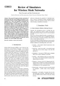
look for a neighbor x for this node that is different from its parent, we are guaranteed to find such a neighbor x, because each single node in Ls is connected to at least 2 nodes in Ls−1 (Theorem 1). After finding u and x, the procedure ModTree adds the link between them to the tree creating a cycle C . Then, it traverses the nodes on C to find a node v in Ls that has a neighbor w in Ls−1 not on C . Again, we are guaranteed to find such a node v that has such a neighbor w, because any k nodes in Ls are connected to at least k + 1 nodes in Ls−1 , and since the cycle is composed of equal number of nodes from both Ls and Ls−1 , then there must be a Ls node on this cycle that has a neighbor in Ls−1 not on the cycle. If v was connected to w on the tree, we cut the cycle before or after v , to make the graph a tree again. On the other hand, if v and w are not connected on the tree, we exclude them from our future choices and we recursively call ModTree until we find a suitable v and w, which is guaranteed to happen because of the imposed connectivity conditions. As an illustration consider the network in Fig.12, the resulting DFS-Tree rooted at node C is shown in Fig.13(a). The nodes that will be found when running Algorithm 1 and two
Fig. 14. MILP
Coding tree VS
iterations of ModTree are shown in Fig.13(b), the cycles and the edges that are marked to be cut are shown in Fig.13(c), and the final result after trimming the extra leaf nodes is shown in Fig.13(d). There can be at most n−1 Ls leaves, and the recursive call to ModTree can be done at most n times. Hence, the running time of Algorithm 1 is of order O(n2 ). To see how well this algorithm performs, in terms of needed number of Ls−1 nodes, we compared it to the MILP presented in Section IV, the results are shown in Fig.14. Each point on the graph corresponds to the average over 100 random topologies with the same number of nodes in Ls and Ls−1 , where we varied the number of Ls nodes from 2 to 10 with keeping the number of Ls−1 nodes twice as many. VI. P RACTICAL C ONSIDERATIONS A. Networks with limited minimum cuts In our previous discussion, we only considered the nodes in Ls and Ls−1 , and ignored the rest of the network, where we assumed that the Ls−1 nodes can forward each of the formed combinations on an edgedisjoint path to the sink. In practice, this may not be the case, thus, in this section we study networks with limited min-cuts. What concerns us in the rest of the network is the maximum number of edge-disjoint paths between the nodes in Ls−1 and the sink, which equals the minimum edge cut between Ls−1 and the sink (from Menger’s theorem [14]). Let the number of these edges be h. If h is greater than or equal to n + 1, then our approach can be applied directly, and the combinations formed in Ls−1 can be forwarded to the sink. On the other hand, if h is less than the minimum number of required edgedisjoint paths, then the formed combinations cannot be forwarded as is, and must be modified.
0
1
9
8
7
6
5
4
(d)
3
(c)
2
(b)
E
i
T r
g
d I
e
C
D
P
M
C
d
B
e
o e b m
4 u n
g
e
(a) A
0
A
v
2
e
r
a
S3
u
S2
u
S1
n
r
o
f
E
n
e
e
d
e
C1
9
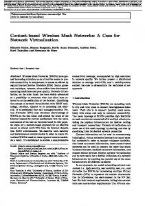
Assume that the minimum edge cut between Ls−1 and the sink is h, and is less than the required number of edge-disjoint paths. Then the maximum number of sources that can be protected together at the same time is h − 1. Therefore, we propose to divide the n sources into groups of size h − 1, and then choose a set of feasible groups that covers all the sources, where we assume different groups are time multiplexed, i.e., only one group is active at a time. A group of sources is said to be feasible if it can create h combinations that can tolerate a single link failure, i.e., if it satisfies the condition in Corollary 1. A set of groups covers all the sources, if each source is present in at least one of the feasible groups in the chosen set. To illustrate the idea consider the simple network in Fig.15 that contains 4 sources. One can see that the maximum number of edge-disjoint paths, from Ls−1 to the sink in this network is 3, i.e., h = 3. Hence, the largest possible group of sources, that can be protected together, will be of size at most 2. The number of possible groups is equal to 6, to be specific, there are 3 feasible groups: 1){S1 S2 }, 2){S1 S3 } and 3){S1 S4 }, and 3 infeasible groups: 4){S2 S3 }, 5){S2 S4 } and 6){S3 S4 }. Therefore, to cover all the sources, the first three groups must be picked, which means, 3 time slots must be used for all the sources to transmit. In the previous example, groups 1, 2 and 3 were the only possible subset of groups of size 2 that cover all the sources. Clearly, this is not a fair solution, because S1 is in all groups, and is allowed to transmit in all three time slots, i.e, transmitting at a rate of 1 symbol/time slot, while each of the remaining sources is allowed to transmit only in one of the three time slots, i.e, transmitting at a rate of 31 symbol/time slot. The solution could have been more optimal (fair), if there was a link between the nodes C and F . This is illustrated in the network in Fig.16. One can see that all the groups are feasible now, according to Corollary 1. It is obvious that the previous solution is still valid, but it is not optimal any more, since, for example we can choose groups 3 and 4, and not only cover all the sources, but also achieve better fairness, where the bandwidth is equally divided and all the sources transmit at a rate equal to 12 symbol/time slot. Fairness is not the only measure for the optimality of the chosen groups. The used network resources should also be taken into account. Keeping this in mind, and by carefully inspecting the network in Fig.16, we can see that groups 3 and 4 are not the most optimal choice, because each group uses 4 links to forward data from Ls−1 to the minimum cut edges, while we can choose groups 1 and 6, where each of which only uses 3 links to
forward data to the minimum cut edges. To summarize, the optimality of our choice of groups that covers all the sources is determined by: 1) The degree of disjointedness of the chosen groups: This affects fairness between sources and the minimum number of groups that could possibly be chosen, which plays an important role in determining the rate. The minimum number of groups that can cover all the sources is dn/(h−1)e,if all the groups are disjoint, except maybe for one group, when n does not divide perfectly by h−1, like groups 1 and 6 (or 3 and 4) in the network in Fig.16. And, an upper bound on the minimum number of groups to be chosen is n − h + 2, where in this case, the groups will not be disjoint. On the contrary, they will only differ in one source node each time, e.g., groups 1, 2 and 3 in the network in Fig.15. 2) The degree of resource utilization: which is affected by a)where the coding takes place, and b)the network topology, which governs the paths each source uses to reach the minimum cut. The amount of required resources is influenced by the number of paths or links used to forward data from Ls−1 to the sink, which in turn, is affected by the number of data units, since each path or link carries only one (possibly encoded) symbol. Thus, it is better for the coding to be in Ls−1 , and not in the tail nodes of the minimum cut edges, because, data units will be combined by coding, and this MAY decrease the required number of symbols to be transmitted from Ls−1 to the sink, e.g., the case of groups 1 and 6 shown in Fig.17, where all coding is done in Ls−1 . The problem of choosing the suitable set of feasible groups to cover all the sources can be proved to be NP-complete through a reduction from the K-Set Cover problem. We omit the proof because of space limitations. B. MILP Formulation In this subsection we formulate the Source-Grouping problem as a mixed integer program. For convenience, we define the following: 1) sk source number k 2) h minimum cut between L0 and the sink 3) C the maximum number of groups which equals n−h+2 4) fijkc the flow of source k in group c on edge (i, j) 5) gck a binary variable which is equal to one only if source k was in group c Assuming that the capacity of all edges is h − 1, the linear program is: M inimize
n X C X k=1 c=1
gck
(7)
10 b1 b1
b2 S1
b3
b4
S2
S3
b2 S1
B
b1
b4 S3
C
D
b3 S2
b4 S3
S4
B
C
D
E
A
F G
B
C
D
E
b3 +b4
b4
E b1
F
b2 S1
S4
S4 A
A
b3 S2
G
b1 +b2 F
H
H
b3 G
b1
b1 +b2 b3
T
b2
H b2
b3 +b4
b4
Time slot 1 Time slot 2
T
T
Fig. 15.
Fig. 16. Network in Fig.15 with CF link added
A network with h < n + 1
Subject to: X
fskc = gck .h kj
∀k, c
(8)
∀i:(sk ,i)²E
X
n X
X
kc fij =
∀i:(i,j)²E k=1
n X
kc fji , ∀j²{V −L0 −T }, c (9)
∀i:(j,i)²E k=1 n X
kc fij ≤h−1
∀c, (i, j)²E
(10)
Fig. 17. Groups 1 and 6: each group uses only 3 links since all the coding is done in Ls−1
linear combination (hence {0,1} coefficients) through finding simple paths and trees in the network under consideration. Finally, we discussed a generalization of our original problem, where we took into account the practical issues related to general network topologies, and showed how to adapt our solution to these issues, we also formulated a mixed integer linear program to solve this generalization.
k=1 C X
R EFERENCES gck
≥1
∀k
(11)
c=1 n X
gck = h − 1
∀c
(12)
k=1
The objective in (7) is to minimize the number of groups that each source participates in, i.e. the best case is when each sources is present in only one group. Constraint (8) says that for a certain group c if source k was participating the outgoing flow from it must be equal to h. (9) says that in a certain group (i.e. at a certain time slot) the amount of flow (of all sources) entering a node j equals the amount leaving that node given that these sources are in the same group. (10) says that the sum of flow of all sources in a certain group cannot exceed the capacity of any link which is equal to h−1. (11) ensures that each source participates in at least one group, and (12) guarantees that all groups are of size h − 1. VII. C ONCLUSIONS In this paper we presented a novel network codingbased approach to provide proactive protection to manyto-one flows in WMNs with minimum cost in terms of the number of used paths. We derived and proved the necessary and sufficient conditions to achieve this protection for n source nodes by only using n+1 paths to the sink. We also showed that deterministic coding with {0,1} coefficients is sufficient to achieve the required linear independence between the linear combinations. To perform the coding, a polynomial-time algorithm was presented to decide on the data units that compose each
[1] A. Srinivas and E. Modiano. Minimum energy disjoint path routing in wireless ad-hoc networks. Mobicom 2003. [2] M. Medard D. S. Lun and M. Eros. On coding for reliable communication over packet networks. Allerton 2004. [3] N. Li and J. C. Hou. Flss: A fault-tolerant topology control algorithm for wireless networks. MobiCom 2004. [4] C. Georghiades S. El Rouayheb, A. Sprintson. Simple network codes for instantaneous recovery from edge failures in unicast connections. USCD 2006. [5] G. Xue J. Tang and W. Zhang. Energy efficient survivable broadcasting and multicasting in wireless ad hoc networks. MILCOM 2004. [6] D. Remondo M. C. Domingo and O. Len. A simple routing scheme for improving ad hoc network survivability. GLOBECOM 2003. [7] M. Adler Q. Dong, S. Banerjee and A. Misra. Minimum energy reliable paths using unreliable wireless links. MobiHoc 2005. [8] R. Sivakumar S. Park, R. Vedantham and Ian F. Akyildiz. A scalable approach for reliable downstream data delivery in wireless sensor networks. MobiHoc 2004. [9] L. Kant and W. Chen. Service survivability in wireless networks via multi-layer self-healing. WCNC 2005. [10] N. Rahnavard and F. Fekri. Crbcast: A collaborative rateless scheme for reliable and energy efficient broadcasting in wireless sensor networks. IPSN 2006. [11] S. R. Li R. Ahlswede, N. Cai and R. Yeung. Network information flow. IEEE TRANSACTIONS ON INFORMATION THEORY, VOL. 46, NO. 4, JULY 2000. [12] N. Cai R. W. Yeung, S. R. Li and Z. Zhang. Network Coding Theory. now Publishers Inc, 2006. [13] W. Hu D. Katabi M. Medard S. Katti, H. Rahul and J. Crowcroft. Xors in the air: Practical wireless network coding. SIGCOMM 2006. [14] E. Tardos J. Kleinberg. Algorithm Design. Addison Wesley, 2005.