Modeling neural decoder based on spiking neurons in DEVS Yuri Boiko and Gabriel Wainer Carleton University 1125 Colonel By Drive, Ottawa, ON, K1S 5B6 CANADA
[email protected],
[email protected]
Keywords: Discrete event simulation, DEVS, Brain Machine, spiking neuron, spiking decoding, neural spiking decoder Abstract Presented is the simulation of the Neural Spiking Decoder, thus attaining next level in hierarchy of the Brain Machine devices based on the spiking neurons reported so far and thus further extending the reported simulation of selected elements of Brain Machine in DEVS environment employing CD++ toolkit. Neural decoder based on spiking neurons is chosen for modeling in DEVS formal definitions. Signal of the encoded in ternary alphabet test messages of spike sequences is employed to verify functionality of the spiking neural decoder. Spike sequences are split between two channels – one for initiating spikes and another one for terminating ones. Spiking neurons with rectangular response function are considered in the presented model. Firing condition for the spiking neuron is reached when two rectangular responses, one for the initiating spike and another one for terminating spike, overlap in time domain, as a result producing “1” at the output (firing signal) or alternatively “0” (non-firing output signal). 1.
INTRODUCTION Modeling of the parts of the Brain Machine is attracting attention of the simulation and design research communities [1 – 6] due to expected technological impact of the progress in the area as well as due to significant benefits, which modeling can offer in optimization of the design and achieving operational efficiency of the complex systems, which are expensive to implement and experiment with in hardware. DEVS (Discrete Event System Specification) methodology recently gained recognition for its usefulness in modeling various systems of artificial and/or natural descent [1]. DEVS formalism divides systems under study into atomic models, which contain discrete number of states and is equipped with the input and output ports for interaction with each other and external environment. In this approach atomic models are used as building blocks of more complex coupled models, which constitute next level in the hierarchy of model complexity. In turn, coupled models can be used as
building blocks for the next hierarchical levels, thus opening way of creating models of any desired level of sophistication. The discrete representation of the time scale of events, in which only meaningful events are accounted for in simulation, allows retaining speed of the simulation even of highly complex models. CD++ toolkit is used for programming the models. Simulation is implemented in Eclipse integrated environment with some functions implemented as C++ modules. 2.
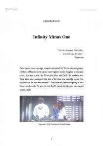
DEVS PROBLEM FORMULATION AND IMPLEMENTATION 2.1 Model of Spiking Neural Decoder Spiking neural networks are regarded as a next generation devices with significant advantage in speed over the traditional neural network devices [4]. In the present study DEVS formalism is employed in defining model of the neural spiking decoder, which function is to decode the incoming signal of spike sequences. The incoming messages are encoded in terms of time intervals between the initiating and terminating spikes, which here for simplicity of recognition are split into two parallel but separate channels. The general structure of the neural spiking decoder under consideration is shown in Fig.1.
5 msec 9 msec 3 msec
A B
A: ∆t= [1, 4] msec B: ∆t= [5, 8] msec C: ∆t= [9, 12] msec
C
{0;1} {0;1}
CBA
{0;1}
100 = A 010 = B 001 = C
Figure 1. Schematic of model of the neural spiking decoder. Alphabet is {A; B; C} with encoding rules listed via spike intervals. At the input there are three test combinations encoded in time intervals, at the output – the decoded sequence in terms of {0;1} triples. Neurons A, B and C are firing “1” in response to encoded by spikes intervals symbols “A”, “B” and “C”, or outputting “0” otherwise.
.
. .
Spiking Neural Decoder
Spiking Neuron A
A Controller-1
Timer-1
clk-1 Input #2
Pulses Transformer
signal
Out
Spiking Neuron B
B Controller-2
Timer-2
clk-2
reference Input #1
Spiking Neuron C Timer-3
C Controller-3
clk-3 [top] components : Transformer Neuron Neuron1 Neuron2 in : in_1 in_2 out : decoder_output control_output control1_output control2_output Link : in_1 in_1@Transformer Link : in_2 in_2@Transformer %%%%%%%%%%%%%%%%%%%%%%%%%%%%%%%%Neuron Link : out_1@Transformer neuron_on@Neuron Link : out_2@Transformer neuron_off@Neuron Link : neuron_out@Neuron decoder_output Link : clk_control@Neuron control_output %%%%%%%%%%%%%%%%%%%%%%%%%%%%%%%%Neuron1 Link : out_1@Transformer neuron1_on@Neuron1 Link : out_2@Transformer neuron1_off@Neuron1 Link : neuron1_out@Neuron1 decoder_output Link : clk1_control@Neuron1 control1_output %%%%%%%%%%%%%%%%%%%%%%%%%%%%%%%%Neuron2 Link : out_1@Transformer neuron2_on@Neuron2 Link : out_2@Transformer neuron2_off@Neuron2 Link : neuron2_out@Neuron2 decoder_output Link : clk2_control@Neuron2 control2_output
Figure 2. Schematic of the Simulator of Spiking Neural Decoder. The incoming message is the series of spikes, where symbols are encoded in terms of time intervals ∆t between odd and even spikes, where odd spikes initiate the time intervals of the symbol and even spikes terminate it. Ternary alphabet is used with symbols selected from the set {A; B; C}. As it is depicted in Fig.1, the encoding table of the alphabet symbols via ∆t intervals is as follows: 1 msec< ∆t < 4 msec for “A”, 5 msec< ∆t < 8 msec for “B”, and 9
. msec< ∆t < 12 msec for “C”. Spiking neurons A, B and C are responding to incoming symbol with output of 1 if the symbol is respectively “A”, “B” or “C”, while producing 0 as the output otherwise. In other words, neuron A is responding with output of 1 if incoming spikes are separated by ∆t as that for symbol “A” from the encoding table and with output of 0 otherwise (i.e. for symbols “B” and “C”).
Neurons B and C behave similarly, but for spikes with encoded symbols “B” and “C” respectively 2.2 Spiking Neural Decoder as top model The top model of Spiking Neural Decoder can be designed as shown in Fig.2. This design is relying on atomic and coupled models developed and tested in the model of Spiking Neural Terminal, described earlier [5]. Properties of the model of Spiking Neural Decoder differ from that of Spiking Neural Terminal of [5] in that in the Decoder the whole range of the time intervals is covered with three Neurons A, B and C connected in parallel (see Fig.1 and Fig 2) and therefore given legitimate symbol at the input the model has to provide response "1" at the output of the corresponding neuron (i.e. neuron A if input symbol is "A", neuron B if it is "B", and neuron C if it is "C") and output of "0" at the rest of neurons. Therefore the properties of the decoder's model can be formulated as a following set of rules, confirmation for which can be seen in the Table 7 (enumeration of the rules is connected to that of [5] in order to emphasize the fact that all these rules are related as the Decoder as the top model here is built from the atomic and coupled models of [5], where Spiking Neural Terminal was the last level of hierarchy; therefore the first rule number here is (xviii) as the next number after the last rule number in [5]): (xviii) for legitimate symbol inputs ("A", "B" and "C") there is always "1" at one firing output and "0" at the rest of firing outputs (where firing outputs are those comprising A, B and C outputs in Fig.1 and Fig.2); (xix) for each control output in SNT Simulator (variable control_output in Table) there are three consequtive control outputs of the same value ("1" or "-1") in the Decoder Simulator (outputs clk-1, clk-2 and clk-3 in Fig.2 and variables control_output, control1_output and control2_output in Table);
*
00:00:00:020 control_output 1
00:00:00:021 control_output -1
00:00:00:022 control_output 1
00:00:00:023 control_output -1
00:00:00:024 control_output 1
00:00:00:025 control_output -1
00:00:00:026 control_output 1
00:00:00:027 control_output -1
00:00:00:028 control_output 1
00:00:00:029 control_output -1 □ 00:00:00:029 terminal_output 0
00:00:00:032 control_output 1
00:00:00:033 control_output -1
Table. Comparative test of Spiking Neural Decoder and Spiking Neuron Terminal Simulators (rules xviii-xx). Output data for the Output data for the Spiking Neuron Spiking Neural Decoder Terminal Simulator Simulator 1 2 3 *
00:00:00:001 control_output 1 00:00:00:001 terminal_output 0
00:00:00:013 terminal_output 0
00:00:00:015 control_output 1
00:00:00:001 control_output 1 00:00:00:001 decoder_output 1 00:00:00:001 control1_output 1 00:00:00:001 decoder_output 0 00:00:00:001 control2_output 1 00:00:00:001 decoder_output 0 00:00:00:013 decoder_output 0 00:00:00:013 decoder_output 0 00:00:00:013 decoder_output 0 00:00:00:015 control_output 1 00:00:00:015 control1_output 1 00:00:00:015 control2_output 1
00:00:00:016 control_output -1 00:00:00:016 terminal_output 0
00:00:00:034 control_output 1
00:00:00:035 control_output -1
◊
00:00:00:036 control_output 1 00:00:00:036 terminal_output 1
00:00:00:039 control_output 1
00:00:00:040 control_output -1
00:00:00:041 control_output 1
00:00:00:016 control_output -1 00:00:00:016 decoder_output 1 00:00:00:016 control1_output -1 00:00:00:016 decoder_output 0 00:00:00:016 control2_output -1 00:00:00:016 decoder_output 0 00:00:00:020 control_output 1 00:00:00:020 control1_output 1 00:00:00:020 control2_output 1 00:00:00:021 control_output -1 00:00:00:021 control1_output -1 00:00:00:021 control2_output -1 00:00:00:022 control_output 1 00:00:00:022 control1_output 1 00:00:00:022 control2_output 1 00:00:00:023 control_output -1 00:00:00:023 control1_output -1 00:00:00:023 control2_output -1 00:00:00:024 control_output 1 00:00:00:024 control1_output 1 00:00:00:024 control2_output 1 00:00:00:025 control_output -1 00:00:00:025 control1_output -1 00:00:00:025 control2_output -1 00:00:00:026 control_output 1 00:00:00:026 control1_output 1 00:00:00:026 control2_output 1 00:00:00:027 control_output -1 00:00:00:027 control1_output -1 00:00:00:027 control2_output -1 00:00:00:028 control_output 1 00:00:00:028 control1_output 1 00:00:00:028 control2_output 1 00:00:00:029 control_output -1 00:00:00:029 decoder_output 0 00:00:00:029 control1_output -1 00:00:00:029 decoder_output 0 00:00:00:029 control2_output -1 00:00:00:029 decoder_output 1 00:00:00:032 control_output 1 00:00:00:032 control1_output 1 00:00:00:032 control2_output 1 00:00:00:033 control_output -1 00:00:00:033 control1_output -1 00:00:00:033 control2_output -1 00:00:00:034 control_output 1 00:00:00:034 control1_output 1 00:00:00:034 control2_output 1 00:00:00:035 control_output -1 00:00:00:035 control1_output -1 00:00:00:035 control2_output -1 00:00:00:036 control_output 1 00:00:00:036 decoder_output 0 00:00:00:036 control1_output 1 00:00:00:036 decoder_output 1 00:00:00:036 control2_output 1 00:00:00:036 decoder_output 0 00:00:00:039 control_output 1 00:00:00:039 control1_output 1 00:00:00:039 control2_output 1 00:00:00:040 control_output -1 00:00:00:040 control1_output -1 00:00:00:040 control2_output -1 00:00:00:041 control_output 1
00:00:00:042 control_output -1
00:00:00:043 control_output 1
00:00:00:044 control_output -1
00:00:00:045 control_output 1
◊
00:00:00:046 control_output -1 00:00:00:046 terminal_output 1
00:00:00:049 control_output 1
00:00:00:050 control_output -1
00:00:00:051 control_output 1
00:00:00:052 control_output -1
00:00:00:053 control_output 1
◊
00:00:00:054 control_output -1 00:00:00:054 terminal_output 1
00:00:00:041 control1_output 1 00:00:00:041 control2_output 1 00:00:00:042 control_output -1 00:00:00:042 control1_output -1 00:00:00:042 control2_output -1 00:00:00:043 control_output 1 00:00:00:043 control1_output 1 00:00:00:043 control2_output 1 00:00:00:044 control_output -1 00:00:00:044 control1_output -1 00:00:00:044 control2_output -1 00:00:00:045 control_output 1 00:00:00:045 control1_output 1 00:00:00:045 control2_output 1 00:00:00:046 control_output -1 00:00:00:046 decoder_output 0 00:00:00:046 control1_output -1 00:00:00:046 decoder_output 1 00:00:00:046 control2_output -1 00:00:00:046 decoder_output 0 00:00:00:049 control_output 1 00:00:00:049 control1_output 1 00:00:00:049 control2_output 1 00:00:00:050 control_output -1 00:00:00:050 control1_output -1 00:00:00:050 control2_output -1 00:00:00:051 control_output 1 00:00:00:051 control1_output 1 00:00:00:051 control2_output 1 00:00:00:052 control_output -1 00:00:00:052 control1_output -1 00:00:00:052 control2_output -1 00:00:00:053 control_output 1 00:00:00:053 control1_output 1 00:00:00:053 control2_output 1 00:00:00:054 control_output -1 00:00:00:054 decoder_output 0 00:00:00:054 control1_output -1 00:00:00:054 decoder_output 1 00:00:00:054 control2_output -1 00:00:00:054 decoder_output 0
1 2 3 (xx) for each firing output in SNT Simulator (variable terminal_output in the Table) there are three consequtive firing outputs in the Decoder Simulator (variable decoder_output in the Table); (xxi) for each "0" firing output in SNT Simulator (see marks "*" and "□" for terminal_output in the Table) there are three sequential outputs of either 1, 0, 0 or 0, 0, 1 (see those marked by respectively "*" for 100 and by "□" for 001 in the Table) at the Decoder Simulator firing output (output "Out" in Fig.2); (xxii) for each "1" firing output in SNT Simulator (see marks "◊" for terminal_output in the Table) there are three sequential outputs of 0, 1, 0 at the Decoder Simulator firing output (output "Out" in Fig.2 and variable decoder_output in the Table). It is seen from the Table, that the rules (xviii)-(xxii) are followed precisely. For instance, the rule (xviii) is always followed for all positions in the Table marked with either
"*", "□" or "◊". The rule (xix) is followed too as there are 3 control outputs in the Decoders column for each control output in the SNT column. Similarly, the rule (xx) is confirmed by the data of the Table, as there are 3 firing outputs in the Decoders column for each firing output in the SNT column. The rule (xxi) is verified by entries marked by "*" and "□", while the rule (xxii) by entries with "◊" marks in the Table. This concludes design, properties verification and validation of the top model of Spiking Neural Decoder Simulator, programmed in CD++ tool employing DEVS formalism approach. The model is validated at the level of its atomic components, coupled model components and top integrated hierarchical level. 3. CONCLUSIONS The following conclusions can be drawn form the above considerations. 1. CD++ toolkit is demonstrated as a suitable environment for simulation of the Spiking Neural Decoder, which is based on model of Spiking Neural Terminal (SNT) under DEVS formalism. 2. The model of Spiking Neural Decoder is built based on atomic and coupled sub-models involved as basic elements of reported earlier model of Spiking Neural Terminal. The expected properties of the Decoder’s model are formulated and are subjected to validation test, part of which stems from already validated rules for SNTs. Validation tests are conducted and the simulator of Spiking Neral Decoder is validated. 3. Hierarchy of the atomic models of amplifier, timer and controller, as well as coupled models of Pulses Transformer and Spiking Neuron comprising the coupled model of Spiking Neural Terminal are shown to support correct operation of the Decoder’s model. References: [1] Zeigler, B.P., The brain-machine disanalogy revisited, BioSystems, Vol. 64, pp. 127-140. (2002). [2] Michael Korkin1, Norberto Eiji Nawa, Hugo de Garis, A "Spike Interval Information Coding" Representation for ATR's CAM-Brain Machine (CBM) Volume 1478 (1998). [3] Obeid, I. Wolf, P.D, "Evaluation of spike-detection algorithms for a brain-machine interface application",Biomedical Engineering, IEEE Transactions on, Volume 51, Issue 6, page(s) 905- 911, June 2004. [4] R Mayrhofer, M Affenzeller, H Prahofer, G Hofer, A., “DEVS Simulation of Spiking Neural Networks”, Proceedings of Cybernetics and Systems (EMCSR), 2002. [5] Y. Boiko and G. Wainer, “Modeling Spiking Neural Terminals in DEVS”,- Proceedings of the 2008 Spring simulation multiconference, Spring SIM’2008 Poster Session, Article No. 19 in 2008 poster track, Ottawa 2008. [6] Y. Boiko and G. Wainer, “Modeling quantum dot devices in Cell-DEVS environment”,- ibid., Article No.18.