Wybrzeze Wyspianskiego 27. S-721 59, Vasterik, Sweden. 50-370 ..... Number 97TP120-0, Piscataway, NJ, USA 1997. M.M. Saha, K. Wikstrom,. J, Izykowski,.
New Concept
M.M. Senior
for Fault
Saha
Location
in Series-Compensated
J. Izykowski
K. Wikstrom
Member,
IEEE
Member,
Non-Member
New concept
for
fault
location
parallel
lines is presented. The developed
gorithm
offsets the series compensation
well as takes the countermeasure parallel
lines. Its distinctive
impedance minals
and for
Moreover,
the possible
complete
avoiding
The sample fault location satile ATP-EMTP
Keywords:
in series-compensated
one-end fault location
al-
and the reactance effects as coupling
between of the
systems behind both the line terlink
of pre-fault
between
the substations.
measurements
is provided.
cases for the fault data obtained
simulations
capacitor
50-370 Wroclaw,
for the mutual
extra
are included
compensated
transmission lines, digital recording, rithms, fault diagnosis, simulation.
mismatch
unreliable
ries-compensated
lines as the links between energy generation
and consumption
regions.
●
which are equipped with Metal-Oxide Varistors (MOVS) - for overvoltage protection. They make that measurement for such the lines differs substantially in comparison to the traditional lines - in both, the static and dynamic characters. parallel
power
lines with series compensation requires compensating for remote infeed effect under resistive faults, mutual coupling self. The fault location algorithm
●
of the remote
Thus, avoiding
of using pre-
only post-fault
measurements
acquired
at one end of par-
impedance data for the parallel lines has to be provided for the algorithm while impedances for equivalent sources behind the line terminals and for the possible extra link be-
simultaneous countermeasures are applied for the reactance effect, the series compensation effect and the mutual coupling between the lines,
●
the faults occurring in the remote system are discriminated, thus, the countermeasure for the mutual coupling between the lines is limited to the whole line length only,
●
effect it-
the computations are arranged in the phase coordinates allowing to represent the SCS and MOVS as the fundamental frequency equivalents and to locate faults in untransposed parallel lines too,
dedicated for parallel series-
compensated lines coping with all these the effects has been developed and presented in [4]. This was an extension of the algorithm developed earlier for a single series-compensated line [5, 6]. Both the methods are categorized as the one-end techniques. Their main drawback relies in requirement of the impedance data for the equivalent systems behind the line terminals and for the possible extra link between the substations. However, impedances of the equivalent systems can undergo fluctuations during evolving faults and impedance Possible for the remote system can not be mcmsured loGally,
features of the presented al-
summarize as follows:
tween the substations are not required to be known, ●
transmission
between the lines as well as for series compensation
value
allel lines is utiIized,
such the lines are con-
sidered as especially difficult for protective relaying as well as for locating faults for inspection and repair purposes [1-6]. This is due to Series Capacitors (SCS) installed in lines,
for
or even unavailable.
The advantages and distinctive
advantages, which are relevant for both, the par-
location
the representative
This paper presents entirely new concept for fault location in series-compensated parallel lines, which overcomes the aforementioned drawbacks of the previous method [4]. This is achieved by considering the healthy line path, in addition to the faulted line circuit, when deriving the subroutines of the fault location algorithm.
allel arrangement and for the series capacitor compensation [1], are the primary reasons for increased use of parallel se-
fault
between
Poland
fault quantities is also highly desirable.
gorithm
Accurate
IEEE
from ver-
and discussed.
transmission lines, coupled distance measurement, algo-
However,
Member,
system impedance provided for the location algorithm and its actual value causes additional errors in fault location. On the other hand, the previous one-end fault location algorithm [4] requires pre-fault measurements, which in some cases can be
I. INTRODUCTION
Combined
E. Rosolowski
Wroclaw University of Technology Wybrzeze Wyspianskiego 27
feature relies in no requirement
data for the equivalent
Lines
Senior
IEEE
ABB Automation Products AB Substation Automation Division S-721 59, Vasterik, Sweden
Abstract:
Parallel
●
the algorithm
is primarily
derived
for series-compensated
parallel lines but after adequate setting it is capable of locating faults in uncompensated parallel lines as well. The paper starts with
basics of the proposed
technique
(Section II), then in Section III the two specific subroutines of the fault location aIgorithm are derived. Examples of fault location with ATP-EMTP fault data follow (Section IV). Finally, the conclusions (Section V) close the paper.
0-7803-6674-3/00/$10.00 (C) 2000 IEEE
II. BASICS
OF THE FAULT
LOCATION
ALGORITHM
(Fig.la,
b). Equivalent
for different The presented algorithm proach [2, 3] for describing tive representing Arrangement
applies the phase coordinates parallel
SCs&MOVs
ap-
lines as well as for effec-
300 km parallel
rates (60, 70, 80 %) of 400 kV,
lines, taken for quantitative
analysis, are pre-
sented in Fig. 1c and d, respectively,
(Fig. 1) and a fault itself.
of series-compensated
parallel
lines as shown
in Fig.2, 3, where the models for two characteristic
The assumptions for deriving
the algorithm
The SCS with MOVS are represented in the algorithm by the impedance matrix dependent on amplitudes of currents:
spots of
faults are shown, is taken for the analysis, Both the lines are compensated with 3-phase banks of SCS equipped with MOVS installed at the distance p [pu] from the station A.
the algorithm
resistance and reactance, determined
compensation
are as follows:
is presented for neglected shunt capacitances
L&t)
=
Zy(pval)
o
0
o
Zv(pm)
o
o
0
Z“(p”’1)
I
1
(3)
where: Iv., I,b, 1.. are the currents flowing
through the banks in par-
of the lines, however, to improve the location accuracy for long lines the capacitances may be accounted for,
ticular phases and by I I the amplitude
the recorded voltage and current data cover the time window before firing the air-gaps (not shown in Fig. 1, 2, 3), which are in parallel with MOVS,
a)*”+=-b)
fault detection and classification is provided by a protective relay or by separate procedures of the fault locator, All the symbols stand for complex ances or phasors while
the matrix
is denoted.
4
numbers, either impedquantities
are bold-type c)
written. A. Parallel
lines model
Neglecting
the shunt capacitances the voltage drop across
the segment of the length x [pu] of the line A (Fig.2, 3) is determined with the matrix formula AVM
=X(ZUIM
[4]: (1)
+ZmI~B)
in which the self ( Z ~ ) and mutual
coupling
impedances could be, in general, of asymmetric ever, for completely
( Z ~ ) matrix form. How-
transposed parallel lines holds: “o
“ L%m-%m -Z(J
1%4.-zLA. %4.]
Self (s) and mutual (m) components
of Z ~
4000
2000 Amplitude
of Current
6000 Entering
8000 SC&MOV
(A)
d)
from (2) are
determined by the zero (0) and positive (1) sequence data: z ~,=
qzuo 3
+ %/t,),
Zom - mutual coupling B. Representation
Zu.
= $(ZMO
- AA,)
,
-------- .-. ,
zero sequence impedance.
of SCs and MOVS 80%
A bank of parallel branches of a SC and its MOV
is repre-
sented for the thndamental frequency phasors by equivalent resistance and reactance, connected in series. The equivalencing technique, based on using ATP-EMTP simulations [4-7], assumes that the fundamental frequency phasors in the original arrangement and in the series equivalent match
-801 o
J 2000
Amplitude
4000
of Current
6000 Entering
8000 SC&MOV
(A)
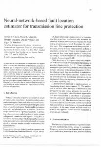
Fig, 1. Equivalencing of SC&MOV for different compensation rates: a) the original scheme, b) the tirndamental frequency equivalent circuit, c) the equivalent
0-7803-6674-3/00/$10.00 (C) 2000 IEEE
resistance, d) the equivalent
reactance.
.
C. Fault model A general fault model introduced fault location algorithm.
in [4-6] is utilized
Subroutine SCs&MOVs
in the
(X2 [pu]) satisfies:
It is stated in matrix notation as:
Xj p,
–Zvfl
IM U)IM –(Z.
–ZL~ –Zvfl
‘z
EQ ..................z. I AB
%A
Pz
%
LB
~~~