NEW METHOD FOR COMPUTING TRANSMISSION COEFFICIENT OF INTEGRATED FERRITE COPLANAR ISOLATOR D. Vincent1, C. R. Simovski2 , B. Bayard1, G. Noyel1 1- DIOM, Devices and Instrumentation in Optics and Microwaves, Université Jean Monnet , 23 rue Paul Michelon 42023 Saint-Etienne cedex France. Tel : 00 33 4 77 48 50 18 Fax : 00 33 4 77 48 50 39 Email :
[email protected] 2- Physics Department, St Petersburg State Institute for Fine Mechanics and Optics, Sablinskaya 14, 197101 St- Petersburg Russia. ABSTRACT The transmission coefficients of a non-reciprocal coplanar waveguide using ferrite rods is computed. A new approximate method is proposed to evaluate the direct and reverse propagation constant of such a perturbed waveguide. The propagation constant of the non-perturbed waveguide or coplanar line is calculated using the Spectral Domain Approach method. From these numerical data we have estimated the value of the nonreciprocity effect and settled the condition of the validity of our theory. The first experimental data are presented when ferrofluids or magnetic powders are deposited on the coplanar waveguide. INTRODUCTION Some non reciprocal microwave components such as isolators and circulators are based on the gyromagnetic properties of ferrites. The ferrite bulk substrate is magnetized by a constant magnetic field which makes this kind of devices non MMIC compatible and only available in discrete packages. On the other hand, the active components which are completely integrated show a higher noise level, insertion losses and a lower frequency range (about 5 GHz) than the passive devices. At the DIOM Laboratory, research activities are made to design non-reciprocal passive components on chips. A coplanar ferrite isolator is adopted since it is built with coplanar strips on a dielectric substrate and it needs only a small quantity of ferrite material in the slots. Long ago C. P. Wen (1) made a non-reciprocal isolator using two ferrite rods placed at the dielectric interface between strips (figure 1). The physical foundation of this isolator is based on the different h vector rotations for forward and backward propagation. The magnetic force line is not closed inside the ferrite sample and the transversal distribution of the microwave magnetic field h is assumed to be practically uniform for the frequency bands and rod sizes used. When the applied magnetic field direction is horizontal (along the y axis in figure 1) the plane of the spin precession excited by a microwave magnetic field is the vertical (xz) plane. If the h vector, at a given point of the rod, rotates in the same direction as the inner magnetisation vector m, the wave energy is absorbed by the spins. In the opposite case there is no spin-wave interaction. Therefore, the physical foundation of the isolator studied in (1) is based on the different h vector rotations for forward and backward propagation. PROPAGATION COEFFICIENTS COMPUTING The Spectral Domain Approach method (2), (3) is used to calculate electric and magnetic field components between the strips of an unperturbed coplanar waveguide. The h field polarization is elliptical at the interface. Consider the h vector when the mutual coupling of the ferrite rods is negligible. At first, we give the theoretical explanation of the operation of reference isolator (figure 1), then we evaluate the propagation factors and calculate the transmission coefficients. Let a single ferrite rod be centered at the arbitrary point of the waveguide cross section. The field h0 applied to this rod is the field taken at the same point of an unperturbed CPW. Assuming h0 is known over the ferrite rod cross section (assumed to be very small compared to the wavelength) we may write the well known magnetostatic relation for internal field h generated in the rod by external field h0 :
(
)
h0 = I + N χ h
(1)
Here N and χ are respectively the demagnetizing tensor (dyadic) and the susceptibility tensor (dyadic). The demagnetizing and susceptibility tensors are getting complex values at the resonance band. The rod is extended along the z axis, so we can set Nz ≈ 0, hz = h0z and we have : h0 x + jκN x h0 z hx = hz (2) 1 + χN x when the ellipticity factor
h0 x = jξ is a complex number depending on frequency. It is however, a small h0 z
value, and the polarization is close to a linear one. At low frequencies (the transversal size of CPW is small compared to λ ) h0x has almost the same phase as that of the longitudinal currents in the strips and h0z ‘s phase is close to that of the displacement current between them. Therefore the phase shift between these components is close to π/2 radian and jξ is almost purely imaginary. Assuming real parts of χ and κ are close to 0 at the resonance frequency, the ratio hx/hz is given by : hx jξ + κ ′′N x (3) ≈ h z 1 − jχ ′′N x When the demagnetizing factor Nx vanishes we have of course h = h0. When χ ′, κ ′ are negligible and N x κ ′′ ≈ χ ′′N x (the values at the resonance are large compared to ξ ) the polarization of the internal magnetic field in the rods becomes almost circular hx ≈ jhz (even if ξ is small). With this assumption, we calculate the microwave internal magnetisation m = χ h , and find : mx m = − j if the applied magnetic field is directed along y axis and x = j in the reverse direction (for the mz mz reverse direction, κ must be replaced by -κ). When the next ratio is j, both the magnetic field and the magnetic moments rotate in the same direction, and the energy of the propagating wave is absorbed. Otherwise, spin-wave interaction is very weak. This case corresponds to the optimal operation of the isolator. Now we propose a new approximate method for evaluating the propagation constant. This method is applied for the cases of ferrite rods whose transversal size is small in comparison to the wavelength. Let the mode with propagation constant jβ propagate in the perturbed waveguide. Then : e(x, y, z ) = E(x, y )e − jβz , h(x, y, z ) = H(x, y )e − jβz , m(x, y, z ) = m(x, y )e − jβz where e, h, m are respectively microwave electric, magnetic and bulk magnetisation fields. From Maxell ‘s equation : ∂E z + jβE y = − jω (1 + χ )H x − ωµ 0κH z (4) ∂y Without ferrite rod this relation is : ∂E 0 z (5) + jβ 0 E 0 y = − jωµ 0 H 0 x ∂y If the ferrite permittivity is close to the dielectric matrix one and the frequency is low, the transversal distribution of the electric field is slowly perturbed by the ferrite rod insertion and we can allow : ∇ y E z ≈ ∇ y E 0 z and E y ≈ E 0 y (6) If we only do these rough approximations, relation (4) becomes : ∂E 0 z (7) + jβE 0 y = − jωµ 0 (1 + χ )H x − ωµ 0κH z ∂y The internal magnetic field (inside the ferrite rods) is obtained from demagnetizing factor Nx (relation (2)). Using the SDA method all field components can be calculated and after substitution we find a very simple relation: H β ± = β 0 ± jωµ 0ψ (κ − ξχ ) 0 z (8) E0 y
ψ =
h 1− Nx and 0 x = jξ , χ and κ are susceptibility dyadic components, H 0 z and E 0 y are h0 z 1 + χN x
respectively the magnetic field component along the z axis and the electric field component along the y axis for the unperturbed coplanar waveguide. Finally to take each point in the rods into account we average relation (8) over the interface length L, considering the thickness of the rods as negligible (it implies the only integration on the y axis), and we obtain : L H 2 ± jωµ 0ψ (κ − ξχ ) 0 z dy (10) β = β0 ± L0 E0 y
∫
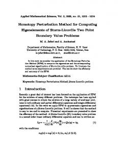
RESULTS Numerical results which have been computed using the following values are shown in figure 2: α = 0.1, , M s = 140 kA / m, γ = 2π .28.10 9 , (ε r = 11 − j 0.1), H 0 = 200 kAm -1 and 300 kAm -1 To calculate χ and κ the Polder tensor model is chosen (4). Significant non reciprocal transmission magnitude has been predicted in the CPW with magnetised ferrite rods. This effect increases with the ferrite magnetisation. Experimental results are shown in figure 3. A Mag-Hematite ferrite powder has been placed at the interfaces of a CPW and the scattering parameters S21 and S12 were measured with a HP 8510 network analyser in the frequency band 2-20 GHz. The ferrite powder was made from nano-particles ( mean diameter 10 nm) of Mag-Hematite. The physical meaning of the curves in figures 2 and 3 is the same. However, it is not possible to compare exactly theoretical and experimental curves because at the present time we still do not have an exact electromagnetic model for the tensor permeability of this granular material. However, the qualitative agreement between calculated and experimental curves is visible from comparing the corresponding curves in figures 2 and 3. The same non reciprocal phenomenon occurs and increases with the applied magnetic field in our theory as well as in our measurements .
CONCLUSION A simple and explicit method of evaluating the propagation constants and transmission losses of a nonreciprocal coplanar isolator is presented. From the data obtained by the Spectral Domain Approach method for the unperturbed coplanar waveguide we calculate the propagation constants for the forward and backward propagation directions of the isolator (a perturbed coplanar waveguide). Non reciprocal transmission in our theoretical model turns out be significant as well as in our experimental results.. Although some rough approximations have been done in our model, the experimental and theoretical curves are in qualitative agreement. The approximate theory presented above can be improved by taking into account the coupling between ferrite rods. REFERENCES (1) Chen P. Wen, « Coplanar Waveguide : A Surface Strip Transmission Line Suitable for Nonreciprocal Gyromagnetic Device Applications », IEEE Trans. Microwave Theory Tech., Vol. MTT-17, n°12, 1087-1090, December (1969). (2) T. Itoh, R. Mittra, « Spectral Domain Approach for calculating the Dispersion Characteristic of Microstrip Lines »,IEEE Trans. Microwave Theory Tech., Vol. MTT, n°21, July (1973) 496499. (3) (3) T. Itoh, « Spectral Domain Immitance Approach for Dispersion Characteristic of Generalized Printed Lines »,IEEE Trans. Microwave Theory Tech., Vol. MTT, n°28, July (1980) 733736. (4) B. Lax, K. J. Button, « Microwave ferrites and ferromagnetics », NY, McGraw Hill (1962).
FIGURES
Field vector h rotation
Field vector h rotation x z
y
B0
Ferrite rods Substrate
B0 Ferrite rods Magnetic moments Substrate rotation in both rods
Magnetic moments rotation in both rods
Figure 1 : Coplanar waveguide with ferrite rods. The physical foundation of the isolator is based on the different h vector rotations and spin wave interaction for forward and backward propagation. 2
0
-2 lo s s e s in d B
-4 fo rw a rd b a c k w a rd d if f e r e n c e
-6
-8 A p p lie d f ie ld H o : 2 0 0 k A / m
-1 0
A p p lie d f ie ld H o : 3 0 0 k A / m
-1 2 -2
0
2
4
6
8 10 F re q u e n c y G H z
12
14
16
18
Figure 2 : Simulation results. The Polder model of the magnetic material is chosen with the damping factor α = 0.1 , magnetisation M s = 140 kA / m, and permittivity ε r = 11 − j 0.1 0 S 21= S 12
-2
Bo = 0 mT
Transmissions (dB)
-4
-6
-8
S 21
-1 0 B o = 430 m T
∆S
S 12
-1 2
-1 4 0
5
10
f
r
15
F re q u e n c y (G H z )
20
Figure 3 : Experimental results with Mag-Hematite powder placed between the coplanar waveguide strips