New Parallel Algorithm For Mitigating The Frequency Offset of OFDM Systems Hen-Geul Yeh Electrical Engineering Department California State University, Long Beach Long Beach, CA 90840-8303 E-mail:
[email protected]
Charles C. Wang The Aerospace Corp. 2350 E. El Segundo El Segundo, CA 90245-4691 E-mail:
[email protected]
Abstract– In this paper we study the problem of frequency offset due to the Doppler velocity of orthogonal frequency division multiplexing (OFDM) systems. A regular OFDM has an IFFT at the transmitter and an FFT at the receiver. The proposed parallel algorithm employs an FFT at the transmitter and an IFFT at the receiver. The regular OFDM samples, which generated by the IFFT, are transmitted as the 1st block, and the FFT outputs are transmitted as the 2nd block. At the receiver, results of the 1st output generated by the FFT, are combined with the 2nd output generated by the IFFT. This combined operation forms a parallel intercarrier interference (ICI) cancellation scheme for mitigating frequency offsets of OFDM systems. It provides (1) a robust OFDM system in the presence of relative velocity, also known as Doppler frequency offset; (2) high signal to ICI ratio (7 dB better than that of the linear self-cancellation algorithms at N=1024 and ∆fT ≤ 1% of subcarrier frequency spacing); (3) backward compatibility with the existing OFDM system; (4) better BER performance in both additive white Gaussian noise (AWGN) and fading channels. I.
INTRODUCTION
Multi-carrier modulations, in particular, orthogonal frequency division multiplexing (OFDM), have enjoyed popularity in the past several years. Due to its advantages of improving bandwidth efficiency and data throughput over the mobile radio channel, OFDM has been used in many new digital wireless applications. Unfortunately, one of the major disadvantages of an OFDM system is the sensitivity of its performance to a frequency offset. Such a frequency offset causes a loss of subcarriers’ orthogonality, and intercarrier interference (ICI) occurs. In order to maintain the orthogonality and have no crosstalk among subcarriers at the OFDM receiver, two conditions must be satisfied: (1) the demodulating subcarriers need to be exactly aligned with the transmitted subcarriers; and (2) T must be
0-7803-8521-7/04/$20.00 © 2004 IEEE
exactly equal to the reciprocal of the subcarrier frequency spacing. If one of these conditions is not met, the orthogonality is no longer maintained and the ICI, or, crosstalk, is self-generated among these subcarriers at the receiver. Currently, three different approaches for mitigating ICI have been proposed including: ICI self-cancellation [1-2], frequency-domain equalization [3], and time-domain windowing scheme [4]. Frequency offset estimation techniques using training sequence such as pilot symbols are proposed in [5-6]. This study focuses on the ICI cancellation scheme and its effect on OFDM communication systems in AWGN and fading channels, assuming that the synchronization, including phase, frequency, and timing has done by using repeated preamble sequence, but the ICI may still exist due to the frequency offset estimation error or unexpected Doppler velocity. This paper is organized as follows. The OFDM system in additive white Gaussian noise (AWGN) channel is discussed in Section II. The math model of the transmitter and the receiver are described in Section III, along with a discussion of the weighting function of the data symbol due to frequency offset. Section IV presents a parallel algorithm, the parallel cancellation (PC) system and the corresponding architecture of the transceiver. Simulation results are discussed in Section V. Conclusions are given in Section VI. II. OFDM SYSTEMS The Fast Fourier Transform (FFT) is the most effective way to realize the orthogonal frequency modulation. The OFDM system can be depicted as in Figs 1a and 1b. In the transmitter side, the serial-toparallel (S/P) operation essentially performs the grouping of N consecutive data symbols into N parallel inputs to the Inverse FFT (IFFT). Note that the IFFT has TOFDM seconds to complete its operation. The duration TOFDM for an OFDM symbol is N·Ts, where Ts is the data symbol time duration. For simplicity, T is used to replace TOFDM in the following discussion. After
2087
0-7803-8521-7/04/$20.00 (C) 2004 IEEE
the IFFT, the N-point IFFT outputs are put into a serial stream by a Parallel-to-Serial (P/S) operation. The time spacing between each output sample is Ts. Finally, this sequence is transmitted via a digital-to-analog converter (D/A) and a carrier, which is omitted in Fig. 1. All the reverse operations take place on the receiver side.
1 dˆ n = N
N −1
∑ rk e
−j
2π nk N
(2)
k =0
rk = x k e
where
n = 0,1,2,..., N − 1
j
2π k∆fT N
+ wk .
rk
represents the
received signal at the input to the FFT processor, wk is the AWGN, and dˆ n is the output of the FFT processor.
Modulation . . (BPSK, dn . S/P QPSK, 16QAM, 64QAN)
. N Point . . Inverse FFT
j
P/S
Note that e , k = 0,1, ... , N − 1 , represent the corresponding residue carrier frequency error of the received signal at the sampling instants due to the synchronization error. The carrier phase has been estimated and compensated by using the repeated preamble sequences in the carrier requisition process. For simplicity, the phase is not shown in the received signal. Without loss of generality, the noise wk is assumed to be zero in the following discussion.
xk
Fig. 1(a). Simplified transmitter block diagram.
rk
S/P
. . .
. . N Point . FFT
P/S
Demodulation
dˆn
C. The Complex Weighting Factor Following the similar derivation in [2], the ICI resulting from the carrier frequency offset is analyzed. Substituting (1) into (2) and after some manipulation, it can be shown that
Fig. 1(b). Simplified receiver block diagram. II.
1 dˆ n = N
SYSTEM MODEL
A. Regular OFDM Transmitter A conventional OFDM modulation is employed at the transmitter. The baseband transmitted signal xk at the output of the IFFT can be written as N −1
x k =∑ d n e
j
2π nk N
k = 0,1,2,..., N − 1
e
j
2π nk N
dn
N −1
N −1
l =0
k =0
∑ dl ∑ e
j
2πk ( l − n + ∆fT ) N
n = 0,1,2,..., N − 1
(3)
Taking the advantage of the properties of geometric series, this can be derived as
1 dˆ n = N
N −1
1 − e j 2π (l − n + ∆fT )
l =0
1− e
∑ dl
j
(4)
2π ( l − n + ∆fT ) N
N −1
= ∑ d l ul −n
(1)
n = 0,1,2,..., N − 1
l =0
n =0
where
2π k∆fT N
where is
the
data
symbol,
and
ul −n =
, k = 0,1, ... , N − 1 , represent the corresponding
orthogonal frequencies of N subcarriers. B. Regular Receiver Baseband Processing At the receiver, the signal is mixed with a local oscillator signal, which is ∆f above the correct carrier frequency. After the carrier frequency removed, the baseband demodulator processing (FFT) is given by
1 1 − e j 2π (l −n + ∆fT ) 2π j ( l − n + ∆fT ) N 1− e N
Clearly, the complex weighting factors u 0 , u1 , ..., u N −1 indicate the contribution of each of the N data symbols
d l to the FFT output dˆ n . Note that the weighting factor is a periodic function with a period equal to N. If the normalized frequency offset ∆fT equals zero, the
dˆ n is exactly equal to d n . With some manipulation, equation (5) can be rewritten as
0-7803-8521-7/04/$20.00 © 2004 IEEE
(5)
2088
0-7803-8521-7/04/$20.00 (C) 2004 IEEE
u l − n =e
j
Equation j
π
π N
( N −1)( l − n + ∆fT )
(6)
1 sin(π (l − n + ∆fT )) (6) π N sin( (l − n + ∆fT )) N
consists
of
the
rotation
factor
( N −1)( l − n + ∆fT )
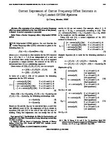
e N and the Dirichlet function 1 sin(π (l − n + ∆fT )) . The Dirichlet function of N sin(π (l − n + ∆fT ) / N ) (6) is plotted in Fig. 2 as a continuous function of the normalized frequency at N=8, n=0 with ∆fT =0 and ∆fT =0.2, respectively. The discrete weighting factors
u 0 , u1 , ..., u 7 of 8 symbols are located exactly at the 0, 1, 2, … , 7 integer-point of the frequency axis regardless ∆fT . At ∆fT =0, all weighting factors are zeros except that the real part of u 0 equals one. This is because it holds the orthogonality and has no crosstalk among subcarriers at the receiver. However, the curve of the Dirichlet function of Fig. 2 shifts to the left by ∆fT when the frequency offset ∆fT >0. Such a frequency offset causes a loss of the subcarriers’ orthogonality, and hence all weights on data symbols are non-zero valued and ICI is self-introduced, as depicted in Fig. 2. 1
Dirichlet function of regular OFDM at n=0
0.8
freq offset = 0.2
changes the weighting factors of data symbols from zero to positive or negative values at integer frequency points, as shown in Fig. 2. The new approach in this paper is to develop an additional parallel algorithm such that the curves of the Dirichlet function of Fig. 2 shift to the right (instead of left) by ∆fT when the frequency offset ∆fT is greater than zero. This shift-to-right operation changes the weighting factors from zero to negative or positive values in the reversed direction of that of the shift-to-left operation. The combined weighting factors (the regular and the parallel algorithms) will provide a significantly smaller weighting function on undesired data symbols while maintaining the same weighting function on the desired data symbol as that of the regular OFDM system. Consequently, this new set of algorithms improves the signal-to-ICI ratio and effectively mitigates the ICI problem. The parallel algorithm requires an FFT operation at the transmitter as defined in (7): 2π N −1 (7) −j nk
x k' = ∑ d n e n =0
where
e
−j
2π nk N
dn
is
dˆ n' =
data
symbol,
and
, k = 0,1, ... , N − 1 , represent the corresponding
∑r e N ' k
n = 0,1,2,..., N − 1
N
k =0
0.4
where rk' = x k' e
0.2
j
2π k∆fT N
+ wk' represents the received
signal at the input to the IFFT processor, wk' is the
0
' independent AWGN, and dˆ n is the output of the IFFT
-0.2 -0.4
j
-0.6 -0.8 -1 0
the
orthogonal frequencies of N subcarriers. This parallel algorithm also requires an IFFT operation at the receiver as defined in (8): 2π (8) 1 N −1 j nk
freq offset = 0
0.6
k = 0,1,2,..., N − 1
N
1
2
3 4 5 Normalized Frequency index
6
7
Fig. 2. The Dirichlet function. III. PARALLEL ALGORITHM The Dirichlet function of (6) has zero-crossing points that are evenly spaced in the frequency domain (i.e., the FFT output). The curve of the Dirichlet function of Fig. 2 shift to the left by ∆fT when the frequency offset ∆fT is greater than zero. This shift-left operation
0-7803-8521-7/04/$20.00 © 2004 IEEE
2π
k∆fT
processor. Note that the e N , k = 0,1, ... , N − 1 , represent the corresponding frequency offset of the received signal at the sampling instants. Note that the carrier phase has been estimated and compensated by using the repeated preamble sequences in the carrier requisition process. For simplicity, the phase is not shown in the received signal. Without loss of ' generality, the noise wk is assumed to be zero in the following discussion. Substituting (7) into (8) with frequency offset and after some manipulation, it can be shown that
2089
0-7803-8521-7/04/$20.00 (C) 2004 IEEE
N −1
N −1
l =0
k =0
∑ dl ∑ e
j
2πk ( n − l + ∆fT ) N
n = 0,1,2,..., N − 1.
(9)
By following a similar derivation as that of Section III, one obtains the following weighting factors for the parallel IFFT output:
v n − l =e
j
π N
( N −1)( n − l + ∆fT )
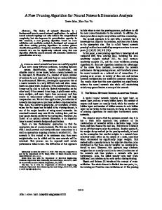
in Fig. 5 at N=16 in AWGN channel. The BER curve of the regular OFDM system becomes flat at ∆fT = 0.06 with large Eb/No. On the other hands, the BER curve of the PC system has a waterfall shape at ∆fT = 0.06 . At ∆fT = 0.04 , it also has a 4 dB advantage over the regular OFDM system at BER=0.0001.
1 sin(π (n − l + ∆fT )) (10) π N sin( (n − l + ∆fT )) N
70
Equation (10) is similar to (6), but the sign of n and l are swapped. Assuming both a regular OFDM algorithm and a parallel algorithm can be combined coherently without interfering each other by using a division multiplexing technique, such as frequency division multiplexing (FDM), or time division multiplexing (TDM), or code division multiplexing (CDM), the final detected symbol is then chosen as follows: 1 (11) dˆ n" = (dˆ n + dˆ n' ) n = 0,1,2,..., N − 1 . 2
60
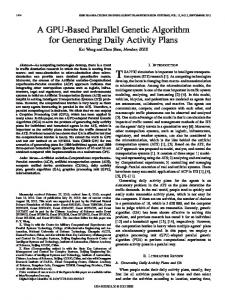
N=1024
50
N=128 N=64
SICIR (dB)
1 dˆ n' = N
40
N=32
30
N=16 N=8
20 10 0 -100
Regular OFDM
0.1
0.2
0.3 0.4 0.5 0.6 0.7 0.8 0.9 Normalized frequency offset index
Figure 3. Signal to ICI ratio.
The signal to ICI ratio of this PC scheme is depicted in Fig. 3 as a function of frequency offset and the number of subcarriers. The higher N, the better SICIR the PC scheme has.
Modulation . N-Point . (BPSK, . IFFT(1st) . dn . P/S QPSK, S/P . and 16QAM, FFT(2nd) 64QAN)
A single antenna architecture for the transmitter and receiver is described in Figs. 4(a) and (b), respectively. A CDM, TMD, or FDM is required at the transmitter to make parallel transmission. A de-multiplexing circuit is required at the receiver in order to perform parallel receiving operations accordingly. An equal gain combiner is applied to combat the fading noise [7].
xk
Fig. 4(a). The parallel transmitter. 1st branch
IV. SIMULATION RESULTS
The signal processing for the transmitter and receiver described in Figs. 4(a) and 4(b), respectively, was simulated in AWGN and frequency selective 3-ray Rummler fading channels. For fair comparison, each branch at the transmitter of the PC system is at half of the original signal power of the regular OFDM system in all simulations. Note that BER performance of both the regular 16-QAM OFDM and the PC system with frequency offsets from ∆fT = 0.04 to 0.06 is provided
0-7803-8521-7/04/$20.00 © 2004 IEEE
1
rk
. N-Point . . . . FFT(1st) . S/P P/S and IFFT(2nd)
Demod
Diversity Combiner
2nd branch
Fig. 4(b). The parallel receiver.
2090
0-7803-8521-7/04/$20.00 (C) 2004 IEEE
dˆn
V. CONCLUSIONS
1.E+00
Theo-0.00 Reg-0.04 PC-0.04 Reg-0.06 PC-0.06
BER of 16QAM OFDM
1.E-01 1.E-02
By using the PC scheme, the sensitivity of the OFDM system to ICI is reduced. The key feature of this new scheme is that it provides a higher SICIR at a higher N in the presence of frequency offsets. When N=16, this new scheme improves the maximum tolerable frequency offset from 4% of a conventional OFDM system to 6% of the subcarrier frequency spacing in AWGN channel. This PC scheme also provides better BER performance for a wide range of frequency offset over a regular OFDM system in 3-ray Rummler fading channels. Although the bandwidth efficiency is reduced to half due to twice transmission, it can be compensated by using larger signal alphabet sizes.
1.E-03 1.E-04 1.E-05 1.E-06 0
4
8
12 16 Eb/No dB
20
24
28
REFERENCES
Fig. 5. BER performance in AWGN channel. A 3-ray Rummler fading model [8] with frequency offset is employed. A 25% guard time is applied to the DQPSK OFDM signal with N=1024. Frequencydomain differential coding is applied in both systems in order to avoid channel response estimation. The data rate is 20 Mbps. This channel model is composed of three propagation paths: a line-of-sight (LOS) path, and two specular reflections (2nd and 3rd rays) with Rayleigh distribution. The 2nd ray has a signal strength that is 83% of that in the LOS path with a delay of 50 ns. The amplitude of the 3rd ray is 2% of that of the LOS ray with a 150 ns delay. The BER is depicted in Fig. 6. 1.E+00
Reg-0.01 PC-0.01 Reg-0.04
BER of DQPSK OFDM
1.E-01
PC-0.04 Reg-0.1
1.E-02
PC-0.1
1.E-03
1.E-04
1.E-05 4
8
12
16
20
24
28
32
Eb/No (dB)
Fig. 6. BER performance in fading channel.
0-7803-8521-7/04/$20.00 © 2004 IEEE
36
40
[1] Y. Zhao and S-G. Haggman, “Intercarrier interference self-cancellation scheme for OFDM mobile communication systems,” IEEE Trans. Commun., vol. 49, no. 7, pp. 1185-1191, July 2001. [2] J. Armstrong, “Analysis of new and existing methods of reducing intercarrier interference due to carrier frequency offset in OFDM,” IEEE Trans. Commun., vol. 47, no. 3, March 1999, pp. 365-369. [3] N. A. Dhahi et al., “Optimum finite-length equalization for multicarrier transceivers,” IEEE Trans. Commun., vol. 44, no. 1, pp. 56-64, Jan. 1996. [4] C. Muschallik, “Improving an OFDM reception using an adaptive Nyquist windowing,” IEEE Trans. Consumer Electron., vol. 42, pp. 259-269, Aug. 1996. [5] P. H. Moose, “A technique for orthogonal frequency division multiplexing frequency offset correction,” IEEE Trans. Commun., vol. 42, no. 10, Oct. 1994, pp. 2908-2914. [6] T. M. Schmidl and D. C. Cox, “Robust frequency and timing synchronization for OFDM,” IEEE Trans. Commun., vol. 45, no. 12, pp1613-1621, Dec. 1997. [7] T. Eng, N. Kong, and L. B. Milstein, “Comparison of diversity combining techniques for Rayleighfading channels,” IEEE Trans Commun., vol. 44, pp. 1117-1129, Sept. 1996. [8] M. Rice, A. Davis, C. Bettweiser, “A wideband channel model for aeronautical telemetry,” IEEE Trans. Aerospace and Electronics Systems, vol. 40, pp. 57-69, Jan. 2004.
2091
0-7803-8521-7/04/$20.00 (C) 2004 IEEE