MATEC Web of Conferences 233, 00017 (2018) https://doi.org/10.1051/matecconf/201823300017 EASN-CEAS 2018
New prognostic neural method by discrete wavelet transforms for electromechanical flight controls affected by progressive faults Matteo D. L. Dalla Vedova1,*, Nicola Lampariello1 , and Paolo Maggiore1 1Department
of Mechanical and Aerospace Engineering (DIMEAS), Politecnico di Torino Corso Duca degli Abruzzi, 24 - 10129 - Torino, ITALY Abstract. Progressive failures affecting onboard electromechanical actuators (EMA), especially if related to primary flight commands, could be a critical issue for the aircraft reliability and, in the worst cases, could compromise its safety. In the last years strong interest is expected by the development of prognostic algorithms able to provide an early identification of the precursors of EMA progressive failures. In this work authors proposes a new prognostic method based on two artificial neural networks (ANN), a basic and an enhanced feedforward neural network, performing the fault detection and identification of two critical progressive faults often affecting the EMA brushless motor (i.e. turn-to-turn short circuit of a stator coil and rotor static eccentricity); in order to identify a suitable data set able to guarantee an affordable ANN classification, the said failures precursors are properly pre-processed by a Discrete Wavelet Transform, extracting several features used as input of the proposed prognostic algorithm.
1 Introduction In the recent decades, the electromechanical actuator (EMA) is playing an increasingly important role as an augmented flight control system in fly-by-wire architectures. In this scenario, studies in prognostics will be necessary to reduce maintenance costs and preserve safety because, otherwise from mechanical fatigue, which can be estimated with a reliable confidence level, EMA electrical failures, like a partial stator phase short-circuit or rotor eccentricity, are difficult to predict using an external analysis. The causes of these failures, such as current peaks or stresses, are often unpredictable and the effects are undetectable in large scale. For example, if an initial incipient damage occurs, system performance and response could remain almost constant, while the fault could rapidly degenerate into a critical damage which compromises the system correct working, causing the actuator failure. The main objective of the Prognostics and Health Management (PHM) is the ability to analyse the behaviour of components to determine their degradation pattern (as reported by Vachtsevanos et al. [1], Brown & Vachtsevanos [2], Byington et al. [3]).
*
Corresponding author:
[email protected]
© The Authors, published by EDP Sciences. This is an open access article distributed under the terms of the Creative Commons Attribution License 4.0 (http://creativecommons.org/licenses/by/4.0/).
MATEC Web of Conferences 233, 231, 00017 (2018) https://doi.org/10.1051/matecconf/201823300017 (2018) https://doi.org/10.1051/matecconf/201823100017 GAMBIT 2018 EASN-CEAS 2018
It must be noticed that commonly, in aeronautical applications, many components have limited life duration even if limited life is considered to be abundant with respect to the maintenance interval (safe life approach), work out of design and unmonitored loads can produce a reduction of this design duration. Then, the system functionalities can degrade rapidly, causing safety issues. The PHM goal is to provide real-time data about the current status of the system and to predict the Remaining Useful Life (RUL) (Vachtsevanos et al. 2006) before a fault occurs. The main advantages brought by PHM strategies are obvious when their results are compared with those obtained with classical monitoring and maintenance philosophy (e.g. based on overhaul or life-limited parts). The safe life approach does not involve the evaluation of the real status of the components and maintenance operations are scheduled; moreover, this approach is not able to consider any initial flaws which could degenerate in a catastrophic fault that compromises the aircraft safety. Proper PHM strategies could handle progressive failures in a more effective way leading to a substantial reduction of system redundancies, operating costs, maintenance interventions and, on the other hand, improving the aircraft safety and reliability plus simplifying logistics (as reported in [2]). To these purposes, in this paper is proposed be the authors a new Fault Detection and Identification (FDI) technique [3], based on Artificial Neural Networks (ANNs), able to identify the failure precursors and predict the corresponding damage entity. In order to identify a suitable data set able to guarantee an affordable ANN classification, Discrete Wavelet Transform is used to properly process the said failures precursors extracting several useful features: in fact, these time-frequency analysis result very effective to detect fault condition by means of the change in amplitude and shape of its coefficients.
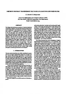
Fig. 1. Electromechanical actuator (EMA) scheme.
The algorithm effectiveness has been evaluated by a dedicated MATLAB-Simulink® numerical model, able to analyse the EMA performance and the responses of two progressive faults; the so obtained results demonstrate the robustness of the method and the ability to identify the incoming failures, reducing the possibility of false alarms rather than non-predicted problems.
2 Primary flight control EMA Until a few years ago, the actuators mainly used in aeronautic are generally hydraulic and precisely hydromechanical and, only more recently, electrohydraulic. This kind of actuator has great accuracy, high specific power and very high reliability; it is often equipped on current aircrafts, even if on more modern airliners electro-hydrostatic actuators (EHA) or electro-mechanical actuators (EMA) are installed. As reported by Vachtsevanos et al. [1], in the recent years, following the trend of the all-electric aircrafts a novel optimized electrical actuator has been used to bring to an extensive application of the electromechanical ones.
2
MATEC Web of Conferences 233, 231, 00017 (2018) https://doi.org/10.1051/matecconf/201823300017 (2018) https://doi.org/10.1051/matecconf/201823100017 GAMBIT 2018 EASN-CEAS 2018
EMA offers some advantages: overall weight is reduced, maintenance is simplified and reduced and the use of hydraulic fluids, which is often contaminant, flammable or polluting, can be avoided. As shown in figure 1, the selected EMA architecture consists of: - an actuator control electronics (ACE) that closes the feedback loop comparing the commanded position (FBW) with the actual one and gives the reference current Iref; - a Power Drive Electronics (PDE) that regulates the three-phase electrical power; - an electrical motor, often BLDC type; - a gear reducer having the function to decrease the motor angular speed (RPM) and increase its torque to desired values; - a system converting rotary motion into linear motion (e.g. ball screws or roller screws); - a network of sensors used to close the feedback rings (current, angular speed and position) that control the whole actuation system (RVDT).
3 EMA numerical model As previously mentioned, to identify precocious symptoms of EMA degradations is the goal this re-search by the proposal of a new technique able to identify failure precursors. In order to assess the feasibility, the performance and the robustness of the used technique, a suitable simulation test bench has been developed in MATLAB/Simulink®. This numerical model, widely described in [4], is coherent with a typical EMA architecture, as shown by Belmonte et al. in [5].
Fig. 2. Proposed EMA block diagram.
It is composed by six different subsystems: - Com: input block that generates the different position commands. - ACE: subsystem that simulates the actuator control electronics, closing the feedback loops and generating in output the reference current Iref. - BLDC EM Model: subsystem that simulates the power drive electronics and the trapezoidal BLDC electromagnetic model, which evaluates the torque developed by the electrical motor as a function of the voltages generated by a three-phase electrical regulator. - EMA Dynamic Model: subsystem that simulates the EMA mechanical behaviour by means of a 2 degree-of-freedom (d.o.f.) dynamic system. - TR: input block that simulates the aerodynamic torques acting on the moving surface controlled by the actuator. - Monitor: subsystem that simulates the EMA monitoring system. It must be noticed that this numerical model is able to reproduce the dynamic behaviour of the considered EMA servomechanism, taking into account several BLDC motor nonlinearity effects widely described in [6-10], end-of-travels, compliance and backlashes acting on the mechanical transmission [11], analogic to digital conversion of the feedback signals, electrical noise acting on the signal lines and electrical offset of the position transducers [12] and dry friction (e.g. acting on bearings, gears, hinges and screw actuators and modelled according to Borello et al. [13]).
3
MATEC Web of Conferences 233, 231, 00017 (2018) https://doi.org/10.1051/matecconf/201823300017 (2018) https://doi.org/10.1051/matecconf/201823100017 GAMBIT 2018 EASN-CEAS 2018
4 Considered EMA failures The employment of EMAs in aeronautics is quite recent and statistics about their types of failure are not yet consistent rather than available. Nevertheless, it is possible to refer to four main groups of faults: electronics (i.e. Controller) and sensors failures, electric motor, mechanical or structural failures. As shown in [5], main failures in BLCD motors are due to progressive stator coil short-circuits (due to thermal effects that could com-promise the insulation of the coil windings) and rotor static eccentricity (caused by bearing wears). Progressive short-circuits usually start between a few coils belonging to the same phase (turn-to-turn coil failure) and, then, spread to adjacent coils.
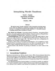
Fig. 3. BLDC Motor Rotor static eccentricity ζ: schematic of the reference system.
As regards the short-circuited coils, the voltage remains almost the same and the rotor resistance drops; as a consequence, a high circulating current arises and generates a localized heating in conductor that fuels the propagation. On the other hand, rotor static eccentricity be-longs to mechanical failures and consists in a misalignment between rotor rotation axis and the stator axis of symmetry. It is due to tolerances and imperfections introduced during motor manufacturing or to progressive escalation of wear of the rotor shaft bearings. Whenever it occurs, the motor, supposed to have more than one polar couple, generates a periodically variable magnetic flux, as the air gap varies during rotation (as schematically shown in figure 3) as a function of the rotor position ϑr: 𝑔𝑔�𝜃𝜃� � 𝑔𝑔� �� � � ����𝜃𝜃��
where
��
��
��
(1)
Taking into account coil short-circuit and rotor static eccentricity authors studied the effects of faults on EMA performances [14]. Failures and their effects on the electrical features of the BLDC motor (winding resistance, inductance and back-EMF) have been simulated through a simplified numerical model, according to [15]. In particular, according to [16], the authors simulated the effects of faults affecting the magnetic coupling between stator and rotor varying values and angular modulations of the back-EMF coefficients. Executed in the BLDC ElectroMec model block (see figure 2), this method acts on the three back-EMF constants Cei (one for each branch) modulating their trapezoidal reference values Kei as a function of coil short circuit percentage, static rotor eccentricity ζ and angular position ϑr: 𝑘𝑘𝑘𝑘� � �𝑘𝑘� ∙ 𝐶𝐶𝐶𝐶� ∙ �� � � ∙ ����𝜗𝜗� �� � � �� �� �
(2)
The so obtained constants (kea, keb, kec), called normalized back-EMF coefficients, are then used to calculate the counter-electromotive forces induced on the corresponding stator windings and, therefore, to evaluate the mechanical torque contributions generated by the three motor phases. As re-ported by Ginart et al. in [17-18], the evaluation of precursors permits to adopt countermeasures despite quite fast propagation of sensors’ and electrical components’ failures. 4
MATEC Web of Conferences 233, 231, 00017 (2018) https://doi.org/10.1051/matecconf/201823300017 (2018) https://doi.org/10.1051/matecconf/201823100017 GAMBIT 2018 EASN-CEAS 2018
It must be noticed that, with respect to other EM models available in literature, the numerical model shown in the previous sections is able to calculate the instantaneous value of each current phase (Ia, Ib, Ic) also in case of unbalanced electromagnetic system (e.g. partial short circuit on a stator branch or rotor static eccentricity); then, it is possible to correlate the progressive faults with the dynamic response of these signals (used as failure precursors) by means of an algorithm, based on the Wavelet analysis, that evaluates the filtered phase currents; for this purpose, each phase current is filtered by three low pass signal filter, in order to attenuate noise and disturbances.
5 Wavelet Neural Network Wavelet analysis can decompose any signal through a wavelet family basis, expanded from a wavelet basis function and locally refinement the high and low-frequency details while retaining the characteristics of the original signal in time domain. So wavelet analysis has good time-frequency proprieties and can effectively identify non-stationary signals for fault diagnosis purposes [19]. On the other hand, as the variety capabilities of handling nonlinear and self-learning and parallel computing, the neural network has great advantages for fault diagnosis for nonlinear systems. Wavelet transform is used to get characteristic values for each current signal. These Features and their trends can help to correlate fault symptoms to fault type and its intensity. A Feed-forward Neural Network, based on supervisedlearning method, is very suitable for fault diagnosis. There are two main ways for combination of wavelet transform and neural network: - Loose type: The wavelet analysis is used as a pre-processing mean and provides eigenvector for the neural network, which will conduct training and complete diagnosis. - Compact type: This is a feed-forward network based on wavelet analysis. The basic idea is to use wavelet element to replace the neurons, that is, the activation function is as the positioned wavelet basis function and the corresponding weights from input layer to hidden layer and the threshold of hidden layer are separately replaced by the scale and translation parameters of wavelet function In this paper, the wavelet analysis and neural net-work are combined with loose. 5.1 Wavelet analysis and features extraction Several simulations have been performed in order to estimate the system response in nominal and in faulty conditions. Every fault has been valued with one type of input: step command at 1 radians. This command saturates the EMA controller so that it is possible to reach the maximum unloaded actuation speed of the motor. Current and speed signals from the two progressive fault cases are compared below with their wavelet analysis. Several wavelet families have been tested on every signal and then, after qualitative comparisons, the best choice was made [20]. For all the type of faults and signals two steps was made: - comparison between Nominal Condition (NC) and a significant fault condition and choose of more representative wavelet family; - wavelet analysis for every fault intensity. Once test signals - acquired in a form of digitized data - are properly pre-processed, it is necessary to determine features from the raw signal by the use of digital processing techniques. This process is named “feature extraction” and, by an operatively point of view, it is a special form of dimensionality reduction. First of all, as shown in figure 4(a), it is necessary to compare the raw signal of NC with representative fault conditions (e.g. 20% of coils short circuit). The selection of the type of mother wavelet suitable for analysis is dependent on the properties of mother wavelet or the similarity between the considered raw signal and the said mother wavelets [21-23]. 5
MATEC Web of Conferences 233, 231, 00017 (2018) https://doi.org/10.1051/matecconf/201823300017 (2018) https://doi.org/10.1051/matecconf/201823100017 GAMBIT 2018 EASN-CEAS 2018
(a)
(b)
Fig. 4. Example of wavelet decomposition applied to phase current (a) and motor angular speed (b).
The same analysis was performed for angular speed and is shown in figure 4(b), but in this case a Db2 wavelet type has been selected because it is more similar to the signal waveform [23]. As widely described in [20], this procedure was carried on for every fault signal: after implemented each feature in Matlab, they were evaluated for the two classes of progressive faults. For instance, figure 5 shows the main Waveform Length features, calculated on A-phase current signal in case of progressive short circuit (SC) fault; bars represent a progressive growing fault. The next step is to choose, for two classes faults, the features and the related signal that represent the progressive fault in the best way.
Fig. 5. Example of waveform length features: A-phase current with progressive short circuit.
6 Proposed ANN fault detection algorithm According to [20], the proposed FDI neural network (ANN1) has the task to perform the classification of the fault: it is able to distinguish a short circuit fault of the stator coils from a fault of the rotor eccentricity. ANN1 is tested with a different target vector to perform also a quantification of two classes of faults with scars results. To achieve this type of classification a second neural network (ANN2) has been designed, which must perform both the classification and the quantification of the failure: it is able to distinguish between SC and RE faults, performing an accurate quantification. The network was trained by the training vector K and the target vector T. The training vector K consists of two section of 17 rows for 110 columns. Each rows represent one out of seventeen features discussed in the previous chapter and is characterized by the two classes of faults. Every column represents an increasing fault level of the three signals processed in section 5, plus other four signals (Ic, Va, Vb, and Vc). The target vector T consists of 2 equal sections of 220 columns, one for 2 rows; each column of the T vector is associated with a column of the K vector. 6
MATEC Web of Conferences 233, 231, 00017 (2018) https://doi.org/10.1051/matecconf/201823300017 (2018) https://doi.org/10.1051/matecconf/201823100017 GAMBIT 2018 EASN-CEAS 2018
The first row represents the short-circuit fault of the stator winding, while the second row represents the failure of the rotor eccentricity. At the beginning of the training procedure T is a null matrix, but, by entering the value of the corresponding error percentage in the required column, it is able to indicate to the neural network which combination of faults corresponds to a given case and and its percentage of the corresponding column vector K. The ANN2 (depicted in figure 6) is a feedforward multilayer perceptron NN and has been generated by Matlab tool [24].
Fig. 6. Schematic of the proposed ANN2 architecture.
The advantage of feedforward network, instead of pattern recognition network, is that this kind of net doesn’t require a Boolean target vector, it accepts a real value targets, that allow to achieved both classification and quantification. It has the following characteristics: - Layers: two hidden layers, one input layer, one output layer; two hidden layers are commonly needed to perform two different types of classification [24]; - Neurons: 90 perceptrons, 60 in the first hidden layer and 30 in the second one; - Activation Function: tan-sigmoid; - Training Function: ‘trainlm’, updates weight and bias according to L-M optimization; - Performance Function: ‘mse’ (mean square error), it measures the network's performance; - Division Data: ‘dividerand’, divide K into three sets using random indices following this percentages: 70% training samples, 15% validation samples, 15% testing samples. [25] This type of network requires more time to train and test, but offers greater accuracy.
7 Conclusions The principal issue, for a neural network and more generally for prognostics, is to preprocess output signals from sensors, since the network needs a separable set of data to accomplish an affordable classification. To this purpose, DWT seems to be a useful tool to elaborate the raw signals due to its time-frequency analysis: it is noticeable that the wavelet analysis easily detect fault condition and, like this case, a progressive one, both in time domain and frequency domain by change in amplitude and shape of its coefficients. Hereafter, from transformed signals, features can be extracted using statistical definitions and trends come out, linkable to classes of progressive faults. This analysis operates similarity to the discrimination processes in our brain. These features are used as inputs of a feedforward NN and, subsequently, this NN is trained to find a relationship that fit these inputs to targets, chosen to perform a specific non-linear classification between two classes of defects and their magnitude. This three-stage analysis presents some advantages. First, the wavelet analysis is faster than a Fourier analysis; as a matter of fact, the wavelet transform has a computational cost of O(N) instead of O(NlogN) of the Fourier analysis. Second, NN is a reliable approach for prognostics due to the large amount of data that can be collected and the increase of computer performance. For instance, the code used in this work needs the following calculation times: simulation: 17 [s]; DWT signal processing: ≈ 2,82 [s]; ANN training, validation and testing: ≈ 220 [s]. Future works could be carried out to increase the considered fault classes or to improve the reliability of wavelet analysis and the ANN architecture: to achieve these goals, it is necessary to devise quantitative methods to automatically perform the choice of a given wavelet family.
7
MATEC Web of Conferences 233, 231, 00017 (2018) https://doi.org/10.1051/matecconf/201823300017 (2018) https://doi.org/10.1051/matecconf/201823100017 GAMBIT 2018 EASN-CEAS 2018
Furthermore, in order to ensure the effectiveness and the robustness of the proposed FDI method, it’s necessary to test the trained network with inputs related to several noise levels.
References 1. 2. 3. 4. 5. 6. 7. 8. 9. 10. 11. 12. 13. 14. 15. 16. 17. 18. 19. 20. 21. 22. 23. 24. 25.
G. Vachtsevanos, F. Lewis, M. Roemer, A. Hess, B. Wu, Intelligent Fault Diagnosis and Prognosis for Engineering Systems (Wiley, 2006) D. W Brown, G. Vachtsevanos, Annual Conference of the PHM Society 2011, (2011) C. S. Byington, W. Watson, D. Edwards, P. Stoelting, IEEE Aerospace Conference Proceedings, (2014) P. Maggiore, M. D. L. Dalla Vedova, L. Pace, A Desando, Int. Journal of Prognostics and Health Management, 6 (2015) D. Belmonte, M. D. L. Dalla Vedova, P. Maggiore, Safety and Reliability of Complex Engineered Systems, Proc. of ESREL 2015, pp. 2365-2372 (2015) M. Çunkas, O. Aydoğdu, Mathem. and Comput. Applications, 15 218-229 (2010) A. Halvaei Niasar, H. Moghbelli, A. Vahedi, IEEE EUROCON 2009, 682 -687 (2009) B. K. Lee, M. Ehsani., Electric Power Components and Systems, 31(9) 841-868 (2003) T. Hemanand, T. Rajesh, India International Conference on Power Electronics (IICPE 2006), (2006) T. A. Haskew, D. E. Schinstock, E. Waldrep, IEEE Trans. on Energy Conversion, 14(2) (1999) L. Borello; G. Villero, M. D. L. Dalla Vedova, Aerospace Science and Technology, 13(8) 475-487 (2009) L. Borello, M. D. L. Dalla Vedova, G. Jacazio, M. Sorli, Annual Conference of the PHM Society (San Diego, CA) (2009) L. Borello, M. D. L. Dalla Vedova, Int. J. of Mechanics and Control, 13(2) 37-45 (2012). I. Todić, M. Miloš M. Pavišić, Tehnicki Vjesnik 20, 853-860 (2013). B. W. Kim, K. T. Kim, J. Hur, Journal of Power Electronics, 12 10-18 (2012) J. A. Farooq, A. Djerdir, A. Miraoui, COMPEL - The Int. J. for Computation and Mathematics in Electrical and Electronic Engineering, 27(4) 887-896 (2008) A. Ginart, D. Brown, P. Kalgren, M. Roemer, Autotestcon (IEEE) (2007) A. Ginart, D. Brown, P. Kalgren, M. Roemer, Applied Power Electronics Conference and Exposition (APEC) (2008) E. E Ngu, K. Ramar, R. Montano, V. Cooray, WSEAS Trans. on Signal Processing, 4 398-408 (2008) M. D. L. Dalla Vedova, N. Lampariello, P. Maggiore, WSEAS Trans. on Electronics, 8 21-26 (2017) J. Rafiee, P. Tse, A. Harifi, and M. Sadeghi, Expert Systems with Applications, 36(3) 4862-4875 (2009) W. K. Ngui, M. S. Leong, L. M. Hee, A. M. Abdelrhman, Applied Mechanics and Materials, 393 953-958 (2013) A. Phinyomark, A. Nuidod, P. Phukpattaranont, C. Limsakul, Electronics and Electrical Engineering, 112(6) 27-32 (2012) MATLAB® Neural Network Toolbox™,http://it.mathworks.com/help/nnet/index.html, The MathWorks, Inc., (2017) B. Sharma, K. Venugopalan, IOSR J. of Computer Engineering, 16(1) 31-35 (2014)
8