Jun 5, 2008 - The solution to this equation also called âarm solutionâ is in general ... Dimentberg in the 1950s and Freudenstein in the 1960s and 1970's were.
EngOpt 2008 - International Conference on Engineering Optimization Rio de Janeiro, Brazil, 01 - 05 June 2008.
New technique for inverse kinematics problem using Simulated Annealing Max Suell Dutra Ivanovich Lache Salcedo Liliana Margarita Prieto Diaz Robotic and Automation Laboratory – COPPE/UFRJ Federal University of Rio de Janeiro – UFRJ P.O. 68.503 – CEP 21.945-970- Rio de Janeiro, RJ, Brazil Abstract One interesting problem in robotics is the inverse kinematics; It consists in easy words to find the correct values for each one of actuators (or degrees of freedom) in a robotic system knowing the final position. Nowadays exist many techniques to solve this kind of problem but unfortunately some techniques require a lot of time and bring a restricted solution that in some cases (like redundant mechanism) is not the best one. This paper presents a new technique for inverse kinematics problem using Simulated Annealing technique; the authors implement a multi-objective cost function in order to find the intermediate set of angles for the transitional points in a trajectory, from the initial position to the final one. This methodology is compared with the classical inverse kinematics solutions in a different kind of examples and is presented the advantages of this technique like reduction of time (CPU processing) and the actuator’s energy consumption using this tool, besides, and comparison with other new techniques, is make and the results of the study is also presented showing the different advantages for the simulated annealing approach. Finally a future work is proposed for improving the results and to implement this technique in industrial problems. Keywords: Kinematics, Simulated Annealing, Optimization, Computational Methods. 1 Introduction For advanced control of robot manipulators, necessary capabilities are offline programming of the end effector path and control in terms of Cartesian coordinates. Although control of Cartesian trajectory of the end effector is a basic requirement for many industrial applications, most robot manipulators lack this ability. The “inverse kinematics” control of a robot manipulator requires the transformation of end effector Cartesian task space coordinates into corresponding joint configuration space coordinates. The common approach for solving this problem is to obtain a closed-form solution to the inverse transformation. However, only certain classes of robots (e.g., spherical wrist manipulators, such as the PUMA 560 robot) allow closed-form inverse kinematics solutions. The problem becomes more critical for kinematically redundant robots, for which the number of degrees of freedom (DOF) exceeds the required six coordinates necessary to attain arbitrary locations in the three-dimensional work space. [1] The kinematic transformation between task space and joint configuration coordinates is nonlinear and configuration dependent. A solution to the inverse kinematics is a vector of joint configuration coordinates that corresponds to a set of task space coordinates. For a class of robots closed form solutions always exist, but constraints on joint displacements cannot be systematically incorporated in the process of obtaining a solution. A solution is presented that is suitable for any class of robots having rotary or prismatic joints, with any arbitrary number of degrees of freedom, including both standard and kinematically redundant robots. The solution can be obtained subject to specified constraints and based on certain performance criteria. The solution is based on an exploratory study about the Simulated Annealing technique for optimization applications in inverse kinematics problem in engineering. This is a new optimization algorithm that has been developed in the recent years and has shown to be an important optimization tool. 2 How Simulated Annealing works. The Simulated Annealing technique is a probabilistic search algorithm capable of finding the global minimum amongst many local minima, particularly in the case where traditional techniques fail. Annealing is a term from metallurgy. In the process of annealing the metal is heated to a high temperature, causing the atoms to shake violently. Providing that the temperature drop is slow enough, the metal will eventually stabilize into an orderly structure. Otherwise, unstable atom structure is found. Simulated Annealing can be performed in optimization by randomly perturbing the decision variables and keeping track of the best objective function value for each randomized set of variables. After many tries, the set that produced the best objective function value is designated to be the center about which perturbation will take place for the next temperature. The temperature (the standard deviation of the random number generator) is then reduced, and new tries are performed. [4]
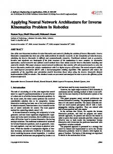
Figure 1. Flowchart of the optimization procedure.
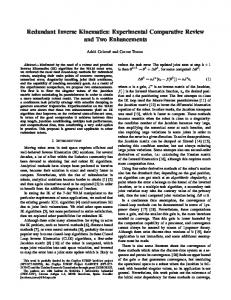
Figure 2. Simulated annealing computational scheme. 3 The Inverse kinematics problem (IKP). A robot arm is a combination of 'links' and 'joints' in the form of a chain with one end fixed while the other end is free. The joints are either prismatic or revolute, driven by actuators. In order to arbitrarily move the free end, also called the end effector, along a certain path, most, if not all, the joints are to be moved in order to track the desired path. In doing so it is necessary to know the displacements of the joints at each instant of time with respect to a fixed reference frame called the base frame in which the end effector's path is also defined. A kinematic model defines the position, velocity and acceleration of each link and the end effector without the consideration of mass and forces/moments. One of the robot arm kinematics problem is: given the joint displacements and the link parameters, find the position of the end-effector in the base frame; this is referred to as the forward /direct kinematics Problem. Thus for a given joint coordinate vector q and the global coordinate space X g we are to solve:
X g = f (q )
(1)
Where f is a nonlinear, continuous and differentiable function. This equation has a unique solution. The other called the inverse kinematics problem deals with finding the joint displacements for a given position and orientation of the end-effector in the global coordinates, i.e., solving the equation
q = f −1 (X g ) The solution to this equation also called “arm solution” is in general not unique.
(2)
The robot motion problem involves in bringing the end-effector of the manipulator from the present to the desired position and orientation in the global coordinates while following a prescribed trajectory in either the joint coordinates or global coordinates. Since the desired position is usually specified in the global coordinates, whereas the actuators used to drive the system are to be commanded with desired joint values, the inverse kinematics must be solved. [3] The inverse kinematics problem enjoys a rich history. Dimentberg in the 1950s and Freudenstein in the 1960s and 1970’s were seminal authors. With the realization in the late 1960s that a serial robot could be modeled as a spatial mechanism, the disciplined and analytical theory of mechanisms was applied to the exciting new field of robotics. This work dominated inverse kinematics research during the 1970’s as the search for a general closed-form solution for robots with six DOF became the “Mount Everest” of kinematics problems. Duffy, Pieper, and Roth were at the forefront of inverse kinematics research during this time. Within the context of redundant robots, the inverse kinematics focus shifted towards optimization and linear algebra. Whitney (1969) pioneered this work with his resolved motion rate control that suggests the use of the pseudo-inverse to resolve redundancy. Liegeois (1977) showed the extension of this method to include self-motions via the null-space. A number of other searchers have developed and implemented rate control methods. Notable approaches include: Seraji’s (1992) configuration control, Baillieul’s (1986) extended Jacobian, and the Jacobian transpose (1988). Several approaches optimize task-based performance measures in the redundancy resolution (1988). Maciejewski (1989) discusses the kinetic limitations of redundant robots. Generality is the main advantage rate control methods enjoy over closed-form methods. With little (if any) modification, rate control methods will solve the inverse kinematics problem for robots with a wide range of geometries. [2] 4 Introducing the SA to solve the IKP The simulated annealing is in a simple way a computational technique with the ability to solve optimization problems, like was present in the last section the IKP is an special kind of optimization problem, for that reason the authors of these article started to think in a easy way to integrate the SA and the manipulator’s kinematics information in order to obtain a good practical answer, in addition an second objective was launched into the SA, a generation of the trajectory for the manipulator, this combination, solve the IKP and generate the trajectory was introduce to the optimization problem and its presented in this article. In order to solve the IKP is necessary to know the kinematics of the robot; kinematics describes the motions of objects without the consideration of the masses or forces that bring about the motion, this information is in many cases easily to know or to calculate, for a robot exist many techniques to calculate the position of the final actuator knowing the values of the respective degrees of freedom, this information will be the base for the SA cost function. The idea to use the kinematics information for the cost functions is simple to argue, whit this information is possible to evaluate a good or a bad set of solutions, is important to remember at this point that in a robot of n degrees of freedom the SA will evaluate n different values each iteration and a cost of function will be necessary to rank each solution, the kinematic information is a function that depends of the values for the n degrees of freedom and its value represent the special position for the actuator, for that reason is necessary to evaluate this information for each presented solution, in a first approach the cost function only will the set point (the desire position) minus the position obtained with the present set of solutions x that is represent in the equation (1), the first cost function will be appear in equation (2).
x = [ v1 , v2 ...vn ]
(1)
c ( x ) = Sp − p ( x )
(2)
Where c is the cost function, Sp the set point and p the position that depends of the estate vector x that has information of the set of values for each degree of freedom, this primary cost function lets to the SA know if the x present for the algorithm generates values that will leave the actuator for the desire position, so the optimization problem know is presented, minimized the cost function c. Whit this primary cost function is possible to obtain a good set of partial solutions, with this solutions is possible to generate the trajectory for the actual point of the manipulator to the desire position, this is possible because the set of initial values given to the SA is the actual value of degrees of freedom, with this simple idea and using only the solutions that represent and improvement in values for the cost function is possible to obtain a rustic trajectory for the actual position to the desire position. The problem seems to be solved, but unfortunately the trajectories obtains with the primary cost function wasn’t soft enough to apply in real situations, the problem was that the cost function only is worry about the distance between the partial solution position and the final position, for that reason was necessary to modify the cost function and include some information that let the SA chose a better partial solution without lose the performance finding, the new cost function include the information of the change of the value of the solution and the better solution found until that moment. The new cost function improve the set of partial solution and still find a good final set of values, the new cost function can see at equation (3). n
c ( x ) = Sp − p ( x ) + k ∑ ( xb − x )
(3)
i =1
Where xb is the best set of values founding until that iteration of the SA and k represents a constant that can increase the importance of the trajectory softness in the cost function, this cost function was applied in the SA and as result of this modification the set of
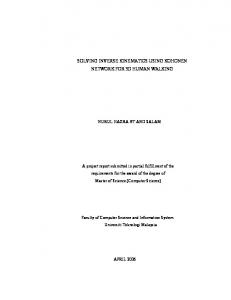
values of the intermediate positions will let the manipulator to have a soft trajectory in order to accomplish the final position. 5 Example using SA In order to evaluate the performance of the technique was implemented an example using a simple manipulator configuration, was used a robot with two degrees of freedom like is show at Figure 3.
Figure 3 Manipulator tested At Figure 3 is possible to see the two degrees of freedom for the actuator represent by
θ1
and
θ 2 , and two links l1 and l2, for this
example the distances was set up in 1m, this simple configuration will be used in this section in order to show the performance of the algorithm. The kinematics of the actuator is
xa = l1 cos (θ1 ) + l2 cos (θ 2 ) ya = l1 sin (θ1 ) + l2 sin (θ 2 ) This information is used to calculate the position of the actuator using the values of θ1 and θ 2 proposed by the algorithm, if exist some improvement in the cost function, the set of that angles are saved and used like intermediate point in the trajectory generation. 5.1 Primary cost function. In this particularly example was proposed a initial position at x=[0,0] that leave the manipulator at the final position in X=2m and Y=1m, the desire position is set up at Xs=1.8m and Ys=0.2m, the cost function implemented was the primary cost function (see equation (2)): with this conditions was set the parameter in the algorithm and make a first simulation, as a result is possible to see the evolution of the initial position until the desire position at Figure 4 After that was computed the cost evolution, it is possible to see at Figure 5 and show how the angles proposted by the algorithm decrease the values of the cost function; this first experience is using the primary cost function, for that reason that values represents the distance in meters between the target and the position set by the SA, in that figure is possible to see an evident decrease of the values for the cost function, at this point is important to remember that the cost value in all SA process does not have this performance, it is obtained because only was displayed (and taken for the trajectory) the cost and set of angles that represent and improvement in the cost function, this is very important in order to obtain a softly trajectory.
Figure 4 Workspace for Xs=1.8m and Ys=0.2m
Figure 5Cost improvement 5.2 Primary cost function performance. The second test was implemented using the same conditions (initial position, desire position and length of the links) 200 times, the results of the final cost (that shows how close was the final values of the SA with the desire position) was computed and make an histogram that helps to visualize the performance of the SA for the same point, as is possible to see at Figure 6 the repeatability and the precision of the results in the same way the results of the SA never go up to the 0.4mm that is important for the industrial applications that in many cases precise accuracy under 1mm.
Figure 6 Histograma In the same line of test was make an interested one, the idea was to calculate the performance of the cost depending on the final point, as was expected, if the desire point is close to the initial point, the performance of the SA is better, it is obvious because the number of iterations of the iterations that take the SA to find a good solutions depends on the amplitude of the state variations. This information is possible to see that effect at the Figure 7.
Figure 7 Final cost value at different desire points
5.3 Implementing the new cost function The next test was implemented using the new cost function; the idea was increase the distance that the manipulator has to move, like was see at the Figure 7 the precision of the technique seems to be inversely proportional for this reason was used the same initial condition x=[0,0] and the desire position at Xs=-1.4m and Ys=0.4m. the workspace obtained is possible to se at Figure 8 and the cost evolution at Figure 9.
Figure 8 Workspace
Figure 9 Cost evolution Finally was computed 200 times the algorithm for the same conditions, was taken the final values of the cost function and make an histogram, it is at Figure 10. This histogram at been compared with the first one at Figure 6 show and apparently decrease of the precision, but is important to say that the new Multi-Objective function not only represents the distance in meter from the actual point to the desire point this cost function contains the information of the angle variations, for that reason the values given in the histogram do not represent the distance, however the magnitude of this cost function is still little and as was see at Figure 9 the accuracy of the new cost function still work under the industrial requirements.
Figure 10 Histogram Multi-Objective cost function
5.4 Maximum translating The next test was implemented using the new cost function; the idea was increase the distance that the manipulator has to move, for this reason was used the same initial condition x=[0,0] and the desire position at Xs=-2m and Ys=0m with this information the SA is
working at the most difficult conditions, the results is possible to see at Figure 11 and Figure 12.
Figure 11 Workspace
Figure 12 Cost Improvement The values shows that even in that conditions the algorithm is able to find a solution with the necessary accuracy. 5.5 Angle Variations. For the last test was computed the angle variations for two conditions, the first one, the primary cost function, the results is possible to see at Figure 13 and the second one with the Multi-Objective cost function at Figure 14; Is possible to see the variations of the angles are bigger in the first test than the second test this show and probe the effect off implementing the information of the variation in the angles and punish that variations.
Figure 13 Angle variations (Primary cost function)
Figure 14 Angle variations (Cost function improved)
6 Conclusions an future work. This work demonstrate that is possible to use Simulated annealing in order to present a very good and reliable solution to the Inverse kinematics problem (IKP), this technique demonstrate that solve the IKP even on the singularities of the problem, when the derivate of the kinematics is zero, the same values where the classic ways to solve, that uses de gradient of the kinematics, does not present any practical solution. At the same time, is important to say that this technique is easily scalable because its principal component is the kinematics information that in the majority of the cases is very simple to calculate, in the other hand the classic methods precise to calculate the gradient of that function increasing the number of calculations. Finally the authors express his interests in study, as a future work the performance of this algorithm when a very large number links are used (redundant manipulators) and a new restrictions are implemented (environment, energy consumption). 7 References 1. Guez, A.; Ziauddin A. Solution to the inverse kinematics problem in robotics by neural networks. Department of Electrical and Computer Engineering. Drexel University. United States. 1988. 2. Duarte Faria E. Saramago S. Optimizaçao utilizando Simulated Annealing. Brazil. 3. Hopper R. A Simulated Annealing optimization algorim implemented within na Operator-Assist Interface. Department of Mechanical Engineering. The University of Texas at Austin. United States. 1997. 4. Goldenberg A. Benhabib B. Fenton R. A complete generalized Solution to the inverse kinematics problem of robots. IEEE Journal of robotics and automation. Vol. Ra-1. No 1. 1985.