the growth conditions, in particular for the V to III fluxes ratio, for obtaining such layers. It is also observed ... introduction of an nipi delta-doping superlattice in a.
269
Brazilian Journal of Physics, vol. 32, no. 2A, June, 2002
nipi
Delta-Doping Superlattices for Amplitude Modulation �
C. V.-B. Tribuzy, S. M. Landi, M. P. Pires, R. Butendeich,
P. L. Souza,
Laborat� orio de Semicondutores, Centro de Estudos em Telecomunica� c~ oes,, Pontif� �cia Universidade Cat� olica do Rio de Janeiro, Rua Marqu^ es de S~ ao Vicente 225, Rio de Janeiro, 22453-900, Brazil
A. C. Bittencourt, G. E. Marques, Instituto de F� �sica, Universidade Federal de S~ ao Carlos, S~ ao Carlos, 13565-905 Brazil
and A. B. Henriques Instituto de F� �sica, Universidade de S~ ao Paulo, S~ ao Paulo 05315-970, Brazil
Received on April 23, 2001 GaAs/AlGaAs multiple quantum well structures containing an nipi delta-doping superlattice, where the n-type doping is inserted in the quantum wells and the p-type in the barriers, have been studied in detail to evaluate their potential for use in the fabrication of amplitude modulators. It is shown that C is an adequate p-type dopant for such structures, however, little exibility is found in the growth conditions, in particular for the V to III uxes ratio, for obtaining such layers. It is also observed that the required balance between n and p type doping levels is not trivial to be achieved due to the presence of interface hole traps whose population depends on the quantum well doping concentration. In addition, the observed photoluminescence near-edge emission at room temperature occurs at essentially the same energy as that of an equivalent undoped structure. Finally, no deep level emissions are observed which could deteriorate the device performance.
I Introduction
the Stark shift.
If the nipi -MQW structures are expected to be used Recent demands for multiterabit communication rein amplitude modulators some requirements should be quire external amplitude modulators operating at low ful led. The presence of the nipi delta-doping supervoltages. Amplitude modulators based on the Quanlattice should not introduce energy levels in the fortum Con ned Stark E�ect (QCSE) in III-V semiconbidden gap, otherwise, in the ON state of the device, ductors multiple quantum well (MQW) systems are light could be absorbed, dramatically increasing insersuitable for meeting these technological demands and tion losses. For applications in amplitude modulators, therefore, much attention has been devoted to their where the MQWs form the active region of the device, development1;2 . One of the crucial requirements for it is crucial that the net doping corresponds to an uneÆcient modulation at high bit rates is that the change doped structure, so that the applied electric eld is uniin absorption per applied voltage be as large as possiformly distributed over the entire MQW region. It is ble. In other words, the Stark shift should be maxtherefore essential to balance out the electron and the imized. The larger the quantum well is, the larger hole concentrations in the delta layers. In this artithe Stark shift3 . However, increasing the quantum well cle, rst, results of a thorough investigation of C deltawidth decreases the oscillator strength for absorption. doping of AlGaAs grown by MOVPE using CBr4 as Thus, a compromise is imposed. An alternative for inthe C source are presented. Much attention is devoted creasing the Stark shift has been proposed by Batty to the changes in doping level as a function of the V and Allsopp4 . They have theoretically shown that the to III uxes ratio, V/III. It is experimentally shown introduction of an nipi delta-doping superlattice in a that only within a small range of this ratio it is posMQW structure, where the quantum well is n-deltasible to obtain C delta-doped AlGaAs layers with all doped while the barrier is p-delta-doped, may double � On leave from the Physikalisches Institut, University of Stuttgart, Germany.
270 the properties required for the fabrication of amplitude modulators. Second, it is shown that in GaAs/AlGaAs nipi -MQW structures the fundamental optical transition is basically not shifted with respect to that of the undoped structure and no optical transition below the fundamental gap at room temperature is observed. Finally, transport measurements demonstrate that the p doping eÆciency changes when MQWs are grown with n and p dopants in the QWs and in the barriers, respectively. This renders the balance of n and p doping more delicate to be achieved.
II Experimental details All samples were grown by metalorganic vapor phase epitaxy on an AIX 200 reactor at 630o C and 100 mbar. TMGa, TMAl, AsH3 , SiH4 and CBr4 were used as Ga, Al, As, Si and C sources, respectively. For the C doped layers, on a Cr-doped (100) oriented GaAs substrate, after a 500 � A thick undoped GaAs bu�er layer a 2000 � A thick AlGaAs layer homogeneously doped with C was deposited. The Al content in the alloy is 28%, as determined by x-ray measurements. In the case of the delta-doped samples, C was introduced during growth according to the following sequence. After a 1000 � A thick undoped AlGaAs layer was grown, the TMAl and TMGa were switched o� for 15 seconds while the AsH3
ux was switched from a high to a low value. Then the Ga, Al and C sources were switched on for 2.5 seconds. After this short period these sources were switched o� for 10 seconds while the AsH3 ux was raised to the original high value. At this point, the TMAl and TMGa were turned on and another 1000 � A thick undoped AlGaAs layer was grown. The arsine ux should be such that minimizes C incorporation during growth of the undoped layer and optimizes it in the doped layer. Thus the AsH3 ux has to be changed during the growth of the delta-doped samples. Various V/III and CBr4 uxes were used for the growth of the samples. Before removing the samples from the reactor chamber they were all annealed at 600oC for 15 minutes in N2 for removal of H atoms. For the GaAs/AlGaAs MQW samples, a 300 � A GaAs bu�er layer was rst grown followed by a thick AlGaAs layer which was delta-doped 25 � A before the growth of the MQW layers. The MQW structure consists of 20 periods of 100 � A thick GaAs QWs, n-delta-doped using Si in the center, and 50 � A thick AlGaAs barriers, C deltadoped in the center. The last barrier is 500� A thick and its C delta layer was introduced 25 � A from the last grown QW. Growth interruption was used to produce the Si delta-doped GaAs layers. The current carrier concentration and mobility were determined by Hall e�ect measurements at room tem-
C.V.-B. Tribuzy et al.
perature (RT) and at 77 K using an HL 5500 equipment. The capacitance vs. voltage (C-V) pro les were obtained by the electrochemical pro ler PN 4300 to determine the delta layers localization both in GaAs and AlGaAs. The photoluminescence (PL) measurements were carried out with the 514 nm line of an Ar+ laser for excitation. The signal was dispersed by a 250 mm monochromator and detected by a Ge nitrogen cooled photodetector. PL experiments were performed for temperatures between 20 and 300 K.
III Results and discussion First, the diÆculties and results involving C deltadoped bulk AlGaAs layers will be addressed, followed by the results of Si delta-doped GaAs bulk layers. Then, results on GaAs/AlGaAs MQW containing either n or p delta-doped layers centered in the QW and in the barrier, respectively, will be presented and discussed. Finally, the results obtained with the nipi MQW samples will be reported and analysed.
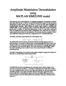
Figure 1. Full width at half maximum (FWHM) of the capacitance versus voltage pro les (CV) in units of the Bohr radius (aB =11.4 � A) as a function of the areal net hole concentration, P2D , in units of aB2 . The solid line corresponds to the theoretical calculations, the squares refer to the experimental results of this work while the other data points correspond to data from the literature as speci ed by the labels. The inset shows the CV pro le for one sample, where the solid line is the simulation for an impurity con nement equivalent to a gaussian of 5 � A width while the scattered points correspond to the experimental data.
The solid dots in the inset of Fig. 1 represent the net hole concentration, [P], for one typical C deltadoped AlGaAs sample obtained by CV measurements. The CV full width at half maximum (FWHM) is 39 � A and the integral of the CV pro le gives a value of 1 x 1012 cm 2 for the areal hole concentration5. The solid line is a theoretical calculation, where the Poisson and Schrodinger equations were solved self-consistently
Brazilian Journal of Physics, vol. 32, no. 2A, June, 2002
within the Hartree approximation, assuming the impurities follow a gaussian distribution of width equal to 5� A, in the same way as it has been previously done for Si delta-doped InP6;7 . A single heavy hole subband was taken into account in the calculations, given that the Fermi energy in the structures considered was always smaller than the energy separation between decoupled heavy and light hole subbands. The solid line in Fig. 1 shows the theoretical CV FWHM ( in units of the heavy hole Bohr radius, aB =11.4 � A) as a function of the two dimensional hole concentration (in units of aB2 ) for an atomic C localization of 5 � A, P2D . The triangles represent the samples grown for this work, while the other data points refer to results from the GaAs literature8 11 . Points above the solid line correspond to a con nement over a region wider than 5 � A. In order to obtain such narrow con nement of the C atoms and a controlled high doping level, around 1 x 1012 cm 2 , several C-doped layers were grown using different CBr4 uxes and various V/III. Fig. 2 shows [P] as a function of the CBr4 ux for these samples. The V/III values used are shown in the inset. The solid symbols correspond to delta layers while the open ones correspond to bulk-doping. The points on the Y axis, are the residual doping levels achieved for the di�erent V/III values, meaning CBr4 ux equal to zero.
Figure 2. Net charge concentration as a function of the CBr4 ux. The solid symbols correspond to delta-doped layers and the open ones to bulk-doped layers. The V to III
uxes ratio used for the growth of the di�erent samples are indicated in the gure.
One of the highlights of Fig. 2 are the extremely high doping levels achieved for V/III values below 10 due to the many sites V available for C atoms. However, as the CBr4 ux increases, little or no changes in the doping level is observed, meaning that one has no real control over the doping. With such low V/III, not only C from the CBr4 is incorporated but also from the TMGa and TMAl. This is the intrinsic doping regime. On the other extreme, for high V/III, only low or moderate doping levels are achieved. In the case of
271 V/III=100, the C residual doping is the lowest. Therefore, this ratio was chosen for the high AsH3 ux used to grow the undoped parts of the AlGaAs layers. Comparing the delta-doped samples with the bulkdoped ones for V/III equal to 15 in Fig. 2, one observes the same behavior of [P] with the CBr4 . For the required doping levels for the nipi amplitude modulators and other devices4;6;12 , [1 x 1018 cm 3 ,5 x 1019 cm 3 ], a very narrow range of V/III can be used. For the growth rate and Tg used in this investigation this interval is 15 to 30, as depicted in Fig. 2. In other words, one should keep in mind that despite its advantages, the C doping of AlGaAs leaves little exibility in terms of growth conditions for some device applications. Bulk GaAs layers delta-doped with Si were grown to optimize the impurity spatial distribution. C-V pro les were measured and typical FWHM of 65 � A were observed for a doping level of 2.0 x 1012 cm 2 . This value is 20 % below the theoretical resolution predicted in references 5 and 7, implying in an impurity atomic localization of less than 10 � A, comparable to the best previously reported results5;8 . GaAs/AlGaAs MQW samples were then grown containing either n-type doping in the QW or p-type doping in the barrier in order to calibrate the electron and hole concentrations. The measured free electron concentration per doping plane, N , as a function of the silane ux for 100 � A thick GaAs QWs showed a linear behavior for a SiH4 ux between 0.1 and 3.5 sccm. The mobility of the samples at RT is reduced as the doping level increases, as expected. Essentially no changes in mobility occur when the measurement temperature is lowered to 77 K, because the mobility is limited by ionized impurities. It should be noted that the n-doping plane introduces a V-shaped potential well for electrons in the GaAs QW, so the free electrons are localized in the same region as the ionized Si atoms. The same types of measurements were performed in MQWs containing only p-type delta-doping in the center of the barriers. The two external barriers have half the doping level of the internal ones. The free hole concentration per doping plane, P , as a function of the CBr4
ux for the range between 2 and 20 sccm, also shows a linear behavior. The RT mobility of the C doped samples however is independent of the CBr4 ux. In this case, the p-type doping planes are in the barriers where they introduce an inverted V shaped potential, nevertheless part of the hole density moves into the QWs, staying far from the ionized impurities. This point will be re-addressed and further discussed. When no QWs are present, as in AlGaAs bulk material having a single C-doping plane, the mobility is lower because the holes remain close to the impurity plane. In addition, if the Hall measurement temperature is lowered to 77 K, contrary to the Si delta-doped MQWs, the mobility increases indicating that it is limited by phonons and not by ionized impurity scattering.
272 Having obtained the optimized growth conditions for the MQWs containing either types of doping, the nipi -MQW samples were grown using the calibration previuosly made with the purpose of obtaining essentially intrinsic material where P and N should be equal. However, the Hall measurements showed that the net free carrier concentration was heavily n-type. Assuming that the atomic incorporation is unchanged, either the electrical activity of the p-doping is reduced in the presence of Si atoms in the well or that of n-doping is improved in the presence of C atoms in the barriers. In trying to understand this e�ect, nipi -MQW samples with di�erent silane uxes were grown and the net free carrier concentration measured by Hall e�ect. Subtracting these values from those predicted using the previously obtained calibration curves, one obtains the concentration of \lost" free holes which is graphed in Fig. 3 as a function of the silane ux. One clearly sees that the concentration of \lost" free holes increases with the SiH4 ux. Moreover, the rate of increase is the same for the two di�erent CBr4 uxes, if a linear dependence is assumed, as depicted by the two solid lines in Fig. 3. In addition, extrapolating for zero silane
ux, one nds that the density of holes lost for the undoped QWs increases with the CBr4 ux. In the case of zero SiH4 ux, the di�erence between the C atomic concentration, measured by SIMS, and the free hole concentration, measured by Hall, is in full agreement with the density of \lost"holes, shown in Fig. 3.
Figure 3. \Lost" free holes as a function of the SiH4 ux. These values are obtained from the subtraction of the measured net free carrier concentration for the MQW structures containing an nipi Æ -doping superlattice (nipi -MQW) from that predicted by the calibration.
The increase in \lost" holes with the silane ux can be understood as follows. The solid lines in Fig. 4 show a scheme of the potential for the nipi -MQW structure, while the dashed and solid lines correspond to the di�erent hole probability densities, F (z )�xF (z ), as labeled. With the presence of a plane of ionized Si atoms the QW is, in fact, divided into two half QWs. In the QW valence band the hole probability density corresponding
C.V.-B. Tribuzy et al.
to the fundamental energy level will be peaked closer to the interfaces, while in the case of an undoped QW, it will have its maximum in the center. In addition, the larger the Si atomic concentration, the deeper the V-shaped potential in the QW, and consequently, the closer to the interface the hole probability density peak is. Thus, in the presence of hole traps in the interface, the introduction of an n-type doping plane in the QW will certainly lower the eÆciency of the p-doping in the barriers. Moreover, this eÆciency is directly dependent on the n-type impurity concentration. Further support for the substantial presence of holes close to the interfaces is encountered in the PL spectra.
Figure 4. Scheme of the potential for a QW n delta-doped in the center with p delta-doped barriers. Also included are the hole probability densities for the di�erent energy levels. The solid lines correspond to the hole probability density inside the GaAs QW while the dashed lines correspond to the hole probability densities in the inverted V-shaped potential in the AlGaAs barriers. The subscripts B and QW refer to the barriers and the quantum well, respectively.
The RT PL spectra of the nipi -MQW samples showed no emission below the fundamental gap. The near-edge optical transition was a few meV above that obtained for a sample with exactly the same MQW structure but undoped, which was used as reference. These results indicate that the introduction of the delta-doping superlattice should not harm the optical properties of the MQW structure for use in amplitude modulators. PL measurements as a function of temperature however, revealed di�erences in the optical properties between the doped and the reference samples. Fig. 5 shows how the PL peak energy changed with temperature for both samples. The lines are theoretical calculations to be described below. The reference sample, represented by solid circles, behaves as should the optical transition corresponding to the rst electron-heavy hole transition in the QW, (e1QW -hh1QW ), as depicted by the dashed line in Fig. 5. For the doped sample, the PL spectra as a function of temperature show that there exist two di�erent emissions, one at low temperatures which reduces in intensity as the temperature is raised
273
Brazilian Journal of Physics, vol. 32, no. 2A, June, 2002
and another one at higher energy which is only observable at higher temperatures. At temperatures above 90 K, this second emission dominates the spectra. In order to better understand these results, calculations of the temperature dependent electronic structure, within the full k.p Hamiltonian model were performed, where a triangular potential model (Fig. 4) was used to simulate the localization of the carriers in each doped layer, at their nominal densities. At low temperatures (below 50 K), the experimental PL results are best described by the transition between the rst QW electron and the rst barrier heavy-hole levels (e1QW -hh1B ); the corresponding hole probability densities of the di�erent energy levels involved are depicted in Fig. 4. Such transition is spatially indirect. At temperatures above 90 K, the experimental results follow the temperature behavior of the transition between the rst QW electron and rst barrier light hole levels (e1QW -lh1QW ) which is direct and only a few meV below the (e1QW hh1QW ) transition of the equivalent undoped sample, as illustrated in Fig. 5. Thus, around 90 K the PL emission su�ers a transition from indirect to direct. Experimental support for this change in nature is found in the results of PL as a function of excitation power (P). The PL peak energy of the emission at low temperatures is blue-shifted with increasing P, which is the standard behavior for spatially indirect transitions13 , while that of the emission at high temperatures is una�ected by P, indicating a direct transition. Since at RT the (e1QW -lh1QW ) transition dominates, one concludes that the lh1QW level, in the half QW, is indeed populated, demonstrating that holes are transferred from the barrier into the QWs. As a consequence, part of the transferred holes, being close to the interface as shown by the probability densities in Fig. 4, are most likely trapped by interface states.
IV Summary GaAs/AlGaAs MQW structures containing an nipi delta-doped superlattice were investigated in order to evaluate their potential for use in high performance amplitude modulators based on the QCSE. First, it has been shown that it is possible to obtain suitable C deltadoped AlGaAs layers even though little exibility is left in choosing the growth conditions for a controlled C doping of AlGaAs layers. Second, it has been demonstrated that to achieve the required balance between the n and p type doping levels one should consider the existence of hole traps at the interfaces whose occupancy depends on the QW n-doping level. Finally, PL measurements have shown that at RT only the nearedge emission is observed, and it is only a few meV below the fundamental transition of an equivalent undoped QW, not impairing, in principle, the use of such structures in the fabrication of amplitude modulators.
Figure 5. PL peak energy as a function of temperature. Solid circles represent the measurements for the reference sample whose behavior follow the electron-heavy hole transitions (e1QW hh1QW ), represented by the dotted line. Open squares are obtained from the measurements for a MQW structure containing an nipi Æ -doping superlattice (nipi -MQW). At high temperatures (above 90 K) the experimental points are best described by the (e1QW lh1QW ) transition, which involves electron and hole levels inside the GaAs QW (direct transition). At low temperatures, the experimental points are best described by the (e1QW hh1B ) transition from the rst electron level in the GaAs QW to the rst heavy hole level in the AlGaAs barrier (indirect transition). At intermediary temperatures (50-90K) the experimental points are described by the (e1QW lh1B ) indirect transition which involves the QW electron and the barrier light- hole levels. The probability densities for the holes, which participate in the emissions described above, are schematically shown in Fig. 4.
Q
Q
Q Q
Acknowledgements
This work has been partially nanced by CNPq, CAPES, FAPERJ, ERICSSON and FAPESP.
References [1] M. K. Chin and W. S. C. Chang, IEEE J. Quantum Electron. 29, 2476 (1993). [2] T. Ido, H. Sano, D. J. Moss e H. Inoue, J. Lightwave Technol. 14, 2324 (1996). [3] G. Bastard, E. E. Mendez, L. L. Chang and L. Esaki, Phys. Rev. B 28, 3241 (1983).
274 [4] W. Batty and D. W. E. Allsopp, Electron. Lett., 29, 2066 (1993). [5] E. F. Schubert in Semicondutores and Semimetals 40, chapter 1, edited by A. C. Gossard, Academic Press, New York (1994). [6] B. Yavich, P. L. Souza, M. P. Pires, A. B. Henriques, and L.C. D. Gon�calves, Semicon. Sci. and Technol. 12, 481 (1997). [7] P. L. Souza in InP and Related Compounds: Materials, Applications and Devices, edited by M. O. Manasreh, chapter 6, (2000). [8] B. R. Davidson, L. Hart J. , R. C. Newman, T. B. Joyce T. J. Bullough and C. C. Button, J. of Mat. Sci.: Materials in Electronics 7, 355 (1996). [9] T. Makimoto and N. Kobayashi, Jpn. J. Appl. Phys. 32, L1300 (1993).
C.V.-B. Tribuzy et al.
[10] N. Kobayashi, T. Makimoto and Y. Horikishi, Appl. Phys. Lett. 50, 1435 (1987). [11] M. B. Johnston, M. Gal, G. Li and C. Jagadish, J. Appl. Phys. 82, 5748 (1997). [12] F. Brunner, T. Bergunde, E. Richter, P. Kurpas, S. Gramlich, I. Rechenberg, S. Kraus, M. Achouche, J. Wur and M. Weyers, Proceedings of the EWMOVPE VIII, Prague-1999. [13] Y. Gong, J. Mo, H. Yu. L. Wang and G. Xia, J. Crys. Gr. 209, 43, (2000). [14] G. E. Ho er, H. J. Ho er, N. Holonyak, Jr. and K. C. Hsieh, J. Appl. Phys. 72, 5318 (1992). [15] P. Abraham, M. A. Garcia Perez, T. Benyattou, G. Guillot, M. Sacolotti and X. Letartre, Semiconductor Science and Technology 10, 1585 (1995).