NLOS detection algorithms for UltraWideband localization Jens Schroeder, Stefan Galler, Kyandoghere Kyamakya, and Klaus Jobmann
Abstract — Non Line of Sight (NLOS) channels are one of the major drawbacks for accurate ranging and localization with Ultra-Wideband (UWB) technology. Whereas several proposals exist to detect these situations, a comprehensive overview, investigation and testing of these methods has to the authors’ knowledge not yet been prepared. This paper tries to fill this gap with a classification of the algorithms proposed of the UWB and mobile phone community. In addition, one novel method based on the signal power variation is proposed. Afterwards, the methods are evaluated regarding their practicability for real UWB localization systems, which excludes some of them from further investigation. For the remaining algorithms thresholds are proposed, which are strived to be as independent of the system and environment as possible. Finally, the NLOS detection algorithms are tested and compared with both an UWB simulation environment and an UWB localization test bed.
I. INTRODUCTION
AND PROBLEM DESCRITPION
Ultra-Wideband (UWB) is perceived as one of the enabling technologies for robust and accurate localization, especially in harsh channel environments like e.g. indoor areas. Although UWB has its benefits for solving this task, several conditions have to be fulfilled to take advantage of them: – the signal structure must enable the receiver to detect the arrival time as exactly as possible, – the signal must have the possibility to travel a direct Line of Sight (LOS) path, and – the receiver must detect the correct LOS path in multipath and interference environments. Due to transmitting very short pulses, the inherent broad bandwidth in combination with an appropriate receiver architecture mainly accomplishes the first condition. However, the second and third conditions are affected not only by the receiver architecture but also Manuscript received Feb. 16, 2007. This work was supported in part by the DFG (German Research Foundation) under Grant KIOP, and the Minna-James-Heinemann Foundation. J. Schroeder, S. Galler and K. Jobmann are with the Institute of Communications Engineering (IKT), Leibniz Universität Hannover, Hannover, Germany (contact email:
[email protected]). K. Kyamakya is with the Institute of Informatics Systems, University of Klagenfurt, Klagenfurt, Austria.
heavily by the environment of the localization scenario. This so-called Non Line of Sight (NLOS) problem has been identified to be one major source of ranging error [1, 2]. If e.g. persons, objects or walls attenuate or block the direct signal, a typically positive ranging offset will occur, and mostly appear as a bias in the position error. This especially becomes critical if the minimum number of LOS channels needed for a position solution is not available. Three different channel conditions have been categorized in [3]. The first one is the dominant direct path (DDP) case, in which the strongest path of the channel estimate corresponds to LOS. Those channel profiles, where the first path is not the strongest, however still detectable by an appropriate receiver architecture, are called nondominant direct path (NDDP). Finally and only regarded as NLOS in this paper are the situations, in which the receiver architecture is not able to detect the direct path anymore. This case has been defined as undetected direct path (UDP) and leads to the mentioned ranging errors. Two consecutive strategies can be utilized to deal with such UDP situations. The first goal is to sense if such a situation occurs and can be denoted as NLOS detection. If this task has been succeeded, the second strategy is called NLOS mitigation. The main idea is to use the information that one or more channels are NLOS and try to still get an appropriate position estimate. Even though the two tasks are closely interrelated, the authors try to give a contribution only to the NLOS detection task, since not much comparative and practical work has been done in this field. In this context it is not relevant if the localization system is based on a time of arrival (TOA) or a time difference of arrival (TDOA) strategy. Even in the TDOA case the receiver is usually able to estimate each channel via template correlation, however, with an unknown time offset. In chapter II a comprehensive overview of existing NLOS detection algorithms of the UWB, but also of the mobile phone community, is given. In addition, one novel method based on the signal power variation is proposed. Afterwards the methods are evaluated regarding their practicability for real UWB localization systems, which excludes some of them from further investigation. The selected NLOS detection methods, which the authors think to be functional in reality, are
further described in more detail in chapter III in conjunction with proposals for threshold setting for each method. Chapter IV explains the UWB localization simulation environment and the UWB localization test bed, which is used in chapter V to test and compare the different NLOS detection algorithms. Finally, chapter VI concludes this paper. II. CLASSIFICATION AND PRACTICABILITY NLOS DETECTION ALGORITHMS
OF
A. Detection based on range estimates The NLOS detection can purely be based on time series of the range estimates. Here, simple methods like a running variance [4, III.] and more complicated ones like hypothesis testing on different error distributions have been proposed [4, II., 5-7]. Due to utilizing time series latency is not avoidable. B. Detection based on channel impulse response Approaches that circumvent latency are based on more information out of the channel impulse response than the estimated time of arrival. Hypothesis testing of the shape of the channel impulse response could also distinguish between LOS and NLOS. Ideas are based on using joint power and time of arrival estimates of the detected path [8, IV.] or the maximum and the detected path (confidence metric) [9, pp.191]. In addition, the exploitation of simple statistical metrics has been proposed, e.g. level crossing rate [8, III.] or delay spread [10, p.32, 11], as well as complicated ones, where the channel impulse response is tested against different channel models [8, II., 12]. Furthermore, a sudden decrease of SNR could indicate the movement into an NLOS constellation. C. Detection based on position estimate The third class of methods uses the information after the measurement fusion of e.g. several range estimates has been performed. Here, methods based on redundancy of the range estimates can try to detect NLOS situations during position calculation using e.g. Minimax or Least Square approaches [13, 14]. Other techniques try to derive environment data (e.g. geometries, attenuation factors) and to detect NLOS situation based on given floor maps [2, 15, 16]. Finally, tracking algorithms using historical positions, assumed dynamics and noise of the system and the user like Kalman or particle filters are used to detect discontinuities of the estimated track, and hence, NLOS situations [12, 1719]. D. Practicability of NLOS detection algorithms Many of the described algorithms are difficult to apply with real UWB localization systems. For a suitable hypothesis testing of ranging error distributions both
many range estimations must be evaluated at the same position to create an error distribution estimate and valid error distributions for the LOS and NLOS case must be available. Both demands are rather seldom in reality. In addition, the necessity of a statistical significance contrasts the need for a small latency of detection for a robust localization system. Similar obstacles occur when channel estimates are to be tested against predefined channel models. In addition, the paper excludes algorithms, which use redundancy in the range estimates. Even though these methods work in real environments, the existence of enough LOS channels in realistic indoor applications is probably quite seldom. Moreover, the proposed methods using environment data are perceived to be not applicable due to the inexistence of qualitative models for populated, 3D indoor environments. Finally, this paper excludes tracking algorithms, since they are seen as a subsequent step, which builds on the NLOS detection information. As stated in paragraph II.B a sudden decrease of SNR could indicate the movement into an NLOS constellation. Exploiting this characteristic, a method is proposed, which detects changes in energy of the estimated path. With a subsequent normalization a threshold can be found, which separates the NLOS channel conditions from the LOS ones. This method is called change of SNR. Thus, the resulting set of to be investigated detection algorithms includes the running variance, the confidence metric, the delay spread and the change of SNR. Whereas the first three have been explained in the literature, the latter is newly proposed. In addition, all methods have the demand to set a certain threshold, which has not been described in most referenced publications. However, the threshold determination is critical for a practical localization system and is therefore part of the following analysis. III. INVESTIGATED
METHODS AND THRESHOLD
DETERMINATION
A. Running variance A simple estimator has been proposed for NLOS detection using the running variance on N subsequent range estimates dˆn [4, III]:
∑ (dˆ = N
θrv
⎧< Θrv → LOS − µd ) ⎪ ⎪ ⎨ ⎪> Θrv → NLOS N −1 ⎪ ⎩
n =1
n
2
(1)
N 2 . with µd = 1 N ∑ n =1 dˆn and as threshold Θrv = σLOS 2 Even though the variance σLOS of the LOS range estimates is usually known in a localization system, this method only works in the stationary case. If the mobile unit moves during the estimation period, the variance will be overestimated, and hence, the NLOS case will
be detected even in the LOS case. Therefore, the threshold is extended to depend on the typically known maximal velocity vmax of the object:
∑ (dˆ N
2 Θrv = σLOS + 2 LOS
=σ
n =1
n
− µd )
2
N −1 N (N + 1) 2 + (vmaxtUWB ) 12
(2)
where the time series of N range estimates is assumed to have maximal velocity along the bearing vector to the sensor, i.e. dˆn +1 = dˆn + vmaxtUBW , with tUWB being the update interval of the localization system. It is obvious, however, that the threshold only works properly when a moderate pair of update interval and maximal velocity can be assured. If both tUWB and vmax are too large the threshold will increase to a level, where NLOS conditions cannot be observed anymore. Two problems occur with this detection method. First, the detection based on a time series causes latency in detection. This can be especially observed at the transition from NLOS to LOS. In contrast, the sudden jump of the range estimate at the transition from LOS to NLOS usually detects the NLOS condition immediately. Note, that the latency is proportional to both the update interval tUWB of the system and the length of the time series N. Second, in certain environments the time series of NLOS range estimates is based on a single reflecting object, resulting in an almost constant offset in the range estimates even when the object is moving [17, 20]. Hence, the running variance only detects the transitions correctly, but interprets the NLOS state as being LOS. B. Confidence metric The second NLOS detection method solely uses the estimate of one channel impulse response and therefore introduces no additional delay. The so called confidence metric as defined in [9, p.193] is based on the idea that later multipath components should have less power than the direct component in the LOS case and vice versa in the NLOS case. This reasoning however is valid for distinguishing between DDP and UDP channel profiles, but only limited for NDDP profiles. The confidence metric is defined as follows: ⎧> Θcm → LOS ⎛ α2 ⎞ ⎛ τ 2ν α2 ⎞⎪ ⎟⎟ ⎪⎨ θcm = log10 ⎜⎜⎜ 21 ⎟⎟⎟ + log10 ⎜⎜⎜ 12ν 21 ⎟⎪ Θcm → NLOS ⎝ σN ⎠⎟ ⎝ τm αm ⎠⎟ ⎪< ⎪ ⎩
(3)
where α1 and τ1 are the amplitude and arrival time of the first signal component, αm and τm of the maximum respectively, ν the pathloss component, and σN2 the noise floor power. Whereas the authors use the confidence metric to rank many range estimates and choose only the best ones for position calculation, they do not state any threshold Θcm to distinguish between LOS
and NLOS. To derive such a threshold formula (3) can be rewritten as
⎛ α2 ⎞ ⎛ τ 2n ⎞ θcm = log10 ⎜⎜⎜ 21 ⎟⎟⎟ − log10 (σN2 ) + log10 ⎜⎜⎜ 12n ⎟⎟⎟ + log10 (α12 ). ⎝ αm ⎠⎟ ⎝ τm ⎠⎟ It shows that the first term can only vary between zero and a tenth of the FirstMax1 threshold and the second term is a constant, determined by the noise level of the system. Obviously, the third term also depends on the FirstMax threshold. However, the impact is more important, since for a FirstMax threshold of e.g. –1.5dB, the TOA estimate can even be halved in a NDDP channel condition. Therefore, for τm ≤ 2τ1 the third term can vary between zero and 0.6ν . Here, the pathloss exponent ν is an additional unknown. In addition, the forth term is basically the received signal power of the direct path, which varies with the distance. It thus turns out that a simple determination is not possible. Therefore, a distance dependent threshold is proposed:
Θcm,n
⎧ ⎛c τ1,n ⎞⎟ ⎪ ⎪ ⎟, θmax − log10 ⎜⎜ ⎪ ⎪ ⎜⎝ dmax ⎠⎟⎟ =⎨ ⎪ ⎪ , Θ ⎪ ⎪ ⎩ cm,n −1
θcm > θmax
(4)
θcm ≤ θmax
where θmax must be evaluated with the localization system in LOS condition at dmax, which should be the maximum distance between mobile unit and base station that can occur and c meaning the speed of light. Note, that the threshold is only varied, if the current condition is LOS with a high probability. C. Delay spread Some authors have stated that the RMS delay spread could be used as an NLOS detection method [10, p.32, 11], however, they have not investigated the proposal further, i.e. no threshold was proposed. The RMS delay spread is defined as the square root of the second central moment of the power delay profile as follows [21]: θds =
∑ατ ∑α
2 2 l l
l
l
2 l
2
2 ⎛ ⎞ ⎜ ∑ αl τl ⎟ − ⎜⎜ l 2 ⎟⎟⎟ ⎜⎝ ∑ αl ⎠⎟ l
⎧< Θds → LOS ⎪ ⎪ ⎨ ⎪⎪> Θds → NLOS ⎩
(5)
where the αl and τl are the amplitude and arrival time of the lth signal component, and Θds the threshold to distinguish between LOS and NLOS. To obtain amplitudes αl and arrival times τl of a channel impulse response different deconvolving methods are used in literature, like e.g. the CLEAN algorithm [22]. The authors however use a computationally faster algorithm, i.e. finding the zero-crossings of the second derivative of the template-correlation, which has been found to be 1
C.f. section IV.A.
sufficiently exact for the NLOS detection task via the delay spread. Since several measurement campaigns have shown that the delay spread is distance dependent as well as influenced by the noise exclusion threshold, the two parameters must be included in the threshold. Both [23] and [24] have concurrently observed that the distance influences the delay spread of indoor UWB environments as follows:
τRMS (d ) = 10d 0.3 ns .
(6)
In addition, from [24] the following dependency of the noise exclusion threshold δds can be derived: 20dB τRMS (δds , d ) = (−4.13δds−0.75 +1.44) τRMS (d ),
(7)
20dB is the RMS delay spread with a noise exwhere τRMS clusion threshold of 20dB. Therefore, the combined threshold is used to distinguish between LOS and NLOS:
⎧⎪τ ⎪ RMS (δds , dˆn ) + τ min , θds > τ min Θds,n = ⎪⎨ ⎪⎪Θds,n −1, θds ≤ τ min ⎪⎩
αm2 ,n − αm2 ,n −1 max (α
2 m ,n
2 m ,n −1
,α
⎧< −Θcs → LOS state ⎪ ⎪ ⎨ +Θcs → NLOS state ) ⎪> ⎪ ⎩
(9)
The threshold Θcs must carefully be chosen, since a too large value would prevent a proper state transition. In addition, the update rate of the detection should be moderate to ensure sufficient change of SNR during a transition. In contrast, the threshold depends only on the attenuation properties of the object, which causes the NLOS. This enables a simple determination of the threshold Θcs , since the denominator of the estimator θcs always is the power of the LOS condition. Hence, if a minimum attenuation of 2.5dB is assumed to be reasonable when changing from LOS to NLOS in many environments, the state transition threshold is determined as follows:
Θcs = 1 − 10
−2.5 10
.
(10)
IV. SIMULATION
AND MEASUREMENT
ENVIRONMENT
D. Change of SNR Finally, the authors propose a simple threshold which is based on the assumption that a sudden decrease of SNR could indicate the movement from a LOS into an NLOS condition, and vice versa. Therefore, changes in the power of subsequent maximum
Transmitter
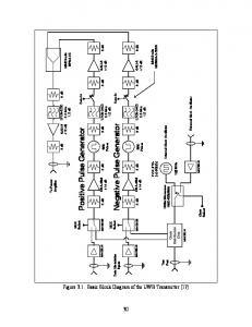
A. UWB localization simulator An Ultra-Wideband localization simulator is implemented in Matlab/Simulink. It consists of three main blocks as depicted in fig. 1. The transmitter architecture is based on the pulse generator developed by IHP [25]. The transmitter creates a bi-phase pulse train with rectangular pulses of width tp, which are low-pass filtered and then modulated by a carrier frequency fc. The pulse train PN of length lPN and pulse repetition frequency PRF has good autocorrelation properties, and the low pass filter is implemented as a 3rd order Bessel filter with a cut-off frequency of fLP. As a result, the transmitter can flexibly be adapted to regulatory requirements by changing carrier frequency and pulse width (via fLP). The channel block accepts different channel models, which are used for filtering the transmitted signals. Two channel models are available that are applicable for an Ultra-Wideband indoor environment. The first
Channel fc
fLP
θcs =
(8)
where τ RMS (δds , dˆn ) is evaluated using the range estimate dˆn at time step n. The threshold Θds,n is only updated if the current condition has the delay spread τ min = τRMS (δds ,1) evaluated at 1m, i.e. is LOS with a very high probability. For example, for a noise exclusion threshold δds of 5dB, τ min = 2nsec. The noise exclusion threshold should be set as high as the SNR allows. It should be noted however that the delay spread can also depend on the environment itself, e.g. room size, wall conditions. It is obvious that such parameters cannot be included in the threshold as they would require precise environment data, which are unrealistic to acquire and maintain.
tp
paths are detected and normalized:
LOS or NLOS Channel model
Receiver tUWB
Virtual trajectory
AWGN
fc±fLP
PN
Fig. 1. Block diagram of the UWB localization simulator.
x-Correlator
Path detector
one is developed by the IEEE 802.15.4a task group, which principle interest lies in the standardization of communications and high precision ranging. It provides purely statistical models in the frequency range from 2 to 10GHz covering office and industrial environments for LOS and NLOS conditions [26]. The second model is based on the European IST project Whyless.com. It covers the frequency range from 1 to 11GHz and combines a statistical approach to model multipath and a simple quasi-deterministic method to model strong individual echoes. The result is a space-variant channel model with spatial evolution of channel impulse responses [27]. This property is quite important for localization simulation, since reflections can heavily influence the range estimation. The respective channel model is fed with varying transmitter positions out of a virtual trajectory and a fixed receiver position. The virtual trajectory represents a typical itinerary of persons or objects within a room and is based on the random waypoint model, which is used in many research fields as a representation for the movement of persons and objects [28]. The generation of the virtual trajectory is as follows: – The object is placed at the initial position, – randomly draws a new 3D position within the given area [xmax,ymax,zmax], a velocity within the interval [vmin,vmax] and a pause time within the interval [pmin,pmax], – walks with update interval tUWB to the new location and pauses using the drawn parameters. In addition, each created transmitter position is assigned, whether it should have an LOS or NLOS channel with respect to the receiver. To simulate a realistic alternation between LOS and NLOS, each channel condition is randomly drawn to remain for a distance within the interval [dmin,dmax]. The receiver is implemented in an optimal matched filter architecture and the time of arrival is estimated using the FirstMax algorithm, which searches the region before the maximum for other paths, whose energy is a certain percentage lower than that of the maximum [1, 29]. This method is able to detect the correct direct path under NDDP channel conditions. The search region is set to 50m before and the threshold to –1.5dB of the maximum, which seams to be reasonable in an indoor environment. The adjusted parameters for the simulation are shown in Table I. The transmitter power was chosen such that it fits the draft European regulation for location tracking equipment for indoor environments [30]. It has approximately a 10dB bandwidth of 2GHz. An additive noise floor of 10dB above thermal noise seems to be realistic for such broadband systems. Further, the parameters for the random waypoint model are chosen to represent realistic movement of persons and objects in an industrial or office environment. The sample rate fs is adapted to oversample approximately
eight times the maximal occurring frequency. A virtual trajectory with 10000 positions was generated and fed into the UWB simulator resulting in 10000 channel impulse and range estimates per channel model (IEEE office, IEEE industrial, Whyless office). Afterwards, the detection algorithms are used to decide LOS or NLOS. B. UWB measurements In addition to the simulations measurements with a self-developed UWB localization system were performed. The system has been described and tested in [20, 31]. The parameters for the signal processing namely search region and FirstMax threshold are set equally as for the simulation to achieve comparable results. Two different environments have been chosen. The first one is a big office room at the IKT of size 8x12x2.6m. A person holding the mobile unit walked randomly through the room. While walking the channel was arbitrarily chosen to be covered by the person’s body, hence resulting in an NLOS condition. 1000 measurements with approx. 50% NLOS were recorded with the UWB prototype system. The second environment is an industrial storage environment as described in [20] with maximal distances between mobile unit and base stations of 17m. The NLOS condition was achieved by placing an absorbing wall in the direct line of sight between the two antennas. Here, 200 measurements with 50% NLOS were recorded. After recording the data and subsequent signal processing the described detection algorithms are used to decide LOS or NLOS.
TABLE I PARAMETERS OF THE UWB LOCALIZATION SIMULATOR PARAMETER
VALUE
UNIT
CHANNEL MODELS
WHYLESS OFFICE IEEE INDUSTRIAL IEEE OFFICE
fc.
7.55
GHz
tp
500
ps
PRF
3.2
MHz
fLP
1000
MHz
tUWB
0.1
Hz
[pmin,pmax]
[0.2,5]
sec
[vmin,vmax]
[0.2,1.5]
m/sec
[dmin,dmax]
[1,10]
m
[xmax,ymax,zmax]
[28,10,2.6]
m
fs
80
GHz
A. Running variance As it can be seen from Table II the running variance has problems to properly detect especially NLOS conditions. As stated in paragraph III.A this is due to both latency in the detection and constant offsets in the range estimates. It turns out that the impact of the offset effect is the major drawback of the running variance method. This can be observed with the measurements as well as the Whyless channel model. This seams to be realistic, since geometric characteristics are not modeled in the IEEE channel model. Hence, influences based on this cannot occur. Note, the latency problem could be reduced with a high update rate of a localization system; however, the offset effect is an inherent property of certain NLOS environments. The update interval of the IKT office measurements is set to tUWB = 0.3 sec , for all others 0.1sec. B. Confidence metric The confidence metric seems to perform quite well for detecting both LOS and NLOS with the proposed distance dependent threshold. As the analysis is purely based on one single measurement no latency is introduced. However, the major drawback of this method lies in the necessity to determine the two parameters of the threshold (θmax , dmax ), which should equal for a given localization system setup. The calculated parameter pairs for the simulations are (4.4dB,28m), for the office measurements (3.5dB,10.2m), and for the industrial measurements (5.2dB,14.4m). The dissimilar parameter set for the measurements could be explained with a varying template power between the two setups. However, no further investigation was undertaken to prove this assumption. C. Delay spread As stated in [26], the distance dependence of the delay spread is neglected in the IEEE channel models. Hence, the distance dependent threshold cannot be applied. Therefore, the threshold was set to 1.5nsec for IEEE office and 20nsec for IEEE industrial with a noise exclusion threshold of δds = 10dB respectively. From the results of the Whyless channel model it does not seem to be clear if the distance dependence is modeled. Therefore, the threshold is also set fix to 1.5nsec with δds = 10dB. Looking at the measurements the delay spread seems to work acceptable as an NLOS detection technique. However, it is difficult to interpret if the results of the simulations support this outcome. Although the results
D. Change of SNR The change of SNR method shows good performance except for the IEEE channel models. Whereas this could be interpreted as a problem of this method, the authors however see the reason in the implementation of the IEEE channel models. Since no relation exists between subsequent drawings of the channel impulse response, the impact of major reflecting echoes at a certain location is not modeled. As a consequence reception power varies independently of the preceding value and leads to unrealistic changes in SNR. This is backed by observable changes in reception power of up to 5dB even in LOS situations, which seems to be unlikely for such broadband UWB systems [32]. The functionality and simplicity of the change of SNR method can therefore still be assumed.
TABLE II QUALITY OF NLOS DETECTION ALGORITHMS: THE FIRST THREE LINES SHOW THE QUALITIES OF THE NLOS DETECTION METHODS OF EACH CHANNEL MODEL EVALUATED WITH THE UWB SIMULATOR. THE LAST TWO LINES SHOW THE QUALITIES OF THE METHODS EVALUATED WITH THE UWB MEASUREMENT SYSTEM.
CHANGE OF SNR [%]
Table II compares the performance of the algorithms, where the quality of NLOS detection is calculated as the percentage of detected NLOS of all NLOS positions (P(NLOS|NLOS)). LOS detection quality is computed accordingly (P(LOS|LOS)).
of the IEEE industrial and Whyless office simulation are promising, they are based on thresholds that are determined afterwards based on the histogram of the delay spread calculation. In addition, the IEEE office model does not perform well due to a similar channel envelope for LOS and NLOS.
DELAY SPREAD [%]
DISCUSSION
CONFIDENCE METRIC [%]
AND
RUNNING VARIANCE [%]
V. RESULTS
IEEE
P(NLOS|NLOS)
29.8
99.8
70.3
67.1
OFFICE
P(LOS|LOS)
84.1
99.9
75.1*
61.5
IEEE
P(NLOS|NLOS)
98.9
93.5
99.9
94.3
INDUSTRIAL
P(LOS|LOS)
80.4
93.0
99.2*
60.3
WHYLESS
P(NLOS|NLOS)
44.3
100.0
100.0
99.7
OFFICE
P(LOS|LOS)
91.4
100.0
99.6*
100.0
SIMULATIONS
MEASUREMENTS IKT OFFICE
P(NLOS|NLOS)
79.7
98.2
97.8
93.8
P(LOS|LOS)
94.3
95.1
95.5
97.0
72.0
100.0
88.0
100.0
84.4
100.0
96.0
100.0
IKT INDUS- P(NLOS|NLOS) TRIAL P(LOS|LOS)
* NOT EVALUATED WITH THE PROPOSED THRESHOLD
VI. CONCLUSION A simulative and real-world comparison of four NLOS detection methods has been conducted. The running variance essentially fails due to the occurrence of constant offsets in range estimation during NLOS. The good performance of the confidence metric must be related to the necessity that a predefined threshold could not be found, which leads to the upfront evaluation of two parameters with the localization system. Further, the results of detecting NLOS based on the delay spread are difficult to interpret. Whereas the measurements show an adequate recognition, simplifications of the channel models lead to a malfunction of the proposed adaptive threshold. Finally, the newly proposed change of SNR method performs well for both the measurements and the Whyless channel model. It could be shown that the failure of detection with the IEEE models is due to the implementation character of the respective models. REFERENCES [1] J.-Y. Lee and R. A. Scholtz, "Ranging in a dense multipath environment using an UWB radio link," Selected Areas in Communications, IEEE Journal on, vol. 20, pp. 1677-1683, 2002. [2] S. Venkatraman, J. Caffery, Jr., and H.-R. You, "Location using LOS range estimation in NLOS environments," IEEE 55th Vehicular Technology Conference, VTC Spring, 2002, pp. 856-860 vol.2. [3] K. Pahlavan, P. Krishnamurthy, and A. Beneat, "Wideband radio propagation modeling for indoor geolocation applications," Communications Magazine, IEEE, vol. 36, pp. 60-65, 1998. [4] J. Borras, P. Hatrack, and N. B. Mandayam, "Decision theoretic framework for NLOS identification," 48th IEEE Vehicular Technology Conference, Ottawa, Canada, 1998, pp. 1583-1587 vol.2. [5] S. Gezici, H. Kobayashi, and H. V. Poor, "Nonparametric nonline-ofsight identification," IEEE 58th Vehicular Technology Conference (VTC 2003-Fall), Orlando, USA, 2003, pp. 2544-2548 Vol.4. [6] S. Venkatraman and J. Caffery, Jr., "Statistical approach to non-lineof-sight BS identification," 5th International Symposium on Wireless Personal Multimedia Communications, Honolulu, Hawaii, 2002, pp. 296-300 vol.1. [7] M. P. Wylie and J. Holtzman, "The non-line of sight problem in mobile location estimation," 5th IEEE International Conference on Universal Personal Communications, Cambridge, MA, USA, 1996, pp. 827-831 vol.2. [8] J. S. Al-Jazzar and J. Caffery, "New Algorithms for NLOS Identification," IST Mobile and Wireless Commun. Summit 2005, Dresden, Germany, 2005. [9] I. Oppermann, M. Hämäläinen, and J. Iinatti, UWB: Theory and Applications. UK: Wiley, 2004. [10] J. Vidal, A. Pagès, O. Muñoz, M. Cabrera, M. Nájar, and M. A. Lagunas, "Overview of UMTS User Location Possibilities and Limitations," Deliverable IST SATURN D231 2001. [11] H. Shimizu, H. Masui, M. Ishii, and K. Sakawa, "LOS and NLOS pathloss and delay characteristics at 3.35 GHz in a residential environment," IEEE Antennas and Propagation Society International Symposium, 2000, pp. 1142-1145 vol.2. [12] A. Lakhzouri, E. S. Lohan, R. Hamila, and M. Renfors, "Extended Kalman Filter Channel Estimation for Line-of-Sight Detection in WCDMA Mobile Positioning," EURASIP Journal on Applied Signal Processing, vol. 13, pp. 1268–1278, 2003. [13] M. Tüchler and A. Huber, "An Improved Algorithm for UWB-Based Positioning in a Multi-Path Environment," International Zurich Seminar on Communications, Zurich, Switzerland, 2006.
[14] R. Casas, A. Marco, J. J. Guerrero, and J. Falcó, "Robust Estimator for Non-Line-of-Sight Error Mitigation in Indoor Localization," EURASIP Journal on Applied Signal Processing, vol. 2006, pp. Article ID 43429, 8 pages, 2006. [15] J. Yung-Hoon, L. Joon-Yong, H. Dong-Heon, and K. Shin-Hoo, "Accuracy Enhancement for UWB Indoor Positioning Using Ray Tracing," Position, Location, And Navigation Symposium (PLANS), San Diego, 2006, pp. 565-568. [16] D. E. Gustafson, J. M. Elwell, and J. A. Soltz, "Innovative Indoor Geolocation Using RF Multipath Diversity," IEEE/ION Position, Location, And Navigation Symposium, San Diego, USA, 2006, pp. 904912. [17] E. Medina and M. Najar, "High resolution location in ultra wideband communications systems," Second International Workshop Networking with Ultra Wide Band, Rome, Italy, 2005, pp. 40-44. [18] D. Jourdan, J. Deyst, M. Win, and N. Roy, "Monte-Carlo Localization in Dense Multipath Environments Using UWB Ranging," IEEE International Conference on Ultra-Wideband, Zürich, 2005. [19] B. Denis, L. Ouvry, B. Uguen, and F. Tchoffo-Talom, "Advanced Bayesian Filtering Techniques for UWB Tracking Systems in Indoor Environments," IEEE International Conference on Ultra-Wideband, Zürich, 2005. [20] S. Galler, J. Schroeder, K. Kyamakya, and K. Jobmann, "Analysis and practical comparison of Wireless LAN and Ultra-Wideband technologies for advanced localization," accepted at IEEE/ION Position, Location and Navigation Symposium (PLANS 2006), San Diego, USA, 2006, pp. 198-203. [21] T. S. Rappaport, Wireless communications : principles and practice, 2nd ed ed. Upper Saddle River, NJ: Prentice Hall PTR, 2002. [22] R. J. M. Cramer, R. A. Scholtz, and M. Z. Win, "Evaluation of an ultra-wide-band propagation channel," Antennas and Propagation, IEEE Transactions on, vol. 50, pp. 561-570, 2002. [23] J. A. Dabin, N. Nan, A. M. Haimovich, E. Niver, and H. Grebel, "The effects of antenna directivity on path loss and multipath propagation in UWB indoor wireless channels," IEEE Conference on Ultra Wideband Systems and Technologies, Reston, VA, USA, 2003, pp. 305-309. [24] S. S. Ghassemzadeh, R. Jana, C. W. Rice, W. Turin, and V. Tarokh, "A statistical path loss model for in-home UWB channels," IEEE Conference on Ultra Wideband Systems and Technologies, 2002, pp. 59-64. [25] X. Fan, G. Fischer, and B. Dietrich, "An integrated 3.1-5.1 GHz pulse generator for ultra-wideband wireless localization systems," Advances in Radio Science, vol. 4, pp. 247-250, 2006. [26] A. F. Molisch, K. Balakrishnan, D. Cassioli, C.-C. Chong, S. Emami, A. Fort, J. Karedal, J. Kunisch, H. Schantz, U. Schuster, and K. Siwiak, "IEEE 802.15.4a channel model - final report," IEEE 2005. [27] J. Kunisch and J. Pamp, "An ultra-wideband space-variant multipath indoor radio channel model," IEEE Conference on Ultra Wideband Systems and Technologies (UWBST), Reston, USA, 2003, pp. 290294. [28] D. B. Johnson and D. A. Maltz, "Dynamic Source Routing in Ad Hoc Wireless Networks," in Mobile Computing, T. Imielinski and H. Korth, Eds.: Kluwer Academic Publishers, 1996. [29] S. Galler, "Entwurf und Aufbau eines Systems zur Ortung von Personen auf Bühnen," in Fachbereich Elektrotechnik und Informationstechnik. Hannover: University of Hannover and Sennheiser electronic GmbH & Co. KG, 2003. [30] ETSI, "Electromagnetic compatibility and Radio spectrum Matters (ERM); Short Range Devices (SRD) using Ultra WideBand (UWB) technology; Location Tracking equipment operating in the frequency range from 6 GHz to 9 GHz;Part 1: Technical characteristics and test methods, Draft ETSI EN 302 500-1 V1.1.1 (2006-05)," Sophia Antipolis, France 2006. [31] J. Schroeder, S. Galler, and K. Kyamakya, "A Low-Cost Experimental Ultra-Wideband Positioning System," Proceedings of IEEE International Conference on Ultra-Wideband, Zürich, Switzerland, 2005, pp. 632-637. [32] J. Romme and B. Kull, "On the relation between bandwidth and robustness of indoor UWB communication," Ultra Wideband Systems and Technologies, 2003 IEEE Conference on, 2003, pp. 255-259.