NoC designs, a complete NoC synthesis flow and detailed scalability analysis. ... Relevant research in application-specific custom topology design has been ...
NoC Design and Implementation in 65nm Technology
Antonio Pullini1 , Federico Angiolini2 , Paolo Meloni3 , David Atienza4,5 , Srinivasan Murali6 , Luigi Raffo3 , Giovanni De Micheli4 , and Luca Benini2 1 2
Politecnico di Torino, Torino, Italy
DEIS, University of Bologna, Bologna, Italy
3
DIEE, University of Cagliari, Cagliari, Italy 4
5
LSI, EPFL, Lausanne, Switzerland DACYA, Complutense University, Madrid, Spain 6
CSL, Stanford University, California, USA
Abstract As embedded computing evolves towards ever more powerful architectures, the challenge of properly interconnecting large numbers of on-chip computation blocks is becoming prominent. Networks-on-Chip (NoCs) have been proposed as a scalable solution to both physical design issues and increasing bandwidth demands. However, this claim has not been fully validated yet, since the design properties and tradeoffs of NoCs have not been studied in detail below the 100 nm threshold. This work is aimed at shedding light on the opportunities and challenges, both expected and unexpected, of NoC design in nanometer CMOS. We present fully working 65 nm NoC designs, a complete NoC synthesis flow and detailed scalability analysis.
1
Introduction
As steady progress is being made in the miniaturization of chip features, embedded systems are quickly evolving towards complex devices, including a large set of computation engines, dedicated accelerators, input/output controllers and multiple memory buffers. MultiProcessor System-onChip (MPSoC) is a commonly used term to describe the resulting outcome. However, this feature- and performanceoriented evolution is not devoid of significant challenges, including mastering the increasing design complexity and minimizing power consumption. Moreover, miniaturization itself is bringing its own set of design issues at the physical level, originated primarily by an increasing ratio of wire vs. logic propagation delay.
One of the most critical areas of MPSoC design is the interconnect subsystem, due to architectural and physical scalability concerns. Traditional shared bus interconnects are relatively easy to design, but do not scale well. Thus, evolutions have been conceived both from the protocol (e.g. outstanding transactions with out-of-order delivery) and the topology (e.g. bridges, crossbars) points of view. Nevertheless, scalability is still suboptimal, as protocol improvements still hit a bandwidth limit due to the available physical resources, and topological extensions require the use of bridges (i.e. multiple buses or “spaghetti-like” design)) or large area overheads in routing structures (i.e. using crossbars). Networks-on-Chip (NoCs) have been suggested as a promising solution to the scalability problem [5]. By bringing packet-based communication paradigms to the on-chip domain, NoCs address many of the issues of interconnect fabric design. Wire lengths can be controlled by matching network topology with physical constraints and bandwidth can be boosted by increasing the number of links and switches. Furthermore, compared to irregular, bridge-based assemblies of clusters of processing elements, NoCs also help in tackling design complexity issues [21, 6]. While these key advantages of NoCs have been largely accepted nowadays, the practical implementation of NoCs in very deep submicron technology, below the 100 nm threshold, is a very open challenge. The crucial issue is again related to wiring. Even if capacitive loads and propagation delays can be controlled much better than in shared buses, issues such as wiring congestion, link power consumption, and the need for placement-aware logic synthesis still have to be explored to assess the feasibility of NoCs in forthcoming technology nodes. This paper presents a detailed description of a 65 nm
NoC design flow and outlines some of the tradeoffs that a next-generation back-end implies. In this work we explore link performance, placement issues, scaling results in shifting from 90 nm to 65 nm technologies, and the degrees of freedom allowed by the availability of multiple libraries (with different power/performance tradeoffs) at the same technology node. The remainder of the paper is organized as follows. In Section 2 we overview previous work in the field on onchip interconnects in general and, more particularly, focus on NoC synthesis and topology design and layout. Then, in Section 3 we introduce our NoC design flow, spanning from the target application task graph to the placement&routing steps. Next, in Section 4 we analyze and discuss the major properties of the 65 nm NoC design flow, while in Section 5 we show performance, area and power comparisons. Finally, in Section 6 we draw our conclusions and propose future extensions.
2
Related Work
The problem of high-performance or low-power synthesis of on-chip interconnects based on the bus paradigm has been studied extensively in the literature [30, 12, 31]. The use of point-to-point links and bus design using floorplan feedback has been also explored [17]. Recent research has focused on efficient synthesis methods for NoC-based interconnects and comparisons with bus-based SoCs [18, 24, 2]. Relevant research in application-specific custom topology design has been proposed in earlier works on NoC design for well-behaved or regular traffics [32, 16, 9]. Floorplanning estimations and analytical models have been employed during the topology design process to obtain area and wirelength estimates [34, 24], but these works are limited to libraries of standard topologies. A physical planner has been used to focus on minimizing power consumption on the links of NoC topologies [1]. However, this method does not consider the area and power consumption of switches in the design. In [27], a flow that addresses the problem of full custom NoC topology design with early floorplan estimation is proposed. However, even though these works have considered the various problems of NoCs synthesis at the physical level, none of them has studied and covered extensively the possible consequences of different process technology nodes on complete NoC-based interconnects, as we present in this paper. In addition, methods to build area and power models for various NoC components have been developed to enable system-level exploration of SoCs using NoC interconnects [4, 14, 29, 39]. However, the existing area-power models of the NoC components, such as switches or network interfaces, were not targeting the 65 nm manufacturing technology and may need to be revised with the latest back-end tools to properly capture model requirements, as we illustrate in our results. At a higher level of abstraction, different methods have been proposed to analyze traffic information and obtain models that can be utilized as inputs to bus and NoC design methodologies [22, 26]. These approaches are complementary to this work. In addition, the problem of supporting multiple applications has been studied [3, 25]. Also, methodologies that unify resource reservation, mapping and routing in NoC designs have presented [15, 23]. However, these works do not fully explore the topology design process.
Important research contributions have been presented on automatic code generation of NoC topologies for simulation [40, 33, 10] and synthesis [20, 19]. These works complement the presented one, as their inputs are typically NoC designed topologies and even enable the use of postsynthesis timing libraries in their simulation models. A very interesting study on the impact of technology scaling on the energy efficiency of standard topologies (such as meshes, tori and their variants) has been presented in [13]. Our work differs from this research in two ways: first, we consider the design of platform-specific NoC topologies and architectures. Second, we use a complete design flow that is integrated with standard industrial toolchains to perform accurate physical implementations of the NoCs.
3
NoC Design Flow
An overview of our proposed complete flow for designing NoCs for MPSoCs is presented in Figure 1. This flow comprises several tools that are integrated together. First, SunFloor, which automates the front-end process of NoC design. Second, ×pipesCompiler, which automates the architecture generation phase (leveraging the ×pipes library of NoC components). Finally, several industrial tools that automate the back-end processes, i.e. the logic synthesis and physical design.
3.1
SunFloor
The SunFloor tool, presented in [27], is used to synthesize the best custom NoC topology for a given MPSoC platform, which satisfies the communication constraints of the design. The tool uses as inputs the communication characteristics of the applications, as well as the design objectives and constraints. Then, it generates the optimal network topology, i.e. the number and size of needed switches, the connectivity between them and the paths used by the different traffic flows to route data across the switches. To this end, the tool includes several important features: • It supports multiple optimization objectives, such as minimizing power consumption and maximizing performance. • It synthesizes topologies that are free from messageand routing-dependent deadlocks. • It closes the gap between the architectural and physical design phases by performing a floorplan-aware synthesis process. • It automatically sets the NoC architectural parameters, like the frequency of operation.
3.2
SunFloor Area and Power Libraries
In order to synthesize efficient NoC topologies, the SunFloor tool needs accurate area and power models describing the NoC switches and links [27]. The models used need to be parametric in various aspects, such as the switch cardinality. As it can be seen from Figure 1, our toolchain not only supports a front-end to back-end flow, but also has feedback from the back-end physical design process to the front-end phase.
Figure 1. Our proposed complete NoC design flow for MPSoCs At the beginning of the NoC design process, preliminary syntheses (including placement&routing) of the switches are carried out, varying several architectural parameters, namely, the number of input and output ports, the depth of buffers and the flit width. The same process is performed for NoC links, varying their length and flit width. Then, from the layout implementations, the area, power and delay values are obtained for the different configurations. The results are stored as tables and utilized by the SunFloor tool. The area, power and frequency values for some example switch configurations are shown later in Figure 4. The power consumption of different NoC links is presented in Figure 3.
3.3
The ×pipes NoC Library
In the next phase of the design flow, the RTL-level SystemC code of the switches, network interfaces and links for the designed topology is automatically generated. To this end, we use ×pipes [7], a library of soft macros for the network components, and the associated tool ×pipesCompiler [20], which configures and interconnects the network elements and the cores. The RTL-level SystemC representation of ×pipes can be fully simulated within a cycle-accurate virtual platform, to assess and optimize its performance and for validation purposes. ×pipes includes three elementary components: switches, Network Interfaces (NIs) and links, which are highly configurable to be able to build any NoC topology. Switches can be instantiated with any number of input and output ports, and include FIFOs at each port to implement output buffering. The switches include logic to implement an ACK/NACK flow control policy [11], and handle priorities among incoming packets that demand the same physical link. NIs are instantiated to enable the communication of any external component to the NoC (e.g. processing
cores or memories) using the Open Core Protocol (OCP) v2.0 [28]. The NIs are in charge of converting the OCP transactions into packets and then into sequences of bits or FLow control unITS (flits), which are the basic transmission element, thus limiting the number of physical wires required for each link. Two different types of NIs can be instantiated in ×pipes, according to the role of the connected component, namely initiator and target. For master/slave cores, two NIs (one of each type) need to be instantiated. ×pipes uses source-based routing. Hence, each NI includes a Look-Up Table (LUT) that holds the paths to reach the other cores with which communication is expected to happen. The connectivity of each core to other cores, and therefore its associated LUT, is defined in the previous phase of our NoC synthesis process (see Section 3.1). ×pipes supports link pipelining, where logical buffers are interleaved along links. This feature reduces signal propagation delays, and as we illustrate in our analysis (Section 4.2) and results (Section 5), it is a very relevant element in latest technology nodes. ×pipes is a fully synchronous NoC. The main reason for this choice is to avoid the design flow complexity, the hardware cost and the performance overhead associated with clock domain crossing. However, the NIs feature two different clock inputs on the NoC side and on the OCP side; the only constraint is that the ×pipes frequency should be an integer multiple of the frequency of the OCP core. This arrangement has minimal hardware and performance penalties, while still providing flexible support for attaching to the NoC cores running at many different possible speeds.
3.4
Flow Back-End
In the proposed NoC design and synthesis framework for ×pipes we provide a complete back-end flow based on
standard cell synthesis. First, we perform the logic synthesis step, by utilizing standard Synopsys tools. The details of this part of the flow will be given in Section 4.1. We follow this procedure by using 90 and 65 nm technology libraries by a partner foundry, tuned for different performance/power tradeoffs, with different threshold and supply voltages. While full custom design would certainly improve results, it would also greatly decrease flexibility and increase design time.
Figure 2. The synthesis flow for ×pipes During synthesis, we can optionally instruct the logic synthesis tools to save power when buffers are inactive by applying clock gating to NoC blocks. The gating logic can be instantiated only for sequential cells which feature an input enable pin, which are a large majority of the datapath flip-flops of ×pipes. We subsequently perform the detailed placement&routing step within Synopsys Astro [35]. Two of the main placement strategies commonly available within industrial tools are virtual flat and soft macros. In the former option, the tool is fed with the complete design, and albeit placement guidelines can be given, the tool is allowed to modify the global floorplan. This theoretically allows for maximum optimization and better handling of design violations; unfortunately, for a design as large as a whole NoC-based chip, we found it to be extremely demanding on system resources (more than 5 GB of RAM were needed by the placement process, and runtimes were unacceptable). The soft macro alternative is based on rigid fences which separate floorplan areas. Each module of the design is assigned to one such area; the tool is able to freely perform placement operations within such modules and areas, but it is not allowed to trespass fences. We resort to a mix of the two strategies for optimal results. First, we feed Astro with a rough floorplan, generated either manually or by SunFloor. This floorplan contains hard macros and soft macros, separated by fences. The hard macros represent IP cores and memories, and are modeled as black boxes. Hard macros are defined with a Library Exchange Format (LEF) file and a Verilog Interface Logical Model, and obstruct an area of our choice. These boxes also obstruct some of the metal layers laying directly above; the exact number of obstructed levels is configurable, depending on how many metal layers the IP cores are supposed to require and on whether we want to allow over-the-cell rout-
ing for the NoC wires vs. between-the-cell. Soft macros enclose the modules of ×pipes; by constraining the placement tool to operate on one tile at a time, faster runtimes can be achieved. For proper results, however, it becomes necessary to specify rough timing constraints at the soft macro boundaries; we achieve this by pre-characterization of the links (please see Section 4.2 below). The next step in the flow is clock tree insertion. While a separate clock tree could be added to each soft macro, it would be difficult to control the skew when joining the trees together and attaching them to a single clock source. Therefore, for this step, we shift up again in the design hierarchy, and operate at a global level. The clock tree is added by leveraging clock borrowing algorithms in the tools; in other words, clock skews are exploited to accommodate the delay properties of the circuits, by supplying wider clock periods where the logic paths are most critical. Once the clock tree has been generated, its wires are kept untouched within the tool, to prevent further skews from appearing. At this point, the power supply nets are added. To improve supply stability, we choose the power grid scheme instead of the traditional power ring; power nets are distributed from the topmost metal layers of the chip, instead of from a ring around the die. This minimizes IR drops (voltage drops and fluctuations due to resistive effects in the supply networks and to the current draw). After the power nets have been routed, the tool begins to route the logic wires. After an initial mapping, search&repair loops are executed to fix any violations. As a final step, post-routing optimizations are performed. This stage includes crosstalk minimization, antenna effect minimization, and insertion of filler cells. Finally, a signoff procedure can be run by using Synopsys PrimeTime [38] to accurately validate the timing properties of the resulting design.
3.5
Post-Layout Analysis
Post-layout verification and power estimation is achieved as follows. First, the HDL netlist representing the final placed&routed topology, including accurate delay models, is simulated by injecting functional traffic through the OCP ports of the NIs. This simulation is aimed both at verifying functionality of the placed fabric and at collecting a switching activity report. At this point, accurate wire capacitance and resistance information, as back-annotated from the placed&routed layout, is combined with the switching activity report using Synopsys PrimePower [37]. The output is a layout-aware power/energy estimation of the simulation.
4
Wire Design in 65 nm Technologies
As mentioned above, wires are a very important element in sub-100 nm technologies. Our experience with a 65 nm design flow has shown that wires are critical both within NoC modules and for inter-module links. The following subsections will briefly describe our findings at both levels.
4.1
Placement-Aware Logic Synthesis
The traditional flow for standard cell design features logic synthesis and placement as two clearly decoupled stages. While our in-house experience [2] shows that this
flow achieved reasonable enough results for 130 nm NoC design, we have found this assumption to be substantially inadequate at the 65 nm node. The origin of the problem lies in the same concept that enables the splitting of the two steps, namely, wireload models. Wireload models are pre-characterized equations, supplied within technology libraries, that attempt to predict the capacitive load that a gate will have to drive based on its fan-out alone. A gate driving a fan-out of two other gates is very likely to be part of a local circuit. Thus, its capacitive load is little more than the input capacitance of the two downstream gates. A gate with a fan-out of one thousand is likely to be the driver of a global network. Therefore, some extra capacitance is expected due to the long wires needed to carry the signal around. This assumption works very well as long as wire loads do not become too large. Otherwise, the characterization of wireload models becomes very complex, and the prediction inaccuracies become critical. In our 65 nm test explorations, we have found unacceptable performance degradation due to inaccuracies in wireload estimation. Even when synthesizing single NoC modules (i.e., even without considering long links), after the logic synthesis step, tools were expecting some target frequency to be reachable. However, after the placement phase, the results were up to 30% worse. Unfortunately, traditional placement tools are not able to deeply modify the netlists they are given as an input. In general, they can only insert additional buffering to account for unexpected loads on few selected wires. Therefore, if the input netlist is fundamentally off the mark due to erroneous wireload expectations, not only a performance loss is certain, but the placement runtime skyrockets. To address this issue we leverage placement-aware logic synthesis tools, such as Synopsys Physical Compiler [36]. In this type of flow, after a very quick initial logic synthesis based on wireload models, the tool internally attempts a coarse placement of the current netlist, and also keeps optimizing the netlist based on the expected placement and the wire loads it implies. The final resulting netlist already considers placement-related effects. Therefore, after this netlist is fed to the actual placement tool, performance results do not incur major penalties. In addition, we have found other wiring- and placementrelated problems within soft macros due to congestion. In our test designs, placements tools performed poorly both when modules had to be placed within too small and too wide fences. While the former case is clearly understandable, we attribute the unexpected latter effect to the placement tool heuristics, which are probably performing worse when the solution space becomes very large. Thus, the problem must be solved by proper tuning of the spacing among the soft macro fences and, consequently, accurate area models of the NoC modules are required to avoid very time-consuming manual interventions in the synthesis process.
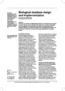
sumption. The reason is that when links are pushed for high performance, back-end tools automatically insert large amounts of buffering gates, increasing the energy cost of the links. In our validation experiments, the feasibility threshold of high-frequency or very long links was in some cases set by the inability to decrease delay further and in some cases by crosstalk concerns. In other words, the added buffers would sometimes be too large to be safely deployed. Another extremely important dependency we noticed was on the specific technology library in use. As Section 5 shows, especially at the 65 nm node, a single “technology library” no longer exists for standard cell design. In fact, manufacturing technologies are spreading across a variety of libraries optimized for specific uses, such as low power or high performance, with several intermediate levels featuring for example different threshold voltage values. In this case, if very low power libraries are used, the size and speed of the buffers that can be interleaved along wires becomes dramatically inferior, which results in much tighter constraints on frequency of operation or length. Figure 3(a) reports power consumption for a 65 nm low power library tuned for a low threshold voltage (called LP-LVT in the following), and therefore for a power/performance tradeoff. Figure 3(b) is based on a 65 nm low power library tuned for a high threshold voltage (LP-HVT), and therefore for minimum power consumption. As can be seen, the LP-HVT library is substantially more power effective than the LP-LVT library, but puts much tighter constraints on link feasibility. Link repeaters can be used to tackle this issue. We define repeaters as clocked registers along links. By providing one or more extra clock periods to traverse long distances, they solve the link infeasibility problem at a much lower cost than that of deploying whole NoC switches in the middle of the links. In some cases, repeaters may even produce more power-effective solutions than regular wire buffering along particularly critical links, but at a performance cost (i.e., one extra cycle of latency). In all cases, the NoC flow control protocol must be designed in such a way as to enable a transparent insertion of the repeaters. Alternatively, repeaters must contain extra logic to properly handle the flow control handshake signals. In our design flow we include support for pipelined links at all levels of abstraction, starting from the high-level SunFloor tool down to final layout tools. In fact, in our earlier work [27], the topologies synthesized by SunFloor required that the links could be traversed in a single clock cycle. In this work, we have removed this assumption by including in SunFloor the pre-characterization of link delay information. Therefore, Sunfloor automatically pipelines long links in the design, based on the targeted frequency of operation. When a link is pipelined and its latency increases, SunFloor considers this information to determine the average latency of the NoC and, therefore, takes it into account in its cost metrics.
4.2
5
Link Delay and Link Power
In order to assess the impact of global wires, we have studied 65 nm NoC links in isolation from the NoC modules. An overview of some of our analyses can be found in Figure 3. Our results show that several factors have to be considered in link design. Two obvious factors are link length and desired clock frequency. Short links or links clocked at a very slow frequency do not pose problems. However, as either length or target frequency are increased, an undesired effect appears in the form of high power con-
5.1
Experimental Results Technology Scaling from 90 to 65 nm
In our first set of results (see Figure 4) we have studied the effect of scaling when the ×pipes switches are synthesized in four different libraries, namely, two 65 nm and two 90 nm ones, tuned for different power/performance tradeoffs (LP-LVT and LP-HVT). In these experiments, switches were fully placed&routed, including the addition of a clock
45 40 35 30 25 Normalized power 20 15 9,0
10
5,0
5
2,5
0
Link length (mm)
1,5 250 500 750 1000 1250 1500 1750 2000 Clock frequency (MHz)
0,5
(a) performance/power oriented 65 nm library (LP-LVT)
(a) power
6,0
5,0
4,0
Normalized power 3,0
2,0 9,0 1,0
5,0 2,5
0,0
1,5 250 500 750 1000 1250 1500 1750 2000 Clock frequency (MHz)
Link length (mm)
0,5
(b) very low-power 65 nm library (LP-HVT)
(b) operating frequency
Figure 3. Power consumption of 38-bit links of varying lengths at different operating frequencies. Values normalized to shortest link at slowest frequency for confidentiality reasons. Missing columns represent infeasible length/frequency combinations.
tree. Then, syntheses were tuned for the maximum operating frequency. To this end, we disabled the clock gating option. As can be seen in the results, 65 nm libraries provide large opportunities for improvement over their 90 nm predecessors. In fact, we have observed power consumptions which are about 50% lower (up to 75% lower when comparing the LP-HVT versions), and area savings of 4050%. It is also important to observe the large difference in synthesis results among two different libraries at the same technology node. For the 65 nm case, the LP-HVT library is consuming one order of magnitude less power than the LP-LVT variant. In addition, our results indicate that this performance spread is increased compared to the 90 nm libraries. For example, by observing the achievable clock frequency, LP-HVT 65 nm libraries reach 50% lower frequencies than their 90 nm equivalents, but LP-LVT 65 nm libraries are actually 25% faster than their 90 nm equivalents. This trend suggests that new degrees of freedom are available to designers in new technology nodes. In our second set of experiments we have analyzed complete NoC topologies, namely 4x4 meshes (see Figure 5). We have synthesized them with the higher-performance version of the 90 nm and 65 nm libraries presented above. For the 90 nm case, we modeled IP cores as 1 mm2 obstructions,
(c) area
Figure 4. Analysis of two representative ×pipes switches in different technology libraries. Figures normalized to the 4x4 switch in the LP-HVT library.
while, for the 65 nm topologies, we assumed the same hypotheses and a scaled one, where IP cores require 0.63x0.63 mm2 . The area scaling factor is derived from datasheet analyses and experiments on adder designs. As the results in Table 1 show, the jump to the 65 nm node presents large advantages in area, power consumption and maximum achievable frequency. The most impressive result is the power over bandwidth metric, which improves by a factor of 2. The gains are similar to those for single switches reported above, except for the power consumption figure, which features smaller savings. The main reason is that, in regular meshes, links are generally
(a) 90 nm, 1 mm2 obstructions
(b) 65 nm, 1 mm2 obstructions
(c) 65 nm, 0.63x0.63 mm2 obstructions
Figure 5. Three 4x4 ×pipes meshes. Relative frequency Relative cell area Relative power Relative bandwidth Relative power/bandwidth Relative link power
90 nm, 1 mm2 1.00 1.00 1.00 1.00 1.00 1.00
65 nm, 1 mm2 1.25 0.49 0.66 1.25 0.53 1.16
65 nm, 0.63x0.63 mm2 1.25 0.48 0.63 1.25 0.50 0.71
Table 1. Synthesis results on three 4x4 NoC meshes. Figures normalized to the 90 nm results. short (at most 1.2 mm in the meshes with 1 mm2 cores), enough so to not represent a performance bottleneck even at the 65 nm node. However, in 65 nm technology, there is still a power consumption penalty to be paid due to the extra required buffering along the wires. For this reason, the links in the 65 nm mesh with 1 mm2 cores, which are the most constrained of this experiment due to a mix of technology properties, length and operating frequency, are the most power-expensive and have an impact on overall figures. The scaled 65 nm mesh is less link-constrained, leading to slightly smaller area and power consumption.
5.2
Topology design
Next, we have applied the SunFloor tool to a high bandwidth application, typical of today’s video applications, and to a low bandwidth application, typical of mobile applications.
5.3
High Bandwidth Application
The objective of this experiment, whose results are outlined in Table 2, was twofold. First, we aimed at finding the impact of technology scaling on the sizes of the communication architectures and on the topologies required to match the application characteristics. Second, we wanted to analyze the impact of the choice of libraries (i.e. LP-LVT or LP-HVT) used for the technology process. The comparisons we performed are: • Same Platform for both 90 nm and 65 nm In this experiment, we assumed that the same platform would be used in 90 nm and 65 nm nodes, and we tried to find the impact of technology scaling on the designed
Figure 6. Enhanced VOPD application, called DVOPD, with the capability to decode two streams in parallel. NoCs. This is often done by system designers, who reuse the same platform (possibly as a part of a bigger system) to reduce the design and verification efforts. This analysis is based on a Dual Video Object Plane Decoder (DVOPD) application, where two video streams are decoded in parallel by utilizing 26 processing/hardware cores. This application is a scaled version of the VOPD benchmark presented in [8]. The communication characteristics of the DVOPD benchmark are shown in Figure 6. We have assumed that the cores of the application (each core is represented by a vertex in Figure 6) were of size 1 mm2 in 90 nm technology and would shrink to 0.63x0.63 mm2 when migrating to 65 nm.
Library, Application 90 nm LP-LVT, DVOPD 90 nm LP-HVT, DVOPD 65 nm LP-LVT, DVOPD 65 nm LP-HVT, DVOPD 65 nm LP-LVT, DVOPDX2 65 nm LP-LVT, TVOPD
Max Freq. 400 MHz 400 MHz 800 MHz 800 MHz
Switch Count 4 4 6 10
Largest Switch 10x9 10x9 7x6 7x7
Switch Power 140.83 mW 59.13 mW 131.99 mW 189.35 mW
Link Power 57.58 mW 24.46 mW 47.98 mW 79.93 mW
Total NoC Power 198.3mW 83.59 mW 179.97 mW 269.29 mW
Avg. latency 3.42 cycles 3.91 cycles 4.24 cycles 4.35 cycles
Table 2. High Bandwidth Application Results • Higher Bandwidth Platform in 65 nm To evaluate the scalability of the interconnect in 65nm technology, we have additionally considered a second benchmark, where the bandwidth requirements of the DVOPD were doubled, referred to as DVOPDX2.
The characteristics of the NoCs synthesized by our tool chain for the benchmarks are shown in Table 2. The average latency presented in the table is defined as the latency for a head flit of a packet to move from the output of the initiator NI to the input of the target NI, when there is no congestion in the network. In this study, we fixed the network flit width to match the data width of the cores (equal to 32 bits). The DVOPD application bandwidth requirements demanded a 400 MHz operation for the NoC, which was automatically determined by the SunFloor tool. We could observe several interesting facts: • The switches designed using the LP-HVT libraries were not able to meet the required frequency and bandwidth requirements, due to their focus on very low power operation. Thus, only the LP-LVT libraries resulted in valid designs for the benchmark. • For the DVOPD application (represented by the rows 1-4 in the table), the best topology synthesized by our tool flow remains the same (i.e., same switch count and sizes), with both 90 nm and 65 nm libraries. The ratio of link power to switch power consumption, however, increased when moving to the 65 nm technology. This is despite the fact that, for this benchmark, the core sizes were smaller in 65 nm technology, which led to an overall reduction in the total length of wires. The reason for this reduction was that the switch power consumption reduces by 55% when we moved from 90 nm to 65 nm, whereas the wire power consumption was reduced only by 31%. This result is in agreement with the findings in Table 1. • The number of switches needed increased to 6 and 10 for the DVOPDX2 and TVOPD scenarios, respectively. This is because these benchmarks have doubled bandwidth requirements with respect to the DVOPD application; thereby, they require double the operating frequency for the NoC (800 MHz). In fact, as
unpipelined 1−stage pipeline
70
Number of Links
• Larger and Higher Bandwidth Platform in 65nm As the core sizes are smaller in 65 nm technology, we could fit more cores on the chip in comparison to 90 nm. Therefore, to take this effect into account, we considered a third benchmark, called TVOPD, where 3 video streams were decoded in parallel following the same graph as in the DVOPD application (shown in Figure 6), instead of 2 video streams as in DVOPD. This new design consisted of 38 cores. We also assumed that the base application bandwidth requirements would be doubled, as in DVOPDX2.
80
60 50 40 30 20 10 0
DVOPDX2
TVOPD
Figure 7. Amount of pipelined links in two sample benchmarks. big switches cannot satisfy such a high operating frequency, the SunFloor tool synthesized a design with many smaller switches. As the topology size increases, as expected, the average head flit latency also increases. • The 65 nm technology is very power efficient. In fact, this technology supported twice the application bandwidth requirements (the DVOPDX2 benchmark) at a lower power consumption than the 90 nm technology library.
5.4
Effect of Link Pipelining
The SunFloor tool automatically pipelines long links, based on the required NoC operating frequency and the link lengths obtained from the floorplan of the design. Such link pipelining is needed for NoCs that require a high operating frequency. As an example, without link pipelining support, the NoC for the DVOPDX2 and TVOPD designs could only operate at 500 MHz, while the application bandwidth requirements necessitate 800 MHz operation. In Figure 7, we plot the number of pipeline stages required for the different links in the DVOPDX2 and TVOPD designs. A nonpipelined link requires one clock cycle for traversal, while a link with a single pipeline stage requires two clock cycles. For all these benchmarks, we found that all the links could be traversed within 2 clock cycles. As the design complexity increases (when we move to the TVOPD design), the portion of links that require pipelining also increases. The SunFloor tool automatically considers the increase in latency due to link pipelining when determining the average latency of the NoC, and is therefore able to account for the overhead in its performance metrics.
Library 90 nm LP-LVT 90 nm LP-HVT 65 nm LP-LVT 65 nm LP-HVT
Max Freq. 50 MHz 50 MHz 50 MHz 50 MHz
Switch Count 2 2 2 5
Largest Switch 11x11 11x11 11x11 9x9
Switch Power 10.46 mW 4.27 mW 4.72 mW 2.61 mW
Link Power 5.47 mW 2.1 mW 2.31 mW 1.65 mW
Total NoC Power 15.93 mW 6.36 mW 7.03 mW 3.86 mW
Avg. latency 3.94 cycles 3.94 cycles 3.94 cycles 3.94 cycles
Table 3. Low Bandwidth Application Results. Application DVOPD DVOPD DES DES DES DES
Library 90 nm LP-LVT 65 nm LP-LVT 90 nm LP-LVT 90 nm LP-HVT 65 nm LP-LVT 65 nm LP-HVT
Bandwidth per mW 67.27 MB/s/mW 159.64 MB/s/mW 94.62 MB/s/mW 229.56 MB/s/mW 207.68 MB/s/mW 378.23 MB/s/mW
Table 4. Bandwidth supported per milliwatt of power consumption
Figure 8. DES benchmark.
5.5
Low Bandwidth Application
NoCs can be used effectively not just for high bandwidth applications, but also for low bandwidth applications that have tight power budget constraints. Therefore, in our final set of experiments, we have assessed the performance of NoCs to forthcoming requirements of low-power applications and mobile systems. In order to represent mobile applications with these low power requirements, we have considered the DES encryption benchmark, a low bandwidth application that is implemented on 19 cores. The communication characteristics for the benchmark are shown in Figure 8. The designed NoCs for the 2 different technologies for the LP-LVT and LP-HVT libraries are shown in Table 3. As seen from the table, for low power requirements, the LP-HVT libraries are far superior to the LP-LVT libraries. As an example, for the DES mapping in the 65 nm LP-HVT technology, we also present the resulting chip layout in Figure 9. In addition, we investigated the energy efficiency of the NoCs for the different applications across the different technology generations. The total bandwidth required by the DVOPD application is 13.34 GB/s, while for the DES application, it is 1.46 GB/s. In Table 4, we present the bandwidth supported per milliwatt of power consumption by the different NoC designs for the DVOPD and DES applications. This metric captures the energy efficiency of the different technology libraries. The 65 nm technology libraries have much higher energy efficiency. For example, for the DES application, using the LP-LVT libraries, a 2.19X improvement is obtained when compared to the 90 nm technology. Another interesting fact to note is that, for the DES application, the NoC supports a higher bandwidth per mW power consumption than for the DVOPD application. This is because of two reasons: firstly, the DVOPD application needs a higher operating frequency, which requires the syn-
Figure 9. Layout of the DES mapping on 65 nm LP-HVT technology. Over-the-cell routing was allowed in this example.
thesis tools to utilize more power intensive components for the switches. Secondly, the communication traffic is more evenly spread in the DVOPD application, thereby requiring more inter-switch traffic flows than the DES application. Finally, we have compared the quality of the custom topology generated for the DES benchmark with that of a mesh topology (19 switches, with each core connected to a switch) and a quasi-mesh topology (10 switches, with 2 cores connected to a single switch). In this case we have performed cycle-accurate simulations of the DES benchmark with the designed NoCs using the ×pipes platform [20]. The total application runtimes for the 3 designs are shown in Figure 10. As this figure indicates, the entire application performance (which also includes the time for computation) improves by 7% when the custom topology is used.
6
Conclusions And Future Work
NoCs have emerged as a promising structured way of realizing interconnections on silicon, and obviate the limitations of bus-based solution. NoCs can have regular or ad-hoc topologies, and it is essential to assess their performance and power features in forthcoming technology nodes. In this paper, we have performed a complete and thorough study of the trends imposed by deep submicron manufacturing processes in fully working 65 nm NoC designs. Moreover, we have presented a complete platform
Figure 10. Runtime comparison of best topology synthesized by SunFloor vs. quasi-mesh and mesh topologies
generation flow using NoC interconnects that considers the design constraints imposed by the 65nm technology node to generate fully functional chip layouts from initial high-level application models. Our experimental results show that, while new technology nodes allow for large benefits in terms of power consumption, device area and operating frequency, they also pose non-trivial challenges, which must be properly tackled by NoC design flows. Our experience with a 65 nm NoC flow led us to the conclusion that an investment was needed in design tools, especially in the back-end phase, and that architectural support (pipelined links) was also required for optimal results. A very positive outcome, however, is that the scalability of NoCs does not deteriorate even for large 65 nm designs, and that NoCs prove capable of tackling the challenges of 65 nm processes. In the future, we plan to perform a more careful analysis of the parasitic and leakage effects in the design of ultra-low power NoCs.
7
Acknowledgments
This work is partially supported by the Swiss National Science Foundation (FNS Research Grant 20021109450/1), the US National Science Foundation (NSF, contract CCR-0305718) for Stanford University, the Spanish Government Research Grant TIN2005-5619, and a grant by STMicroelectronics for University of Bologna.
References [1] T. Ahonen, et al. Topology optimization for application-specific networkson-chip. In Proc. SLIP), 2004. [2] F. Angiolini, et al. Contrasting a NoC and a traditional interconnect fabric with layout awareness. In Proc. DATE, 2006. [3] M.-N. K. Bambha, et al. Joint application mapping/interconnect synthesis techniques for embedded chip-scale multiprocessors. IEEE Trans. PDS, 2005. [4] N. Banerjee, et al. A power and performance model for network-on-chip architectures. In Proc. DATE, 2004. [5] L. Benini, et al. Networks on chip: a new SoC paradigm. IEEE Computer, 2002.
[6] L. Benini, et al. Networks on chips: Technology and Tools. Morgan Kaufmann Publishers, 2006. [7] D. Bertozzi, et al. xpipes: A network-on-chip architecture for gigascale systems-on-chip. IEEE Circuits and Systems Magazine, 2004. [8] D. Bertozzi, et al. NoC synthesis flow for customized domain specific multiprocessor systems-on-chip. IEEE Trans. PDS, 2005. [9] J. Chan, et al. Nocgen: a template based reuse methodology for NoC architecture. In Proc. ISVLSI, 2004. [10] M. Coppola, et al. OCCN: a network-on-chip modeling and simulation framework. In Proc. DATE’04, 2004. [11] W. Dally, et al. Principles and Practices of Interconnection Networks. Morgan Kaufmann Publishers, 2003. [12] M. Gasteier, et al. Bus-based communication synthesis on system level. ACM TODAES, 1999. [13] W. Hang-Sheng, et al. A technology-aware and energy-oriented topology exploration for on-chip networks. In Proc. DATE, 2005. [14] W. Hang-Sheng, et al. Orion: a power-performance simulator for interconnection networks. In Proc. MICRO, 2002. [15] A. Hansson, et al. A unified approach to constrained mapping and routing on NoC architectures. In Proc. CODES+ISSS, 2005. [16] W. H. Ho, et al. A methodology for designing efficient on-chip interconnects on well-behaved communication patterns. In Proc. HPCA, 2003. [17] J. Hu, et al. System-level point-to-point communication synthesis using floorplanning information. In Proc. ASP-DAC, 2002. [18] J. Hu, et al. Exploiting the routing flexibility for energy/performance aware mapping of regular NoC architectures. In Proc. DATE, 2003. [19] Y. Hu, et al. Communication latency aware low power NoC synthesis. In Proc. DAC ’06, 2006. [20] A. Jalabert, et al. xpipescompiler: A tool for instantiating application specific NoC. In Proc. DATE, 2004. [21] A. Jantsch, et al. Networks on chip. Kluwer Academic Publishers, 2003. [22] K. Lahiri, et al. Design space exploration for optimizing on-chip communication architecture. IEEE T-CAD), 2004. [23] S. Manolache, et al. Fault and energy-aware communication mapping with guaranteed latency for applications implemented on NoC. In Proc. DAC, 2005. [24] S. Murali, et al. Mapping and physical planning of NoC architectures with quality-of-service guarantees. In Proc. ASP-DAC, 2005. [25] S. Murali, et al. A methodology for mapping multiple use-cases onto NoCs. In Proc. DATE, 2006. [26] S. Murali, et al. An application-specific design methodology for stbus crossbar generation. In Proc. DATE, 2005. [27] S. Murali, et al. Designing application-specific networks on chips with floorplan information. In Proc. ICCAD, 2006. [28] OCP-IP. Open core protocol standard, 2003. http://www.ocpip.org/ home. [29] G. Palermo, et al. Pirate: A framework for power/performance exploration of network-on-chip architectures. In Proc. PATMOS), 2004. [30] S. Pasricha, et al. Fast exploration of bus-based on-chip communication architectures. In Proc. CODES+ISSS, 2004. [31] C. S. Patel. Power constrained design of multiprocessor interconnection networks. In Proc. ICCD, 1997. [32] A. Pinto, et al. Efficient synthesis of NoCs. In Proc. ICCD, 2003. [33] D. Siguenza-Tortosa, et al. Vhdl-based simulation environment for proteo noc. In Proc. HLDVT Workshop, 2002. [34] K. Srinivasan, et al. An automated technique for topology and route generation of application specific on-chip interconnection networks. In Proc. ICCAD, 2005. [35] Synopsys. Astro. http://www.synopsys.com. [36] Synopsys. Physical Compiler. http://www.synopsys.com. [37] Synopsys. PrimePower. http://www.synopsys.com. [38] Synopsys. PrimeTime. http://www.synopsys.com. [39] T. T. Ye, et al. Analysis of power consumption on switch fabrics in network routers. In Proc. DAC, 2002. [40] X. Zhu, et al. A hierarchical modeling framework for on-chip communication architectures. In Proc. ICCAD, 2002.