Scheduler Implementation in MP SoC Design Youngchul Cho1, 3, Sungjoo Yoo2, Kiyoung Choi1, Nacer-Eddine Zergainoh3, Ahmed Amine Jerraya3 1
Seoul National University Seoul, Korea
[email protected] [email protected]
2
Samsung Electronics Soowon, Korea
[email protected]
Abstract – In the design of a heterogeneous multiprocessor system on chip, we face a new design problem, scheduler implementation. In this paper, we present an approach to implementing a static scheduler, which controls all the task executions and communication transactions of a system according to the order of pre-determined schedule. For the scheduler implementation, we consider intra/inter-processor synchronization. We also consider scheduler overhead, which is often neglected. In particular, we address the issue of centralized implementation versus distributed implementation. We investigate the pros and cons of the two different scheduler implementations. Through experiments with synthetic examples and a real world multimedia application, we show the effectiveness of our approach.
I. Introduction In a multiprocessor system on chip (MP SoC), multiple tasks run on shared processors. Also multiple communications are carried out on shared communication networks. As the system becomes larger, the scheduling of tasks and communications becomes more complicated and its impact on the entire system performance becomes more significant. In our work the scheduling corresponds to ordering of task executions and communication transactions. In the design of an MP SoC, we face a new problem, scheduler implementation. The scheduler controls all the task executions and communication transactions of a system according to the order of schedule. In the case that the scheduler and the tasks run on different processors, the scheduler is required to perform not only intra-processor synchronization but also inter-processor synchronization. As previous work we have developed an efficient approach for static scheduling of communication transaction as well as task executions [1, 2]. In this paper we introduce mechanisms of synchronization between tasks and the scheduler, which might possibly run on different processors or on the same processor. And then we propose the methodology to implement the scheduler systematically. It also includes the scheduler interface through which the synchronization is implemented. There are two representative choices of scheduler implementation: centralized and distributed. A centralized scheduler controls all the task execution ordering and communication transactions on MP SoC whereas a distributed scheduler distributes the control decision to local schedulers. The advantages and disadvantages of the centralized scheduler include low area cost and high latency (since it can be a bottleneck for the scheduler to handle multiple events coming from multiple processors). On the
3
SLS group - TIMA Laboratory Grenoble, France {Youngchul.Cho, Nacer-Eddine.Zergainoh, Ahmed.Jerraya}@imag.fr
contrary, the distributed scheduler may have lower latency and higher area cost. In reality, designers need to exploit the trade-off between both types of scheduler implementation. In this paper we investigate the trade-off to see how we can exploit it for an efficient scheduler implementation in MP SoC design, which is the main contribution of this paper. The rest of this paper is organized as follows. After investigating related work in section II, We briefly introduce the static scheduling of task executions and communication transactions and exemplify the motivation in section III. In section IV, we present the task execution model, synchronization model, scheduler architecture, and our proposed scheduler implementation method with an associated simple flow. We show experimental results in section V and draw a conclusion in section VI.
II. Related work MP scheduling for symmetric multiprocessors (SMPs) or clusters is well studied in the field of parallel processing [7, 9, 10]. In this case the implementation of the scheduler is to implement scheduling policy of OSs running on each processor. But generally in MP SoC, various tasks are running on heterogeneous processors (microprocessor, DSP, and dedicated hardware). So, the implementation of just the OS scheduling policy (e.g.. round-robin, first come first serve, and so forth) is not enough. Studies on scheduling for heterogeneous MP SoC have been performed in both of static [1, 2, 4, 7] and dynamic [5] ways. The authors in [2] introduce optimal static scheduling using ILP and heuristic for heterogeneous MP SoC with the consideration of dynamic software behavior and physical buffer sharing. In [4] they introduce four static scheduling heuristic algorithms based on list-scheduling. In [5] they introduced an optimal dynamic task scheduling, which can be changed by dynamic communication transactions. But these approaches didn’t focus on the scheduler implementation but multiprocessor scheduling itself. Very few researches address the architecture and the implementation of the scheduler [3, 8]. In [3] they introduce layered scheduler architecture for programmable heterogeneous multiprocessor system. In [8] they use the control processor to dispatch the processing units for multilevel computing architecture (MLCA). In this case a general processor is used for the control processor with large scheduler overhead. In this paper we propose an approach to optimizing such scheduler implementation in terms of performance and area.
Published in Proc. Asia South Pacific Design Automation Conference (ASP-DAC 2005), Shangai, China, January 18-21, 2005
µP1
III. Static scheduling and motivational example
T1
System Behavior T1
T2
T3 OS
OS
µP1
DSP T1
L.S.1
Shared Memory
T2
OS
L.S. 2
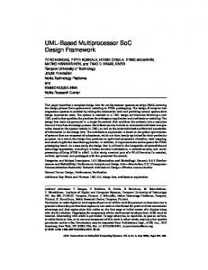
In this section we briefly introduce our previous work on scheduling of tasks and communications for MP SoC and illustrate the motivation of implementing system scheduler. Most of previous approaches to MP SoC scheduling try to schedule tasks and communications based on abstract hardware models, including types of processors and communication networks, bus topology, and allocation of processors [11]. Thus, the scheduling often neglects important factors such as task context switch overhead and communication delay due to the conflict in the buffers of communication network, degrading the accuracy maintained during the design process. In our work we use software model as well as hardware model, which consider more details of communication executions, including interrupt service routines and context switching for the software part and physical buffer sharing for the hardware part. This allows us to improve the accuracy of the scheduler design process. To solve the scheduling problem with our model, we use both ILP (integer linear programming) formulation and heuristic algorithm. For the ILP formulation, we first define communication delay model, which considers dynamic software behavior (interrupt, context switching, etc.). And then, we construct formulations for data dependencies and resource constraints. The heuristic algorithm is based on list scheduling, which is one of the most popular scheduling algorithms. Fig. 1 (c) shows a schedule for the task graph (a) implemented on the architecture (b). For the scheduler that implements the schedule, we can consider four candidates. The first is a dedicated hardware scheduler to be added to the system. Two are centralized schedulers: one implemented on µP1 and the other implemented on DSP. And the last one is a distributed scheduler that consists of two local schedulers, one for each processor. Fig. 2 shows two scheduler architectures (centralized architecture and distributed architecture) for the example in Fig. 1. In the figure L.S.1 and L.S.2 represent local schedulers implemented on the processors. And bold bidirectional arrowed lines represent synchronizations between a task and a scheduler or between two local schedulers. These two scheduler architectures implement the same
DSP Shared Memory
On Chip Bus On Chip Bus
Centralized scheduler (a)
(b)
Fig. 2. (a) Centralized scheduler. (b) Distributed scheduler.
schedule in Fig. 1 (c). But these architectures have their own characteristics. For example, the performance/area overhead of the centralized scheduler architecture depends on its location (µP1, DSP, or dedicated hardware), which is not true for the distributed scheduler architecture. The performance (area) overhead varies wide from 29.7% (0.3%) to 228.8% (0.7%) depending on the types of scheduler implementation. Therefore, we need to consider optimizing the scheduler implementation.
IV. System scheduler implementation After obtaining the schedule we implement the system scheduler. The main role of system scheduler is to realize the execution order of task and communication according to the schedule. To carry out this properly the system scheduler needs to synchronize itself with tasks and/or other schedulers. In this section first we introduce task execution and scheduler behavior model. And then, we address the design methodology to implement two scheduler architectures, centralized and distributed. And we also address the design space exploration for system scheduler implementation and trade-offs along the design decisions. A. Task execution and scheduler behavior model In our work we assume each task has its own input and output buffers so that it runs independently without any interference of other task’s execution. As shown in Fig. 3, we associate each task with start and done events. A system scheduler sends a start signal to (or receive a done signal from) a task. So, a task begins the execution as soon as it gets the start event from the scheduler and sends the done event to the scheduler after the execution. The start or done event can be an interrupt to a microprocessor or an input signal to a hardware block.
T3
µP1
T2
(a)
bus
T2 W1
W2
time
DSP µP1 T1
(b)
T2
Shared Memory
(c)
L.S.1
DSP T1 T2
Shared Memory
OS
T3 OS
OS
OS Comm. I/F
T3
µP1
R1 R2
T3
L.S. 2
DSP
T1
Comm. I/F
Comm. I/F
start and done
On Chip Bus
Architecture Constraints
Fig. 1. (a) Task graph. (b) MP SoC Architecture. (c) Schedulin g of task and communication.
T3 OS
sync
On Chip Bus
Fig. 3. Start, done and sync events of system scheduler.
Published in Proc. Asia South Pacific Design Automation Conference (ASP-DAC 2005), Shangai, China, January 18-21, 2005
In the case of a distributed scheduler, the local schedulers running on different processors need additional interprocessor synchronization mechanism. To this end we also associate sync event with local schedulers. The sync events can be implemented in the same way as start or done events. For the synchronization of tasks and schedulers we assume two kinds of synchronization. They are 1) intraprocessor synchronization between tasks and a local scheduler running on a same processor and 2) interprocessor synchronization between schedulers running on different processors. Intra-processor synchronization can be implemented with inter-process communication (IPC) of OS (e.g. POSIX message queue). Inter-processor synchronization requires additional interface (we call it scheduler interface) for the IPC, which will be explained through the rest of this section. The behavior of the system scheduler is modeled as a finite state machine (FSM) which is constructed based on the schedule table obtained from the static scheduling. The FSM has one start state and one done state for each task instance. State transition occurs whenever the scheduler sends a start signal to a task or receives a done signal from a task. In the case of distributed scheduler, a local scheduler may need additional states (sync states) for synchronization with other schedulers. B. Centralized and distributed scheduler architectures A system scheduler can be implemented as a centralized one or distributed over multiple processors with one local scheduler for each processor (a processor is not necessarily a programmable processor but can a hardware subsystem). Centralized scheduler can be implemented with a process running on a microprocessor or with a dedicated hardware block. Centralized scheduler consists of scheduler itself, interrupt service routine, and scheduler interface. Scheduler interface provides an interface to tasks running on other microprocessors by using interrupt and memory mapped registers. Fig. 4 illustrates an example of centralized scheduler architecture. Each local scheduler of a distributed scheduler can also be implemented with a single process on a microprocessor or with a dedicated hardware block. µP1 T1
T2 OS
Scheduler architecture selection
Schedule Table
Architecture Information
address data reg1
Interrupt reg2
User inputs
FSM Generation Automated flow
Generated FSM Scheduler and Scheduler interface implementation
Fig. 5. Implementation flow of system scheduler.
Fig. 5 shows the implementation flow. As a result of task and communication scheduling we obtain the schedule table. The schedule table contains instance names of tasks, task names, and start time and end time of task instances. During the step of scheduler architecture selection, we determine the scheduler architecture (centralized vs. distributed). With the schedule table and scheduler architecture information we construct an FSM. Fig. 6 shows a task graph, extended task graph, schedule table and FSM for the centralized scheduler. As shown in Fig. 6 (a) and (b), we extend the input task graph (TG) to an extended task graph (ETG) by adding to each edge two communication nodes representing write and read data transactions [2]. 1
1
T1
1
5
T1
1
1
TTW1
TTR31
5
T3 1
T3 1
1
T2
T2
(a) Instance name
Task name
Start time
End time
t1
T1
0
1
t3
T3
0
5
t1_t3W
T12T3_W
1
2
t2
T2
2
3
t2_t3W
T22T3_W
3
4
t1_t3R
T12T3_R
5
6
t2_t3R
T22T3_R
6
7
TTW2 1
TTR32
1
(b) initial
(d)
Fig. 6. (a) Task graph. (b) Extended task graph. (c) Schedule table. (d) FSM.
On Chip Bus
start done
Task and Communication scheduling
(c)
Comm. I/F
reg0
C. Implementation flow of system scheduler
Scheduler Interface
sync
Centralized scheduler Fig. 4. Architecture of centralized scheduler.
Fig. 7 shows the schedule table and FSM for µP1 processor in the example in Fig. 1 (b). As shown in Fig. 1, T1 and T2 are mapped on µP1. After finishing the execution of task instance t2_t3W, the next task instance t1_t3R starts execution on the other processor, thereby requiring interprocessor synchronization. In this case we add a sync state to the FSM.
Published in Proc. Asia South Pacific Design Automation Conference (ASP-DAC 2005), Shangai, China, January 18-21, 2005
Instance name
Task name
Start time
End time
t1
T1
0
1
initial
Source
t1_t3W
T12T3_W
1
2
t2
T2
2
3
t2_t3W
T22T3_W
3
4
DCT
Source VLC
Q
VLC
Interrupt Controller
Shared Memory
SW Archi. Comm. I/F
Comm. I/F
Q-1
AMBA AHB Motion Predictor
sync
Fig. 7. (a) Schedule table. (b) FSM.
Finally we can implement the scheduler and scheduler interface from the generated FSM. As shown in Fig. 5 the process of FSM generation and scheduler/interface implementation can be automated. D. Overhead analysis of system scheduler In this paper we consider performance overhead and area overhead as the overhead of system scheduler. Performance overhead is classified as intra-processor synchronization overhead and inter-processor synchronization overhead. Area overhead consists of area overhead of scheduler and/or scheduler interface and memory occupied by the interrupt service routine and local scheduler on microprocessor. Generally centralized scheduler has smaller area overhead and larger performance overhead than distributed scheduler. Centralized scheduler requires inter-processor communication on all start and done events. Distributed scheduler reduces such inter-processor synchronization overhead by using intra-processor communication between local schedulers and tasks. In Fig. 6, for example, there exist 7 computation and communication task instances and every task instance has a start event and a done event, so the scheduler has 15 states including the initial state. All state transitions use inter-processor synchronization. But in the case of Fig. 7, there is only one inter-processor synchronization between local schedulers the others are done by intraprocessor synchronization. The communication overhead of distributed scheduler might be smaller than that of centralized scheduler.
V. Experimental results
IDCT
Source
MB Encoder
MB Encoder
Comm. I/F Scheduler I/F
Motion Predictor
VLC Centralized scheduler
Motion Predictor
(b)
(c)
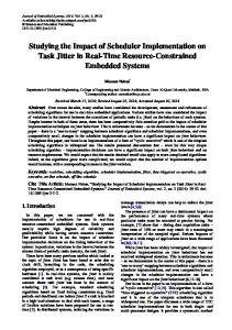
Fig. 8. (a) and (b) H.263 encoder system. (c) An implementation of centralized scheduler. Table 1 Performance and Area overhead of centralized and distributed schedulers Synchronization overhead SW task HW task Scheduler Scheduler scheduler Scheduler Centralized
685 ~ 895
1
N/A
Distributed
24 ~ 258
1
700
Area overhead Memory Area (# (byte) NAND) 400 192 (0.313 mm2) (0.076mm2) 800 100 (0.317 mm2) (0.338 mm2)
Table 1 shows performance and area overhead of the centralized scheduler and the distributed scheduler. The second, third, and forth columns show performance overheads of synchronization between software task and scheduler, between hardware task and scheduler, and between scheduler and scheduler, respectively. And the fifth and sixth columns represent memory size occupied by ISR and the scheduler and hardware area obtained by synthesis with Design compiler (Synopsys Inc.) with 0.35µ process library (Hynix Inc.). Table 2 Estimated and simulated time Estimated time (list scheduling) 30,620,262 cycles
A. Scheduler implementation with h.263 encoder We implement both centralized and distributed schedulers of h.263 encoder system. Centralized scheduler is implemented with dedicated hardware. Fig. 8 shows block diagram of H.263 encoder and the architecture of centralized scheduler. Here, Source and VLC are running on ARM9 processor and MB_Encoder and Motion Predictor are implemented as dedicated hardware blocks. For the distributed scheduler, local schedulers are implemented with a process running on the ARM9 microprocessor and two hardware blocks (one in MB Encoder and the other in Motion Predictor). For the local scheduler on ARM9, we use eCos message box [15] to implement intra-processor synchronization.
Comm. I/F
(a)
(b)
(a)
ARM9
Macro block encoder
Simulated time (Centralized scheduler) 30626,652 cycles
Simulated time (Distributed scheduler) 30,621,752 cycles
Table 3 Estimation and simulation time Estimation time (list scheduling) 0.345 sec.
Simulation time (Centralized scheduler) 140 min. (8400 sec.)
Simulation time (Distributed scheduler) 140 min. (8400 sec.)
Table 2 and Table 3 show the simulated cycles and simulation time compared with estimated cycles and estimation time obtained by list scheduling. The simulation is done with centralized and distributed schedulers, each for encoding 10 frames of QCIF sized images (1 for intra frame encoding and 9 for inter frame encoding). We show the input images and encoded images in Fig. 9 to demonstrate that the proposed approach really works.
Published in Proc. Asia South Pacific Design Automation Conference (ASP-DAC 2005), Shangai, China, January 18-21, 2005
ARM9 #1
ARM9 #2
ARM9 #n-1
ARM9 #n
T1
T2
T3
T4
T2n-3
T2n-2
T2n-1
T2n
T4n
T4n-1
T4n-2
T4n-3
T2n+4
T2n+3
T2n+2
T2n+1
(a) ARM9 #1
ARM9 #n
T1
T2
T3
T4
T4n-3
T4n-2
T4n-1
T4n
T8n
T8n-1
T8n-2
T8n-3
T4n+4
T4n+3
T4n+2
T4n+1
Fig. 9. Input images and encoded images by h.263 encoder.
(b)
Fig. 11. (a) CASE1: 4 tasks mapped on each ARM9. (b) CASE2: 8 tasks mapped on each ARM9. Perform ance overhead (C ASE 1)
250
Perform ance overhead (C ASE 2) 250
No delay + C entr. O ver. C entr. O ver.
200
% overhead
With the h.263 encoder example we don’t clearly see the effect of the system scheduler overhead (less than 1%), because task execution times are much larger than the scheduler overhead. So, we build synthetic examples and perform experiments with them to see the effect of system scheduler overhead.
150
% overhead
B. Design space exploration with synthetic examples
No delay + Dist. O ver. Dist. O ver.
100 50
150
50 0
0
ARM9 T1
T2
SubSystem n (a)
Comm. I/F
6
8
0
10
2
4
6
# subsystem s
8
10
Fig. 12 shows the percentage performance overhead under the assumption that every task has 1,700 cycles of execution time. The curves are obtained for centralized and distributed schedulers. There are two curves for each type for each case. One is obtained by scheduling with the scheduler overhead and the other is obtained by scheduling without the overhead but adding the scheduler overhead in Table 1 to the results of the scheduling. As the number of subsystems increases the errors due to ignoring the scheduler overhead also increase. So, as the size of a system increases, we need to consider the scheduler architecture and overhead at the time of scheduling.
Comm. I/F
Local Bus Bridge
(b)
Fig. 10. (a) Target architecture. (b) Detailed architecture of a subsystem.
Performance overhead per task ( CASE 1) 900 800 700 600 500 400 300 200 100 0
Performance overhead per task ( CASE 2)
Centr. Over. Sched. w/ Centr. Over. Dist. Over.
# cycles
Fig. 10 shows the target architecture used in this experiment. The architecture consists of a number of homogeneous subsystems. As the communication network we use hierarchical bus architecture including local bus architecture and system bus architecture, as shown in the figure. We assume that we use only one clock, such that the subsystems and the system bus use the same clock. A subsystem consists of one ARM9, shared memory, local onchip bus, and bus-bridge between a local bus and the system bus as shown in Fig. 10 (b). And we also assume that the communication delay of the bridge and the system bus delay are both 2 [12]. The application is a ping-pong token ring example, where every task gets the two token data from previous tasks and checks the data value and passes it to the next tasks. Fig. 11 shows the task graphs of the example and mapping on the target architecture. In the mapping of the tasks to the processor we have two cases. We assume that 4 tasks run on each ARM9 in CASE 1 and 8 tasks run on each ARM9 in CASE 2.
4
# subsystem s
Fig. 12. Performance overhead for (a) CASE 1 and (b) CASE 2.
Shared Memory
OS System Bus
2
Sched. w/ Dist. Over. 0
2
4
6
# subsystems
8
10
# cycles
SubSystem 2
No delay + Dist. O ver. Dist. O ver.
100
0
Subsystem1
No delay + C entr. O ver. C entr. O ver.
200
900 800 700 600 500 400 300 200 100 0
Centr. Over. Sched w/ Centr. Over. Dist. Over. Sched w/ Dist. Over. 0
2
4
6
8
10
#subsystems
Fig. 13. Performance overhead per task for (a) CASE 1 and (b) CASE 2.
As shown in the Fig 13, the scheduler overhead per task decreases as the number of subsystems increases. This is because as more subsystems run in parallel, the average overhead decreases. This also explains why the errors in Fig. 12 increase as the number of the subsystems increases.
Published in Proc. Asia South Pacific Design Automation Conference (ASP-DAC 2005), Shangai, China, January 18-21, 2005
Reference
are a ov e rhe ads 3,5 3
[1]
area (mm2)
2,5 2
[2]
1,5 1 0,5 0 2
3
4
5
6
7
8
9
#sub systems
centralized
distributed
Fig. 14. Area overhead of centralized and distributed scheduler architecture.
Fig. 14 shows how the area overhead varies according to the number of subsystems. In the figure the area overhead also includes the memory size occupied by the ISR and local scheduler on the processor. The area overhead is less than 3mm2 for less than 9 subsystems. This overhead spans roughly from 0.3% (in the case of centralized scheduler) to 0.7% (in the case of distributed scheduler) when compared to the total chip size [13]. Here, the area overhead of the hardware part (scheduler and/or scheduler interface) is obtained by synthesis with Design compiler (Synopsys Inc.) with 0.35µ process library (Hynix Inc.) and the memory size is converted to the area according to [14].
[3]
[4]
[5]
[6] [7]
[8]
VI. Conclusion We address in this paper the design methodology to implement a system scheduler, which realizes schedules for task executions and communication transactions on an MP SoC. For the architecture of the scheduler we propose two schedulers, centralized scheduler and distributed scheduler. And we present how to exploit the trade-offs through design decisions on the type of scheduler architecture. We implement both of centralized and distributed schedulers with the example of h.263. The scheduler performance overhead is less than 1% compared to that of the total system. And the area overhead is 0.39mm2 (centralized scheduler) and 0.66mm2 (distributed scheduler) including hardware area and memory for ISR and scheduler, which is small enough to be negligible. To see the effect of the scheduler overhead we perform experiments with synthetic examples. The results show that the performance and area overhead varies from 29.7% (0.3%) to 228.8% (0.7%) depending on the types of scheduler implementation.
[9]
[10]
[11]
[12] [13] [14] [15]
A. A. Jerraya, S. Yoo, N. Wehn, and D. Verkest, Embedded Software for SoC, Kluwer Academic Publishers, 2003. Y. Cho, G. Lee, S. Yoo, K. Choi, and N. Zergainoh, “Scheduling and timing analysis of HW/SW on-chip communication in MP SoC design,”, Proc. Design Automation and Test in Europe, pp. 132 ~137 suppl., 2003. J. M. Paul, A. Bobrek, J. E. Nelson, J. J. Pieper, and D. E. Thomas, “Schedulers as model-based design elements in programmable heterogeneous multiprocessors,” Proc. Design Automation Conference, pp. 408 ~ 411, 2003. J. Brest and V. Zumer, “A performance evaluation of list scheduling heuristics for task graphs without communication costs,” Proc. International Workshop on Parallel Processing, pp. 421 ~ 428, 2000. P. Eles, A. Doboli, P. Pop, and Z. Peng, “Scheduling with bus access optimization for distributed embedded systems,” IEEE Transactions on Very Large Scale Integration (VLSI) Systems, vol. 8, no. 5, pp. 472 ~ 491, 2000. M. Engels and T. Meng, “Rapid prototyping of a real-time video encoder,” Proc. International Workshop on Rapid System Prototyping, pp. 8 ~ 15, 1994. J.L. Pino and E.A. Lee, “Hierarchical static scheduling of dataflow graph onto multiprocessors,” Proc. International Conference on Acoustics, Speech, and Signal Processing, pp. 2643 ~ 2646, 1995. F. Karim, A. Mellan, A. Nguyen, U. Aydonat, and T. Abdelrahman, “A multilevel computing architecture for embedded multimedia applications,” IEEE Micro, Vol. 24, pp. 55 ~ 66, 2004. B. Falsafi and D. A. Wood, “Scheduling communication on an SMP node parallel machine,” Proc. Internal Symposium on High-Performance Computer Architecture, pp. 128 ~ 138, 1997. J.-Y. Colin and M. Nakechbandi, “Scheduling tasks with communication delays on a two-level virtual distributed system,” in Proc. Euromicro Workshop on Parallel and Distributed Processing, pp. 344 ~ 348, 1999. K. Lahiri, A. Raghunathan, and S. Dey, “System-level performance analysis for designing on-chip communication architecture,” IEEE Transaction on Computer-Aided Design of Integrated Circuits and Systems, vol. 20, no. 6, pp. 768 ~ 783, 2001. ARM Inc., AMBATM Specification (Rev 2.0), available in http://www.arm.com/. FAMILY, available in ARM, Inc., ARM9TM http://www.arm.com/. NEC Inc., “IC memory selection guide,” available in http://www.nec.com. Redhat Inc., eCos, available in http://www.redhat.com/embedded/technologies/ecos/.
Published in Proc. Asia South Pacific Design Automation Conference (ASP-DAC 2005), Shangai, China, January 18-21, 2005