NoC Topologies Exploration based on Mapping and Simulation Models Luciano Bononi, Nicola Concer, Miltos Grammatikakis Computer Science Department University of Bologna {bononi, concer}@cs.unibo.it, Computer Science Group, General Sciences TEI-Crete, Heraklion, Crete, Grece,
[email protected]
Abstract NoC architectures are considered the next generation interconnect systems for multiprocessor systems-onchip. Selection of the network architecture and mapping of IP nodes onto the NoC topology are two important research topics. In this paper we compare well known NoC interconnect systems, specifically, Ring, 2d-Mesh, Spidergon and unbuffered Crossbar using theoretical uniform traffic based on the request/reply paradigm as well as a realistic traffic based on a Mpeg4 application. The IP mapping is automatically computed by the SCOTCH partitioning tool based on defined embedding quality criteria that respect multiple topological constraints. Our simulation results indicate that, in general, Ring and Spidergon provide good tradeoffs between cost, performance, scalability, while Mesh is unable to exploit extra communication paths when using simplified deadlock-free routing scheme under irregular traffic. We also highlight the unexpectedly poor performance obtained in some scenarios by directly connected unbuffered Crossbar architectures. 1. Introduction Network-on-chip (NoC) provides a robust, high performance, scalable and power-efficient communication infrastructure for configuring multiprocessor system-on-chip (MPSoC) components [1, 2]. A NoC usually consists of a packet-switched onchip micro-network [4], foreseen as the natural evolution of traditional bus-based solutions, such as AMBA [5], and IBM Core Connect [6]. Innovative NoC architectures include the LIP6 SPIN [7], the MIT Raw [8], the VTT (and various Universities) Eclipse [9], Nostrum [10], the Phillips Æthereal NoC [11], Stanford/Uni-Bologna’s Netchip [12] and STMicroelectronics’s STNoC architecture [13, 14]. All these architectures are based on direct point-to-point topologies, in particular Meshes, tori and fat trees [3,4]. They are configured with small, high-performance routers that implement and network interface devices
and offer simple and efficient routing algorithms. Future NoC systems target asynchronous communication, regular and efficient VLSI layout with predictable wire lengths and path delays, reduced network congestion based on QoS mechanisms, improved reliability and fault tolerance. A major challenge for predicting performance and scalability of a particular NoC architecture relies on accurate specification of expected application traffic. For example, it has been estimated that SoC performance may vary up to 250% depending on NoC design, and up to 600% depending on communication traffic [15]. Previous researchers have studied application embedding onto conventional NoC topologies. Hu and Marculescu examined mapping of a heterogeneous 16core task graph representing a multimedia application, onto a Mesh NoC topology [23]. Murali and De Micheli used a customized tool (called Sunmap) to map a 12core heterogeneous task graph representing a video object plane decoder and a 6-core DSP filter application onto a 2d-Mesh or 2d-torus NoC topology using different routing algorithms [24, 25]. The proprietary Sunmap tool, proposed at Stanford and Bologna Universities, performs RTL-level NoC topology exploration by minimizing area and power consumption requirements and maximizing performance for various routing algorithms. The Xpipes compiler [12] can extract efficient synthesizable SystemC code for all network components, i.e. routers, links and interfaces, at the cycle- and bit-accurate level. Our study considers efficient and automated static mapping of complex application task graphs onto some relevant NoC architectures computed through the SCOTCH partitioning tool [21]. In addition, OMNeT++ simulation [17] and analysis is performed for examining dynamic performance of traditional Ring, 2d-Mesh, Spidergon and unbuffered Crossbar architectures. The paper is organized as follows: in section 2 we sketch the NOC architectures considered in the analysis; in section 3 we outline the application mapping problem, tools, metrics and near-to-optimal solutions adopted for mapping the Mpeg4 application task-graph; in section 4 we illustrate
(a)
(b)
(c)
(d)
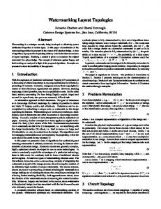
Figure 1.The four topologies analyzed in this paper: (a) 2D Mesh, (b) Ring, (c) Spidergon and (d) Crossbar analysis results and comments; in section 5 we draw some conclusions and future work directions. 2. NoC architectures IPs are connected to a NoC switch by a network interface (NI) incorporating connection management and data fragmentation functions. NoCs must use a regular, scalable and simple network topology, characterized by the space locality of modules connected by short links. Moreover, they must provide small, fast and simple routers in order to maximize network performance and minimize the interconnect 's power consumption and area. For these reasons most of the networks proposed in literature, including those analyzed in this paper, are packet-based. Each packet is split into data units called flits and channel buffer queues are defined as multiples of flit data-unit. Packet forwarding is usually deterministic shortest-path and based on a local signal-based flow control. The adopted switching strategy is wormhole routing. In wormhole, the head flit of a packet is actively routed towards the destination by following forwarding information on routers, while subsequent flits are passively switched by pre-configured switching functions to the output queue of the channel belonging to the path opened by the head flit. A packet is forwarded when buffer space is available on the input queue of the channel of the next switch in the path. In NoC domain, flit-based wormhole is generally preferred to virtual cut-through or packetbased circuit switching because its pipelined nature facilitates flow control and end-to-end performances, with low packet-overheads and low buffer requirements. However, due to the distributed, finite resources and possible circular waiting conditions, complex deadlock conditions may arise, involving routing-based solutions. The considered 2D Mesh architecture (Figure 1a), resolves this point through the dimension order algorithm. This deadlock avoidance routing algorithm limits the path selection [2] by forwarding flits towards their destination first along the horizontal link until the column of the target node is reached. Then, flits are forwarded along the vertical link up to the target node. The Ring architecture (Figure 1b) deals with routing
deadlock using virtual channels (VC) [2,3]; VCs are implemented by multiple output queues for each physical link. In literature a number of VC selection algorithms can be found [2]. The one we adopted is called multiple dateline VC selection algorithm [26]: next VC to assign to a packet depends on the current node ID, the packet destination ID and the network diameter D. The algorithm first computes the values SOURCE = (current_ID mod D) and DEST = (destination_ID mod D), then the VC is chosen as follows: if(SOURCE >DEST) use VC0 else use VC1. This algorithm resolves the routing deadlock and, under random traffic, also improves the performance of the Ring architecture by optimally exploiting its resources [26]. The Ring, routing strategy is straightforward: clockwise or counter-clockwise direction are selected depending on the shortest path. The Spidergon architecture, reported in Figure 1c, is similar to a bidirectional Ring enriched by across links between opposite nodes [13, 14, 16] (but the real physical layout of this architecture slightly differs from the Figure 1c and can be found in [29]). For each node a clockwise, counter-clockwise and across link is present. Some of the most interesting characteristics of Spidergon are: i) regular network topology, ii) vertex symmetry (same topology appears from any node), iii) constant degree (equal to 3) translating in router simplicity and efficiency and iv) constant network size extendibility (equal to 2). In this study, Spidergon NoC adopts a proprietary routing algorithm. By assuming N as the number of nodes (network size) and D as the Spidergon diameter, if the target node for a packet is at distance D > N/4 on the external Ring (that is, in the opposite half), then the across link is traversed first, to reach the opposite node and then, depending on the target’s position, a clockwise or counter-clockwise direction is maintained. Spidergon avoids deadlock by adopting some restriction rules on the use of channels in a way similar to the dimension order used by the Mesh routing algorithm. In this way virtual channels can be avoided reducing the architecture’s buffer need. In this
PE
PE
PE
PE
SE
SE (a)
(b) PE
PE
PE
PE
PE
PE
PE
PE
network for requests, and one for replies. At each clock cycle routers select the flit to forward (if any) on each output channel by selecting the virtual network with round robin policy. Moreover, once the VN has been selected, routers in the Ring architecture select the source VC (from which to forward a flit) by adopting the “winner takes all” [3] algorithm. The Crossbar architecture does not require virtual networks, since request and reply packets pass through different physical channels, thus protocol deadlock can not happen. Mapping Task Graphs onto NoC Architectures
SE
PE
SE
PE
SE
PE
SE
PE
PE
SE
SE
PE
SE
PE
PE
SE
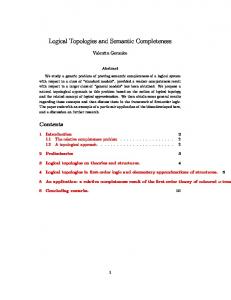
(c) Figure 2. Task Graphs for 2-node rooted forest (a), 4node rooted tree (b) and 2-node rooted 2 disjoint forest (c). paper we analyze also the Crossbar interconnect: an unbuffered direct network, shown in Figure 1d. A full Crossbar is prohibitively expensive (in terms of number of links), but it gives an optimal solution in terms of embedding quality metrics for all patterns. Modern Crossbars interconnect IP blocks with a variety of data widths, clock rates and socket or bus standards have been proposed, e.g. AHB, OCP or AXI. Although system throughput, latency and scalability problems can be dealt with by implementing the Crossbar as a multistage network based on small Crossbars, a relatively simple, low-cost alternative for NoC realization is the unbuffered Crossbar switch. In our model, a source node requiring a channel to send packets to a specific destination signals the request to the Crossbar arbiter, which eventually grants the access to the shared directed link. In case of multiple requests for the same channel, the arbiter selects the contention winner with a round robin policy. The tests we will discuss in the following are based on a request/response application paradigm which may induce to a messagedependent deadlock [25] (also called protocol deadlock [3,4]). This problem is given by the dependency between the request and reply packets on the target’s input and output channels. The adopted solution is based on the use of separated virtual networks (VN) for each kind of packet [4,25]. Specifically in the Ring, Mesh and Spidergon architectures we adopted one virtual
Mapping of an application on a specific architecture is a typical parallel computing problem. Figure 3 illustrates an Mpeg4 task graph, as described in [18]. Task graphs are composed by basic IP blocks with clear, unambiguous and self-contained functionalities, interacting together to form a NoC application. The NoC topology model is an abstraction of the actual NoC architecture onto which the application is deployed and run. Due to the fixed nature of the SoC systems the main task of a mapping algorithm consists in selecting an appropriate deployment of IP blocks that balances the NoC communication load (expressed in Mb/s in the task graph).
Figure 3. The mpeg4 video decoder task graph. Optimal mapping of general applications onto arbitrary NoC topology graphs is known to be NP-hard [19]. Thus, embedding heuristics usually try to find a nearoptimal mapping solution by appropriately defining a cost function and trying to minimize it [20]. In our work, we used the SCOTCH partitioning tool together with various free packages, such as AT&T’s Neato for graph visualization, McKay’s Nauty for symmetry and topological metrics and Karypis and Kumar’s Metis for fast, multilevel graph partitioning [20]. To compute mapping of source (application) graph onto target (topology) graphs representing prospective NoC topologies. SCOTCH provides efficient libraries based on recursive bi-partitioning for statically mapping any possibly-weighted source graph (GS) onto any possibly-
•
•
Edge dilation of an edge of Gs is defined as the length of the path in GT onto which an edge of GS is mapped. The dilation of the embedding is defined as the maximum edge dilation of Gs. This metric measures latency overhead during point-to-point communication in the target graph GT. Edge expansion refers to a weighted-edge graph GS. It multiplies dilation of each edge of GT with its corresponding edge weight. The edge expansion of the mapping is defined as the maximum edge expansion of Gs. This metric also represents latency overhead for weighted graphs.
These two functions have several interesting properties: they are simple to compute, allowing incremental updates performed by iterative algorithms and their minimization favors the mapping of intensively intercommunicating processes onto nearby processors regardless the type of routing implemented on the target NOC [21]. 3. Performance evaluation Spidergon, Ring, Mesh and Crossbar architectures and their near-to-optimal mapping solutions have been modeled using a flit-accurate simulator based on the OMNeT++ framework [17]. Each architecture has been configured with synchronous interconnected routers, each one linked to a single external IP through a network interface device [16]. Depending on the simulated scenario, each IP acts either as a processing element (PE), or as a storage element (SE). PEs (called
Architectures' Buffer amount 0 64 1152
0 32
624 576
0 24 Network Size
weighted target graph (GT) [21]. This algorithm has been initially proposed to map processes of a task graph onto processors in multiprocessor systems. SCOTCH adopts a divide and conquer approach to the problem. It recursively allocates subsets of processes to subsets of processors of the machine. It starts by considering a set of processors, also called domains, containing all the processors of the target machine and with which is associated the set of all the processes to map. At each step the algorithm bipartitions a yet unprocessed domain into two disjoint sub-domains, and calls the graph bipartitioning algorithm to split the subset of processes associated with the domain across the two sub-domains. Whenever a domain is restricted to as single processor its associated processes are assigned to it and recursion stops. We modified this algorithm to reach our requirements i) Processes are the nodes in the application task graph ii) Processors are the Network Interfaces connected through the NoC iii) To each NoC node corresponds one and only one process. The metrics adopted by the SCOTCH to compute a semi-optimal mapping are the Edge Dilation for unweighted task graph and Edge Expansion for the weighted ones:
456 432
0 20
372 360
0
0
0 8 0
1536
768
576
Crossbar Ring
480
Mesh Spidergon
384 288 288
16
12
1344
288 204 216 192 120 144
500
1000 Buffer amount (flits)
1500
2000
Figure 4. Total buffer space for NoC architectures of different size also initiators) generate packet requests directed to the SEs nodes (Targets) according to the considered application task graph. Initiators are provided with infinite FIFO output queues that temporarily store the produced packets once the underlying NoC is not able to absorb them at a sufficient speed. Target nodes are provided by infinite input and output queues: they receive requests coming from PEs and produce response packets whose length is defined by the application task graph. The choice to assign infinite queues all the PEs and SEs in all simulations we performed allows us to focus the network performance by including effects of deadlock avoidance solutions, and to avoid external devices’ characteristics to play any biasing role in the pure network performance analysis. Routers are provided with a single input register and a finite output queue for each virtual channel. Routers forward incoming flits according to the path computation algorithm provided that the following router has enough buffer room to store them. Otherwise, flits are temporarily stored in the (finite) selected channel’s output queue. On the other hand, in Crossbars (who has no intermediate buffers) flits remain in the infinite output buffer of the initiator until they can be injected into the network. In our simulator, the packet size is measured in flits so that results are valid independently from actual flit’s bit-size. Since we focus on topological constraints rather than real system dimensioning, we assume that each channel is able to transmit one flit per clock cycle. All considered architectures have been modeled using similar routing and PE/SE components, adapted to the specific architecture constraints and deadlock avoidance solutions. In our modeling approach, we assume each
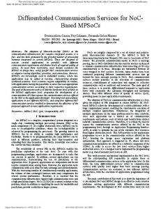
output buffer of intermediate routers with a constant size of three flits (this is an implementation choice, and tests indicate that for the considered scenarios the size of buffers does not change qualitative results. Figure 4 summarizes the minimal total buffer memory (in flits) required by each architecture with homogeneous routing and deadlock properties, as a function of the number of nodes, the number of physical output channels, the number of virtual channels and the number of virtual networks. Data in Figure 4 is important because as shown in [25, 27] buffer area significantly dominates the total routers area size. In Mesh and Spidergon the required buffer amount is comparable (and lower than Ring), and the Spidergon buffer allocation becomes lower than Mesh when the network size increases (>16). Thanks to the dimension order routing algorithms adopted in Mesh and Spidergon, these architectures avoid deadlock with no virtual channels. The Ring architecture instead requires two virtual channels for each physical link doubling the architecture’s buffer needs. The Crossbar is a direct network with no internal buffer and no VCs, hence its values in the graph of Figure 4 are equal to zero. 4.1 Uniform traffic Simulation results We compared the four considered architectures under different theoretical application scenarios by computing a per-application semi-optimal mapping through the SCOTCH tool, and analyzing the given configuration through our OMNeT++ simulation tool. In particular, we modeled the uniform forest, tree and disjoint forest scenarios whose reference task graphs are sketched in Figure 2. These theoretic task graphs allow us to abstract a number of possible application traffic patterns for SoCs that are usually provided with a central memory connected to the system by several access points and shared by a great number of processing elements. In a T-node rooted forest scenario (Figure 2a) a task graph of N nodes is composed by T SEs and N-T PEs. The T targets are uniformly selected by all the initiators of the network. In our experiments we modeled a 4 node routed forest (T=4, note that Figure 2a shows only 2 targets for sake of clarity). In a T-node rooted tree scenario (Figure 2b) the task graph in composed by T targets and N-T initiators. Initiators are split in T disjoint groups, each one associated to one target. Each PE in one group communicates only to the SEs associated to its group. In our experiments we modeled a 4-node rooted tree scenario. The T-node rooted F-disjoint forest task graph (Figure 2c) is a combination of the two previous scenarios. It considers a network composed by T*F targets and N(T*F) initiators. Initiators and targets are grouped in F
disjoint groups. Each initiator in a group uniformly sends its requests to the T targets belonging to its own group (see Figure 2c). In our experiments we used a 2node rooted 2 disjoint forests (T=2 and F=2).We modeled requests and replies to have the same average length, and to one request corresponds exactly one reply. Figures 5a, 5b and 5c show the average throughput for the delivery of replies in each considered architecture, measured on each initiator as follows:
Th rep = (Total Received Reply Packets) * (Avg. Reply Size) (Elapsed Time) * (Number of Initiators)
By assuming uniform traffic distribution and asymptotic offered load (see below), the reply delivery throughput follows the initiators’ injection rate until the NoC saturates, or all the targets reach the maximum absorption capacity (which is one flit/cycle/target). After the saturation point, routers become insensitive to the real offered load rate, while initiators’ infinite output queues quickly grow to infinite. To compute the curves in Figure 5 we simulated an asymptotic offered load equal to the initiators’ maximum injection rate (1 flit/cycle/initiator). Note that initiators are always more than targets. Results in Figures 5a, 5b and 5c are calibrated based on the theoretical upper bound delivery throughput computed by assuming asymptotic offered load, an ideal network (a network with no bottlenecks) and targets with infinite buffer capacity for receiving requests. Under these assumptions, this index can be computed as: (Number of Targets) / (Number of Initiators). By examining the throughput of replies on the 4-node rooted forest, reported in Figure 5a, we see that for small network sizes (from 12 to 24 nodes) performance of all considered topologies is quite distant from the theoretical upper bound. As the network size grows the difference decreases. This effect is mainly due to the Target/Initiator ratio (targets are 4, initiators are N-4): in small networks (N