the user's utterances from other voices without using a speaker identification ..... was segmented manually to include silence durations. On the other hand, the ...
Noise robust speech recognition for voice driven wheelchair Akira Sasou, Hiroaki Kojima National Institute of Advanced Industrial Science and Technology (AIST) {a-sasou,h.kojima}@aist.go.jp
Abstract In this paper, we introduce a noise robust speech recognition system for a voice-driven wheelchair. Our system has adopted a microphone array system in order for the user not to need to wear a microphone. By mounting the microphone array system on the wheelchair, our system can easily distinguish the user’s utterances from other voices without using a speaker identification technique. We have also adopted a feature compensation technique. By combining the microphone array system and the feature compensation technique, our system can be applied to various noise environments. This is because the microphone array system can provide reliable information about voice activity detection to the feature compensation method, and the feature compensation method can compensate for the weak point of the microphone array system, which is that the microphone array system tends to be less effective for omni-directional noises. Index Terms: noise robust speech recognition, wheelchair
W130xD10xH5mm. The circuit boards were placed in the diagonal directions of the black square sponges. Because these black sponges are placed on the edges of the arm rests, the user's head never touches the microphone array system even when there are involuntary movements.
1. Introduction Various voice-driven wheelchairs have already been developed which try to make it possible for disabled people to move according to their own will [1]. However, conventional voice-driven wheelchairs still have some problems. For instance, conventional voice-driven wheelchairs have adopted a headset microphone which can record the user's command voice in higher SNR even with the presence of surrounding noises. However, disabled people need to put this headset microphone on each time they use the voice-driven wheelchair. When the headset microphone moves away from the position of the mouth, they also need to be able to adjust the position of the headset microphone by themselves. Because these actions are not always easy for disabled people, we think headset microphones are not practical. Our goal is to develop a voice-driven wheelchair that does not need disabled people to wear any microphones on themselves.
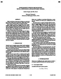
2. Microphone array system When considering surrounding-noise problems, we'd like to put microphones close to the user's mouth. However, such microphones would be dangerous for some disabled people, for instance, those with cerebral palsy with involuntary movements. So the microphone should be placed far enough from the user's mouth so as not to touch the user’s head. In this case, however, speech recognition systems suffer from interference from surrounding noise and other voices. In order to overcome such noise problems, we have adopted a microphone array system instead of a headset microphone. Figure 1 shows the wheelchair we have developed. Our microphone array system consists of two circuit boards. Each circuit board has four silicon microphones soldered every 3cm linearly. The size of each circuit board is
Figure 1: The developed wheelchair with microphone array system.
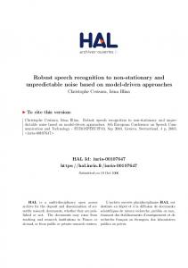
2.1. Detection of user utterance and noises The speech recognition system should accept only the user's voice and should reject voices coming from outside. If we adopt a speaker identification technique for this purpose, we need to train the system every time a new user uses the wheelchair. This would not be practical. Instead, because our wheelchair has adopted a microphone array system, we can estimate the position or the arrival direction of sound sources. That is, the mouth position of a seated user is always in a certain area, which is around the center of the seat at the sitting height. We call this as the user-utterance-area (UUA). When an observed voice's position is estimated to be in the user-utterance-area, the speech recognition system accepts the voice. On the other hand, when an observed voice is judged to come from the outside, the speech recognition system rejects it. So, by adopting the microphone array system, we can easily distinguish the user's voice from others’ voices without any training procedures. We have adopted the MUSIC [2] method for estimating the position and arrival direction of noises. We assume that a sound source occurring in the user utterance area is received as a spherical wave by the microphone array system. The steering vectors in the user utterance area are defined as follows.
Pq = [ Pxq , Pyq , Pzq ]T , q = 1,L,8
(Px
Rq = p q − p 0 =
τ q = Rq / v ,
[
− Px0 ) + (Pyq − Py0 ) + (Pz q − Pz0 ) 2
q
2
Y
2
c
g q = g (ω, Rq )
a(ω, P0 ) = g1e − jωτ1 ,L, g 8 e − jωτ 8
]
T
(1)
5
where P0 represents the position of the sound source in the user utterance area, P1 L P8 represent the positions of microphones, Rq is the distance between the qth microphone and the sound source, and v is sound velocity. g (ω , Rq ) is a
1
6
2
7 8
3
R5
distance-gain function. We actually measured the distancegain function at several distances, and made a model function fitted to the measured values. On the other hand, we assume that sound sources outside the wheelchair are received as plane waves the by microphone array system. The steering vectors are thus defined as
P0
c k = [cos φk cos θ k , cos φk sin θ k , sin φk ]
User Utterance Area
rq ,k = Pq ⋅ c k , Tq ,k = rq ,k / v
b(ω, θ k , φk ) = [e
jωT1, k
,L, e
X 4
jωT8 , k T
(2)
]
where ck is the normal line vector of plane wave emitted by the kth outside sound source. The spatial correlation matrix is defined as N (3) R (ω ) = (1 / N ) y (ω , n) y H (ω , n )
Figure 2: Schematic diagram of wave propagation.
2.2. Enhancement of user utterance
(4) R(ω ) = E(ω )L(ω )E −1 (ω ) where E(ω ) denotes the eigenvector matrix, which consists of the eigenvectors of R (ω ) as E(ω ) = [e1 (ω ),L, e 8 (ω )] ,
When the user utterance and noises occur simultaneously, we need to suppress the noises in order to recognize the user utterance correctly. For this purpose, we have adopted the modified minimum variance beamforming (MVBF) technique [3]. The modified MVBF has the ability to design a spatial inverse filter of high performance with a relatively small number of data. This ability is suitable for our wheelchair application, because, in order for the microphone array system to suppress noise sources moving around the wheelchair, the sound source localization and the spatial inverse filter need to be updated in a short time.
L(ω ) = diag(λ1 (ω ),..., λ8 (ω ) ), λ1 (ω ) ≥ L ≥ λ8 (ω ) (5).
In the following, we assume the estimated position of user utterance is P0 , the estimated number of noises is K, and the
∑ n =1
where y (ω, n) = [Y1 (ω, n),L, Y8 (ω , n)]T , and Yq (ω, n) represents the FFT of the nth frame received by the qth microphone. The eigenvalue decomposition of R(ω ) is given by
and L(ω ) denotes the eigenvalue matrix, which is defined as The number of sound sources is estimated from the eigenvalues as follows. First we evaluate the threshold value which is defined as C (1−C ) (6) Tegn (ω ) = λ1 egn (ω ) × λ8 egn (ω ),0 < Cegn < 1
where Cegn is a constant which is adjusted experimentally. The number of sound sources N snd (ω ) is then estimated as the number of eigenvalues larger than the threshold value.
λ1 (ω ), L , λ N (ω ) ≥ Tegn (ω )
(7)
snd
The eigenvectors corresponding to these eigenvalues form the basis of signal subspace E s (ω ) = [e1 (ω ),L, e N (ω )] . The snd
remaining eigenvectors E n (ω ) = [e N +1 (ω ),L, e 8 (ω )] are the snd basis of the noise subspace. User utterances are detected according to the following method. First we search for the position P0 that absolutely maximizes the following value in the user utterance area. 2 Q(P) = 1 / a H (ω , P)E (ω ) , P = arg max Q(P) (8)
∑ ω
n
0
k =1
The third term σI is the correlation matrix of the virtual background noise, and the power of the virtual noise σ can be arbitrarily chosen. By using this virtual correlation matrix, the coefficient vector of the spatial inverse filter becomes
w (ω ) =
V −1 (ω )a(ω , P0 ) a H (ω , P0 )V −1 (ω )a(ω , P0 )
(11)
The FFT of the emphasized speech signal is given by
x(ω , n) = w H (ω ) ⋅ y (ω , n) .
(12)
P∈UUA
If the absolute maximum value Q(P0 ) exceeds the threshold value Tusr , we judge that the user made a sound. The arrival directions of sound sources outside are evaluated as directions that locally maximize the following value
U (θ ,φ ) = 1 / ∑ b H (ω,θ ,φ )E n (ω ) . 2
ω
estimated arrival directions of noises are given by (θ k , φk ), k = 1,L, K . Instead of using the estimate of spatial correlation matrix R (ω ) , the modified MVBF uses the following virtual correlation matrix. V (ω ) = a(ω , P0 ) ⋅ a H (ω , P0 ) + (10) K H ∑ b(ω ,θ k , φ k ) ⋅ b (ω ,θ k ,φ k ) + σI
(9)
3. HMM based feature compensation The microphone array system is very effective at suppressing directional noise sources. However, it tends to be less effective for omni-directional ones. In order to make the speech recognition more robust to various noise environments, we also adopt the HMM based feature compensation method [4] in addition to the microphone array system.
There is another advantage of combining the microphone array system and the feature compensation method. The feature compensation method needs precise voice activity detection, as described below. Generally, however, it is not always easy to detect voice active duration from a noisecorrupted speech signal of a single channel. Such poor accuracy of voice activity detection causes degradation of feature compensation accuracy. On the other hand, the microphone array system can detect voice activity even with the presence of surrounding noises. In our system, therefore, the feature compensation method can utilize the reliable voice activity detection from the microphone array system, which guarantees the feature compensation accuracy. The feature compensation method assumes that a distortion of the noisy speech feature in the cepstral domain can be divided into a stationary and a non-stationary distortion component. The temporal trajectory of the non-stationary distortion component is assumed to be zero almost everywhere but temporarily changes. The stationary distortion component is absorbed by adding the estimated stationary distortion component to the expectation value of each Gaussian distribution in the output probability density functions (pdfs) of the clean speech’s HMMs. The degradation of featurecompensation accuracy caused by the non-stationary distortion component is compensated by evaluating each noise-adapted Gaussian distribution’s posterior probability multiplied by the forward path probability. The noisy speech feature x in the cepstral domain can be represented by x = s + g(s, n) where s represents the clean speech feature, n represents the noise feature and g(s, n) represents the distortion components given by
[
}]
{
g(s, n ) = C ⋅ log 1 + exp C −1 ⋅ (n − s )
(13)
Pjm =
α ' ( j , n − 1)w jm Ν (x; μ jm + d jm , V jm )
∑ ∑ α ' (s, n − 1)w Ν (x; μ M
sq
s∈AllStates q =1
sq
(17)
+ d sq , Vsq )
where α ' ( j , n) denotes the normalized forward path probability which is given by
⎧α ( j , n − 1) ⎫ . ⎬ n ⎩ ⎭
α ′( j , n − 1) = exp ⎨
(18)
The α ( j , n) denotes the forward path probability that is obtained from the Viterbi decoding process. The fifth step is to evaluate the expectation value of the stationary distortion component weighted by the posterior probability of each noise-adapted Gaussian distribution.
d=
M
∑ ∑P
j∈AllStates m=1
jm
(19)
d jm
~
Finally, the compensated speech feature s is obtained by subtracting the expectation value of the stationary distortion component from the noise-corrupted speech feature.
~s = x − d
(20) The original Gaussian distributions of clean speech are used to evaluate the output probability of the compensated speech feature b j ~ s in the Viterbi decoding process.
( )
4. System overview Our system consists of one CPU board of a Pentium-M 2.0GHz, 8ch A/D converter, and DC-DC converter. These devices can be put in an aluminum case of size W30xH7xD18cm, which can be hidden in a space under the seat. The system devices that can be seen from the outside are just the microphone array system and the LCD showing the results of recognition.
−1
where C and C denote the DCT matrix and its inverse transform matrix, respectively. The first step of the featurecompensation process is to generate the copied Gaussian distributions of clean speech in an output pdf of each state. The output pdf of the jth state is represented by
b j (s ) = ∑ w jm N (s; μ jm , V jm ) . M
(14)
m =1
The second step is to evaluate the stationary distortion component d jm for each copied Gaussian distribution, which is evaluated using the expectation value of each Gaussian distribution and the several noise-only frames prior to each utterance.
[
{
}]
d jm = (1 / N n )C ⋅ ∑ log 1 + exp C ⋅ (n n − μ jm ) Nn
−1
(15)
n=1
The third step is to adapt each copied Gaussian distribution of clean speech to the noisy speech by adding each evaluated stationary distortion component to the expectation value of each copied Gaussian distribution. In this noise adaptation process, we take into account only the expectation value of each Gaussian distribution. The diagonal covariance matrix in the noise-adapted Gaussian distribution is assumed to be the same as the covariance matrix of the clean speech. The noiseadapted output pdf is given by bˆ j (x ) = ∑ w jm N (x; μ jm + d jm , V jm ) . M
(16)
m =1
The fourth step is to evaluate each noise-adapted Gaussian distribution’s posterior probability multiplied by the normalized forward path probability,
The system embedded in the wheelchair must execute the following five functions. 1. Detection of user utterance and noises 2. Enhancement of user utterance 3. Speech feature compensation 4. Speech recognition 5. Wheelchair control We have developed software that can execute these functions in a real time with the CPU board. The sampling rate of A/D converter was set to 8 kHz due to the limitation of processing capacity of the CPU board. The wheelchair of Fig.1 has two motors, which drive the left and the right wheels independently. The motor controller is connected with the CPU board by an RS232C serial cable. The CPU board can indicate the rotation speeds of motors independently by way of the controller. So not only the speed the wheelchair moves but also the radius the wheelchair rotates can be easily controlled from the CPU board.
5. Experiments In order to assess the noise robustness of the proposed method, we conducted experiments as follows. We recorded clean speech signals and environmental noises separately, and then mixed the digital signals of them together at six different kinds of SNR levels (20dB, 15dB, 10dB, 5dB, 0dB, -5dB), using a computer in order to generate noise-corrupted speech signals. The clean speech signals were recorded with the speakers sitting on the wheelchair, and uttering a command
voice in a silent room. The speakers are able-bodied, because the purpose of the experiments is assessment of the noise robustness, and consist of 29 females and 19 males. The speakers uttered 13 kinds of command-voices while looking forward, right and left in the user utterance area. In this experiment, we used five kinds of Japanese command voices out of the recorded ones, which are mae, migi, hidari, ushiro and teish. The environmental noises were recorded by actually moving the wheelchair around 13 kinds of places, which are 1. near a kindergarten, 2. a construction site near a train, 3. under train rails, 4. in front of an amusement arcade, 5. a building under construction, 6. a public office, 7. wind noise, 8. along a big street, 9. a road crossing, 10. a construction site, 11. a shop, 12. in front of a station and 13. in front of a ticket gate. The sound source localization and
beam forming of the microphone array system are executed in every 125ms. The triphone acoustic models were trained from clean speech data that was obtained by downsampling the JNAS [5] data to 8 kHz. For comparison, we also evaluated baseline performance, in which we used speech data that were recorded by one microphone placed on the right hand microphone array, and closest to the user. The baseline performance was evaluated by recognizing each utterance that was segmented manually to include silence durations. On the other hand, the performance of the proposed method was evaluated without any segmentation information except the detection of voice activity of the microphone array system. Figure 3 shows the evaluated performances. From these results, we could confirm the effectiveness of the proposed method.
Figure 3: Evaluated performances of the baseline and the proposed method. Education, Culture, Sports, Science and Technology (MEXT) of the Japanese Government.
6. Conclusions We have developed a noise robust speech recognition system for a voice-driven wheelchair that does not require disabled people to wear a microphone. By mounting the microphone array system on the wheelchair, our system can easily distinguish user utterances from other voices without using a speaker identification technique. By combining the microphone array system and the feature compensation technique, the microphone array system can provide reliable information for voice activity detection to the feature compensation method, and the feature compensation method can compensate for the weak point of the microphone array system, that is, the microphone array system tends to be less effective with omni-directional noises.
7. Acknowledgements This research has been conducted as part of “Development of technologies for supporting safe and comfortable lifestyles for persons with disabilities,” funded by the solution oriented research for science and technology (SORST) program of the Japan Science and Technology Agency (JST), Ministry of
8. References [1] Miller,G.E., Brown,T.E., Randolph,W.R., “Voice controller for wheelchairs,” Med.&Biol.Eng.&Comput., 23, pp597-600, 1985 [2] R.O. Schmidt, “Multiple emitter location and signal parameter estimation,” IEEE Trans. Antennas Propag., vol.AP-34, no.3, pp.276-280, March 1986. [3] F. Asano, S. Hayamizu, T. Yamada, and S. Nakamura, “Speech enhancement based on the subspace method,” IEEE tran. Speech, Audio Processing, vol. 8, no. 5, Sept. 2000. [4] A. Sasou, F. Asano, S. Nakamura, K. Tanaka, “HMMbased noise robust feature compensation,” Speech Communication, vol.48, issue 9, pp.1100-1111, Sept. 2006. [5] K. Itoh et al, “JNAS: Japanese speech corpus for large vocabulary continuous speech recognition research,” J.Acoust. soc. Japan(E), vol. 20, no. 3, pp. 199-206, March, 1999.