ABSTRACT. A computer program VULCAN has been progressively developed for some years at the. University of Sheffield, with the objective of enabling ...
NON-LINEAR MODELLING OF THREE FULL-SCALE STRUCTURAL FIRE TESTS by Huang, Z.1, Burgess, I.W.1 and Plank, R.J.2 1
Department of Civil & Structural Engineering, University of Sheffield, S1 3JD, UK. 2 School of Architectural Studies, University of Sheffield, S10 2TN, UK.
ABSTRACT A computer program VULCAN has been progressively developed for some years at the University of Sheffield, with the objective of enabling three-dimensional modelling of the behaviour of composite buildings in fire. In this paper the current theoretical basis of the program is very briefly outlined. Three of the fire tests carried out in 1995-96 on the composite frame at Cardington, representing cases in which different degrees of in-plane restraint are provided by the adjacent structure, are modelled to show how this restraint affects the structural behaviour within the heated zone. In order to illustrate the influence of membrane action and its relationship with boundary restraint, all cases have been analysed using both geometrically linear and non-linear slab elements. A series of parametric studies has been carried out as an initial investigation into the characteristics of steel reinforcement which allow this action to take place. It is evident that the influence of membrane action in slabs can be very important to the ultimate integrity of compartments, and should be accounted for in the modelling of this type of structure in fire conditions. Keywords: Numerical Modelling, Composite Structures, Structural Behaviour in Fire. 1. INTRODUCTION In 1995-96 six large fire tests were carried out on a full-scale composite multi-storey building at the BRE Fire Research Laboratory at Cardington UK. The tests appeared to confirm that composite beams with unprotected downstand steel sections have a significantly greater fire resistance when incorporated in the floors of real buildings than when they are tested as isolated members. Although steel temperatures became considerably greater than EC4 [1] critical temperatures for the loading levels used, no run-away failures were observed. This appears to be largely due to interaction between the heated members and slabs within the fire compartment and the adjacent cool structure. The resistance provided by this adjacent structure to both vertical and horizontal movement seems to play a large part in the behaviour. The cost of such fullscale fire testing, and of fire tests in general, is very high. It is therefore very important that the phenomena involved should be understood, and that analytical methods should be developed to model the behaviour of such structures when subjected to fire. The numerical software VULCAN [2-4] has been developed in recent years at the University of Sheffield, for three-dimensional analysis of the structural behaviour of
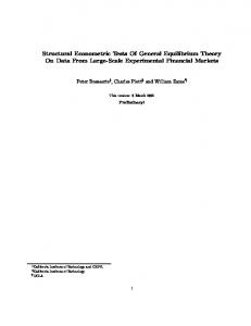
composite and steel-framed buildings in fire. In this paper the current theoretical basis of the program is very briefly outlined. Three of the Cardington fire tests, representing cases in which markedly different degrees of restraint are provided by the adjacent structure, are modelled to show how this restraint affects the behaviour within the heated zone. The effect of tensile membrane action in slabs has been suggested recently as being an important mechanism for supporting the loading and maintaining the integrity of the fire compartment at the high deflections which eventually occur as temperatures rise. In order to illustrate the influence of membrane actions and their relationship with boundary restraint, all cases have been analysed using both geometrically linear and non-linear slab elements. A series of parametric studies has been carried out as a pilot study within an investigation into the slab design parameters which allow this action to take place. 2. THEORETICAL BASIS OF THE PROGRAM In this 3-D non-linear finite element procedure which is the theoretical basis of VULCAN the composite steel-framed building are modelled as an assembly of finite beam-column, spring, shear connector and slab elements. It is assumed that the nodes of theses different types of element are defined in a common reference plane, as shown in Fig. 1. The reference plane is assumed to coincide with the mid-surface of the concrete slab element. Its location is fixed throughout the analysis. Slab elements Reference plane
z y x Concrete layers Slab node
Distributed steel layers Beam elements
Connector element
Beam node
Fig. 1. Division of composite structure into beam, slab and shear connector elements. The beam-columns are represented by 2-noded line elements. The cross-section of each element is divided into a number of segments to allow consideration of distributions of temperature, stress and strain through the cross-section. To model the characteristics of steelwork connections a 2-noded spring element of zero length, with the same nodal degrees of freedom as a beam-column element, is used. The details of the formulations of these elements and the constitutive modelling of steel at elevated temperatures have been presented previously [2, 3]. In order to model the composite slabs including their ribbed lower part a modified layered orthotropic slab element has been developed. This element is based on the
2
previously developed layered procedure [5] in which the slab elements are modelled using a layered flat shell element based on Mindlin/Reissner theory and each layer can have a different temperature and material properties. An effective stiffness model has been incorporated into the layered procedure to account for the orthotropic properties of composite slabs. The basic idea is to use a stiffness-reduction factor (or effective stiffness factor) to modify the material stiffness matrix for the properties parallel and orthogonal to the ribs. The calculation of effective stiffness factors is based on the theory of elastic beam bending and determined from the geometric dimensions of the cross-section of the composite slab. The stiffness matrix in local co-ordinates can be transformed into global co-ordinates using a standard transformation matrix. A maximum-strain failure criterion has been adopted in this model. When the principal mechanical strains at any Gauss point exceed the maximum tensile or compressive strains then cracking or crushing will occur. A smeared crack model has been used, in which cracking at any Gauss point is identified layer by layer. After the initiation of cracking in a single direction, the concrete is treated as an orthotropic material with principal axes normal and parallel to the cracking direction. Upon further loading of singly cracked concrete, if the tensile strain in the direction normal to the first set of smeared cracks exceeds the maximum tensile strain then a second set of cracks forms. After crushing concrete is assumed to lose all stiffness. The uniaxial properties of concrete and reinforcing steel at elevated temperatures which are specified in EC4 have been adopted in this model. The details of this modified layered procedure can be found in [6]. In order to model the interaction of the steel beam and the concrete slab the shear connector element has been developed to link slab and beam elements. The details of connection of the three elements are shown in Fig. 1. The shear connector element in Fig. 1 is a specialised element, which has zero length and three translational and two rotational degrees of freedom at each node. Because the shear studs prevent the relative movement of slab and beam elements in the vertical direction it is assumed that there is no relative vertical movement between their nodes. It is also assumed that common nodes of slab and beam have the same rotations. The shear connector element permits the modelling of full, partial and zero interaction at the interface between the concrete slab and the steel beam. The details of the formulation are given in [7]. The authors have recently further extended the layered procedure mentioned above to include geometric non-linearity in the modelling of reinforced concrete slabs in fire [8]. A quadrilateral 9-noded higher-order isoparametric element is used in place of the previous 4-noded geometrically linear element, and a total Lagrangian approach is adopted. In this non-linear layered procedure all previous developments in the modelling of material non-linearity are retained, including the effective stiffness modelling of ribbed composite slabs. This development is intended to enable VULCAN to model the membrane action caused by "P-∆" interaction of concrete floor slabs in fire. 3. MODELLING OF THE RESTRAINED BEAM TEST A full-scale eight-storey composite test building was constructed by BRE at its Cardington Laboratory during 1994 to resemble a modern city-centre medium-rise office development typical of current UK practice. Composite action was achieved
3
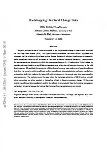
between both primary and secondary steel beams and the floor slabs using shear studs. The Restrained Beam Test was carried out by British Steel plc [9,10] on the frame in January 1995. It was the first, and the smallest, of six fire tests carried out in 1995 and 1996, and involved heating a single secondary beam and an area of the surrounding slab on the seventh floor. The major objective of this test was to study the effects of restraint from the large area of surrounding cool structure, including floor slabs, on the behaviour of the heated structure. The member tested consisted of a 305x165UB40 section spanning between columns D2 and E2, and was heated using a specially constructed gas-fired furnace along the middle 8m of its 9m length. The location of the test is shown in Fig. 2. The extent of the structure incorporated within the model is also indicated in Fig. 2, with a more detailed representation including the finite element mesh layout shown in Fig. 3. Position of BRE large compartment fire test A
9m
B
9m
C
9m
D
9m
E
9m
F
4
6m 3
9m 2
6m 1
Position of restrained beam test
Position of BS corner test
Fig. 2 Locations of the three fire tests in the Cardington test frame. In the Cardington test building the total nominal thickness of the composite slabs was 130mm, with a 75mm top continuous portion, giving effective stiffness factors of 0.72 and 0.34 parallel and perpendicular to the rib direction. The ambient-temperature material properties used in the modelling, based on tested values where these were available, were as follows: • The yield strength of steel was 308MPa for Grade 43 steel (S275) and 390MPa for Grade 50 steel (S355); • The yield strength of the steel used in the anti-crack mesh was assumed to be 460 MPa; • The elastic modulus of steel was 2.1x10⁵ MPa; • The average compressive strength of concrete test samples was 35 MPa, and this is used. A uniform floor load of 5.48kN/m2 was applied to the whole building using sand-bags, and this is assumed in the modelling. The temperature distributions across the section
4
of the steel beam and the depth of the slab are assumed to be invariant with position within the fire compartment. These temperature distributions at any time in the test are the averages of the recorded test temperature distributions at this time across the beam and slab. The maximum recorded temperatures of the bottom flange, web and top flange were 834°C, 816°C, and 764°C respectively, and the maximum recorded temperatures of the bottom and top layers of the slabs were 481°C and 129°C respectively. In order to investigate the structural behaviour of the restrained beam up to extremely high temperatures, these temperatures have been extrapolated linearly, so that the maximum temperatures of the bottom flange of the beam and bottom layer of the slab become 1005°C and 637°C respectively. The temperature of the bottom flange of the tested beam is used as the "key temperature" which is quoted in all figures. y
4.5 m
Assumed boundary line
Fire zone
2 6.0 m
1
4.5 m
E Fig. 3
x
9.0 m
F
Finite element layout adopted in the analysis of the Restrained Beam test.
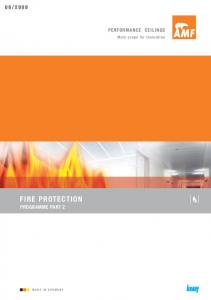
The test is modelled using geometrically linear and non-linear slab elements, and the orthotropic nature of the slabs is included in the modelling. The test results showing the variation of mid-span deflection of the heated beam against the bottom flange key temperature are given in Fig. 4, together with the analytical results. Then results shown for the geometrically linear slab element are for the complete orthotropic cross-section; in previous modelling the best agreement had been obtained by using only the upper continuous portion. It is evident that the influence of membrane action is very significant in this situation of high restraint, especially when the key temperature is higher than 500°C. The predictions of the present model, in which geometric nonlinearity of slab element is included, are in remarkably good agreement with the test results. Due to the high restraint from surrounding cool structure the second-order forces caused by geometric non-linearity in the beam and slab within the fire compartment become very significant and eventually dominate the structural behaviour. Fig. 5 shows the distributions of the two principal membrane tractions in the slab at ambient temperature. It can be seen that the slabs above the composite secondary and primary beams act very much in line with the normal engineer's assumption for the flanges of composite beams, being in compression in the spanning direction. This
5
reduces somewhat in the zones mid-way between parallel beams due to the well-known phenomenon of shear lag (see Fig. 6). Mid-span deflection (mm) 0
-100
-200
Test Geometrically non-linear slab elements
-300
Geometrically linear slab elements
-400 0
200
400
600
800
1000
1200
Temperature (°C)
Fig. 4. Comparison of predicted and measured deflections for the Restrained Beam test using geometrically linear and non-linear slab elements. Heated beam
2
1 F
E
Fig. 5 Distribution of two principal membrane tractions at 20°C for the Restrained Beam test (thick line = compression; thin line = tension).
6
At the beam-ends, which are zones of hogging action, these slab membrane tractions are in tension. In contrast, the membrane tractions within the slabs at very high temperature are presented in Fig. 7. Membrane force in x-direction (N/mm) 0 Secondary beams -50
-100
-150
-200
0
3
6
9
12
Distance from the edge in y-direction (m)
Fig. 6 Distribution of normal membrane tractions along the assumed boundary line in the y-direction at 20°C for the Restrained Beam Test.
Heated beam 2
1 E
F
Fig. 7 Distribution of two principal membrane tractions at 1000°C for the Restrained Beam test (thick line = compression; thin line = tension). It can be seen that very high compressive tractions are formed surrounding the edges of the fire compartment, and within the fire compartment the compressive tractions at the
7
edges gradually change to tensile in the central areas. The central zone of the fire compartment is subject to tensile membrane forces which are carried mainly by the anticrack mesh. If the tensile forces are large enough to cause the steel reinforcement to yield then the slabs within the fire compartment will fail, at least in terms of maintaining the integrity of the compartment. Axial Force (kN) 800 600 400 200 0 Axial force Fx
-200 -400 0
200
400
600
800
1000
1200
Temperature (°C)
Fig. 8 Predicted axial force at mid-span of tested beam for Restrained Beam test. Fig. 8 shows the change of the internal force Fx of the heated steel beam at its mid-span position as its temperatures increase. It can be seen that the beam is in tension at ambient temperature, when the steel beam is acting as the tension zone of a composite beam. As temperatures rise the steel beam heats more rapidly than the concrete slab and attempts to expand against both the cool surrounding structure and the slab itself. Due to the high restraint provided by these cooler elements the axial force in the heated beam changes rapidly from tension to compression in the initial heating stage, reaching a peak at about 350°C. On further heating, the steel’s progressive loss of strength and stiffness gradually becomes more significant than the restrained expansion, and so the axial force in the beam gradually reduces. It eventually passes into low, and almost constant, tension as the deflection becomes very high due to the weakening of the slab. At this stage the beam is acting similarly to a catenary cable of finite strength, helping to support the slab. 4. MODELLING OF THE BRITISH STEEL CORNER FIRE TEST In July 1995 a fire test (Test 3 of the British Steel series) was carried out [11,12] on a corner bay of the structure 9.98m wide by 7.57m deep. The walls of the fire compartment, shown schematically in Fig. 2, were constructed using lightweight concrete blockwork, the top of which was detached to allow free deflection of the
8
structure above. All columns and perimeter beams were wrapped with ceramic fibre, but all other structural elements were left unprotected. The test was fired using timber cribs giving an overall fire load of 45kg/m2 to produce a natural fire. During the fire test the maximum recorded atmosphere temperature in the compartment was 1028°C, which occurred after 80 minutes. Steel temperatures and structural deflections were recorded at key locations and at required intervals throughout the test, providing information for comparison with analytical results. A description of the test and comprehensive records of temperatures and deflections are given in Refs. [11, 12]. The test location, the extent of the structure incorporated within the numerical model and the finite element mesh layout are shown in Figs. 2 and 9. The material properties at ambient temperature and the uniform floor load were the same as in the Restrained Beam test. In order to rationalise the test temperature profiles of the beams and columns the following assumptions were made (see Fig. 9 for the beam positions): •
Unprotected beams B1/2, B2, BE have the same temperature distributions, in which the maximum temperatures of the bottom flange, web and top flange are 900°C, 860°C, and 800°C respectively;
•
Protected beams B1 and BF have the same temperature distributions, in which the temperatures of the bottom flange, web and top flange were 250°C, 180°C, and 110°C respectively;
•
The cross-sections of all protected columns have uniform temperature distributions with a maximum temperature of 160°C.
The average test temperature distribution through the thickness of the concrete slab was used with the maximum temperatures of bottom and top layers at 360°C and 70°C respectively. y
Assumed boundary lines
4.5m B2
2 3.0m
D11 BE
Fire zone
3.0m 1
B1/2
BF
4.5m
B1
4.5m
x
4.5m F
E
Fig. 9. Finite element layout for Corner Fire test, with locations of comparisons.
9
Again the test has been modelled using both geometrically linear and non-linear slab elements. Fig. 10 shows the test results with the predicted deflections for the mid-span (point D11) of the central secondary beam B1/2, against the bottom flange temperatures of the beam. Deflection (mm) 0
-100
-200 -300
Test
-400
Geometrically non-linear slab elements Geometrically linear slab elements
-500 0
200
400
600
800
1000
Temperature (°C)
Fig. 10 Comparison of predicted and measured deflections for the BS Corner Fire Test using geometrically linear and non-linear slab elements.
2
1 E
Fire zone
F
Fig. 11 Distribution of the principal membrane tractions at 900°C for the BS Corner Fire Test (thick line = compression; thin line = tension).
10
The distribution of the two principal membrane tractions at 900°C is shown in Fig. 11. It can be seen that when the vertical deflections were less than 300mm in which the temperatures of the steel beam were less than 700°C, there was little influence of tensile membrane action. After further increase of temperature the steel beams had lost most of their strength, and the loads above fire compartment were largely carried by the floor slab. In this corner test little restraint was provided by surrounding cool structure, and so the floor slabs within the corner bay need to be almost self equilibrating. This means that the tensile membrane forces within the central zone of the floor slab were balanced by the compression forces formed around the perimeter of the fire compartment. The load-carrying capacity of the slabs was increased significantly due to this tensile membrane action in which the anti-cracking mesh is the key component. This phenomenon is confirmed visually in Fig. 11. The area of steel reinforcing mesh used in the concrete slabs of the Cardington tests was 142mm2/m. In order to demonstrate the effect of reinforcement on the structural behaviour two fictitious reinforcing meshes, with half and double the actual area, were employed for comparison, and the geometrically non-linear slab element was used. The predictions and test results for the vertical deflection at the mid-span (D11) of secondary beam B1/2 are shown in Fig. 12. Deflection (mm) 0
-150
Test
-300
2
Mesh 71 mm /m 2
Mesh 142 mm /m -450
-600
2
Mesh 284 mm /m
0
200
400 600 Temperature (°C)
800
1000
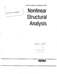
Fig. 12 Comparison of predicted deflections at D11 with different areas of reinforcement against test results for the BS Corner Fire Test. Fig. 13 shows the cracking patterns of the bottom and top floor slab layers at 500 °C. It can be seen that at this stage the concrete was subjected to intensive cracking, so that the tensile membrane forces within the floor slabs were mainly carried by the steel mesh. Hence the load capacity of concrete slabs depends strongly on the reinforcement area and strength. As the temperatures of the steel beams increase their strength and
11
stiffness is decreasing so that the influence of steel reinforcement becomes more and more significant. In an extreme situation, when slabs are subjected very large deflections, the reinforcement will become a key element in maintaining the integrity of the structure, and if the reinforcement fails this may initiate a major structural failure. Ensuring that fracture of slabs does not occur may necessitate either higher reinforcement ratios, higher ductility or placement of the mesh further from the heated surface of the concrete. TOP LAYER
2 One crack Two cracks Crushing
1 Fire zone BOTTOM LAYER
2
1 Fire zone
E
F
Fig. 13 Predicted crack patterns of the top and bottom layers of the floor slab at 500°C in the BS Corner Fire Test. 5. MODELLING OF BRE LARGE COMPARTMENT FIRE TEST In April 1996 BRE carried out their second fire test [13] on the Cardington Test Frame, in a large compartment between the second and third floors. This extended across the full width of the building, between grid-line A and a line 0.5m from grid-line C (see Fig. 2). This is considered to be the largest fully instrumented fire test which has taken place to date, covering an area of 340m2. A fire load of 40kg/m2 of wood was provided by timber cribs. All the internal steel beams were unprotected, but the columns were
12
protected over their full height, including their connections. The maximum recorded atmospheric and steelwork temperatures were 763°C and 691°C, respectively. The average maximum temperature of the slab soffit was about 260°C. The extent of the structure incorporated within the numerical model is shown in Fig. 2, and more detail, together with the finite element mesh layout adopted, is shown in Fig. 14. y
Assumed symmetry line B14
Assumed boundary line
D32 B4
B8 B10
4.5m
B7
B13 B3
2
Fire zone
3m
D39 B9
3m
B12
B11 D23 B6
B2 B1
B5
1 A
4.5m
4.5m
4.5m
4.5m
B
9m C
D
x
Fig. 14 Finite element layout adopted in the analysis of the BRE Large Compartment Fire Test, together with the locations of comparisons. In the analysis the rotational and horizontal movements perpendicular to the assumed symmetry and boundary lines were fixed. The ambient-temperature material properties assumed were the same as for the corner test, and a uniform floor load of 5.48kN/m2 was again assumed. In order to investigate the structural behaviour of this large fire test up to extremely high temperatures the measured temperatures have been extrapolated linearly, so that the following assumptions have been made for the modelling: •
Beams B2, B3, B4, B6, B7, B8, B10, B11 had identical temperature distributions, with the maximum temperatures of the bottom flange, web and top flange being 1000°C, 957°C and 885°C respectively;
•
Beams B1, B5, B9, B12, B13 and B14 had the same temperature distributions, with the maximum temperatures of the bottom flange, web and top flange being 640°C, 640°C and 567°C respectively;
•
The cross-sections of all columns inside or surrounding the fire compartment had uniform temperature at any time, with a maximum temperature of 92°C;
•
The average temperature distribution through the thickness of the concrete slab was used, with the maximum temperatures of bottom and top layers being taken as 366°C and 106°C respectively.
In order to demonstrate the influence of membrane action the test was modelled using both geometrically linear and non-linear slab elements. The comparisons between the predicted and test results for vertical deflections taken at the 3 key positions shown in Fig. 14 are plotted in Figs. 15-17.
13
Deflection (mm) 0 -200 POSITION D32 -400 Test -600
Geometrically non-linear slab element
-800
Geometrically linear slab
-1000 0
200
400 600 Temperature (°C)
800
1000
Fig. 15 Comparison of predicted and measured deflections at position D32 for BRE Large Compartment Fire Test using geometrically linear and non-linear slab elements. Deflection (mm) 0
-200 POSITION D39 -400
Test
-600
Geometrically non-linear slab elements Geometrically linear slab elements
-800 0
200
400 600 Temperature (°C)
800
1000
Fig. 16 Comparison of predicted and measured deflections at position D39 for BRE Large Compartment Fire Test using geometrically linear and non-linear slab elements.
14
Deflection (mm) 0 -50 -100
POSITION D23
-150
Test
-200
Geometrically non-linear slab elements
-250
Geometrically linear slab elements
-300
0
200
400 600 Temperature (°C)
800
1000
Fig. 17 Comparison of predicted and measured deflections at position D23 for BRE Large Compartment Fire Test using geometrically linear and non-linear slab elements. Fig. 18 shows the predicted distribution of membrane tractions at a steel key temperature of 1000°C, and the deflection profile of the composite slab is shown in Fig. 19 at the same temperature, including the cracking patterns of the top concrete layer.
Fire zone
2
1 A
B
C
Fig. 18 Distribution of two principal membrane tractions at 1000°C for BRE Large Compartment Fire Test (thick line = compression; thin line = tension).
15
D
It can be seen from Figs. 15-17 that the predictions are in good agreement with test results at positions D39 and D23. There are some discrepancies concerning position D32, for which the predictions are in good agreement with test results up to 600°C, beyond which the program produces less deflection than the actual test data. In this test, because of the large amount of instrumentation the sand-bags used to add imposed load had to be moved in some locations, so that a fully uniform floor load could not really be guaranteed. With such a deep fire compartment, ventilated at both sides, it is also impossible to be certain that the heating was uniform at any time or across the whole area. In spite of these uncertainties the program produces very reasonable predictions compared with the test results for such a large-scale fire test. From Fig. 15 it can be seen that the influence of geometric non-linearity of the slab elements is small. The reason for this is that the floor slab essentially deforms in single curvature in the region of position D32 (see Fig. 19). The restraint provided by some structural bracing in the stair-well and the atrium at the ends of the compartment was ignored in the modelling. Hence relatively small tensile membrane forces are generated within the slabs above the fire compartment. Fire zone
Fig. 19 Deflection profiles at 1000°C for BRE Large Compartment Fire Test, with cracking patterns of top layer of floor slab. Comparing the results for this test with those presented in Figs. 16-17 some effect of geometric non-linearity is apparent, especially when the key temperatures are above 800°C and the deflections of primary beam B11 are increasing sharply. At this stage the floor slabs at positions D23 and D39 are forced to some extent to deform in double curvature, and thus the influence of membrane action becomes more significant. 6. CONCLUSIONS The basic features of purpose-written computer program, VULCAN developed at the University of Sheffield, have been outlined in this paper. The program has been used to model the structural behaviour of three full-scale fire tests carried out by British Steel
16
plc (now Corus Group plc) and BRE on the Cardington composite test frame. From this study some conclusions can be drawn as follows: •
VULCAN can predict the structural behaviour of a composite steel-framed building subjected to fire with quite reasonable accuracy. The program is a useful tool to perform intensive parametric studies aimed at a deeper understanding of the structural behaviour of such structures under fire attack.
•
When the temperatures of steel beams are less than 300-400°C the influence of the concrete slabs on the structural behaviour of a composite building is small, but when temperatures are above 500°C the effect of the slab increases greatly. It then becomes very important to model concrete slabs correctly. The influence of membrane action cannot be ignored, particularly when the fire compartment is subject to high restraint because it is surrounded by cool, stiff structure.
•
When the deflections of floor slabs become large the influence of tension membrane action in the slabs can become important in supporting the slab loading. Whether this is capable of preventing final fracture of the slabs depends mainly on the properties of the steel reinforcement used and the degree to which it is insulated from temperature rise by its concrete cover, even if this is cracked.
•
It has been seen that tensile membrane action is not necessarily dependent on inplane restraint, since the mid-slab tensions can be balanced by peripheral compressions, provided that the slab is forced to deform in double curvature because of vertical support to its edges. The benefit of tensile membrane action to the loadcarrying capacity of the floor slabs is minimised when they deform in single curvature. If this is the case, then slabs may probably undergo much higher deflections before the tractions reach critical values at which fracture occurs. In these circumstances the relative movement of the column-ends may become unacceptable, or unsafe, before there is fracture of slabs
These three full-scale fire tests span a wide range in terms of the restraint to horizontal movement of slabs or beams. It is apparent that the slab reinforcement, which has been employed mainly for control of cracking during the curing process and may not be subject to any structural calculation in design, may be vitally important in ensuring integrity when a building is subject to high deflection in the fire limit state. Design of this reinforcement for tensile membrane action in fire may be the price to be paid for design processes based on the real performance of such systems rather than that of isolated elements. Acknowledgement: The authors gratefully acknowledge the support of the Engineering and Physical Sciences Research Council of Great Britain under grant GR/M99194. REFERENCES [1] European Committee for Standardisation, " Eurocode 4, Design of composite steel and concrete structures, Part 1.2: Structural fire design (Draft)", Commission of the European Communities, Brussels, (1992). [2] Najjar, S.R. and Burgess, I.W., "A non-linear analysis for three-dimensional steel frames in fire conditions", Engineering Structures, 18 (1), (1996) pp77-89.
17
[3] Bailey, C.G., Burgess, I.W. and Plank R.J., "Computer simulation of a full-scale structural fire test", The Structural Engineer, 74(6), (1996) pp93-100. [4] Huang, Z., Burgess, I.W. and Plank, R.J., "Three-dimensional analysis of composite steel-framed buildings in fire", J. Struct. Eng. ASCE, 126(3), (2000) pp389-397. [5] Huang, Z., Burgess, I.W. and Plank, R.J., "Non-linear analysis of reinforced concrete slabs subjected to fire", ACI Structural Journal, 96(1), (1999) pp127-135. [6] Huang, Z., Burgess, I.W. and Plank, R.J., "Effective stiffness modelling of composite concrete slabs in fire", Engineering Structures, 22(9), (2000) pp11331144. [7] Huang, Z., Burgess, I.W. and Plank, R.J., "Influence of shear connectors on the behaviour of composite steel-framed buildings in fire", J. Construct. Steel Research, 51(3), (1999) pp219-237. [8] Huang, Z., Burgess, I.W. and Plank, R.J., "Non-linear layered procedure for modelling of concrete slabs in fire", Research Report DCSE/2000/F/1, Department of Civil and Structural Engineering, The University of Sheffield, (2000). [9] Bentley, P.K., Shaw, D. and Tomlinson, I., "ECSC Project: Behaviour of a multistorey steel framed building subjected to natural fires. Test 1: Restrained beam, Data files: Temperature measurements", Report S423/1/Part T1, Swinden Technology Centre, British Steel plc, Rotherham, UK, (1995). [10] Bentley, P.K., Shaw, D. and Tomlinson, I., "ECSC Project: Behaviour of a multistorey steel framed building subjected to natural fires. Test 1: Restrained beam, Data files: Deflection measurements", Report S423/1/Part D1, Swinden Technology Centre, British Steel plc, Rotherham, UK, (1995). [11] Bann M. S., Bentley P.K., Shaw D. and Tomlinson I., “ECSC Project: Behaviour of a multi-storey steel framed building subjected to natural fires. Test 3: Corner compartment, Data files: Temperature measurements”, Report S423/1/Part T1, Swinden Technology Centre, British Steel plc, South Yorkshire, (1995). [12] Bentley, P.K., Shaw, D. & Tomlinson, L., “ECSC Project: Behaviour of a multistorey steel framed building subjected to natural fires. Test 3: Corner compartment. Data files: Deflection/Displacement measurements”, Report S423/3/Part D1, Swinden Technology Centre, British Steel plc, Rotherham, UK, (1996). [13] Lennon T., “Cardington fire tests: instrumentation locations for large compartment fire test”, Report N100/95, Building Research Establishment, Watford, (1996).
18