triple graph grammar approach [17] allow for the specification and application ... Thus, their APIs and, therefore, their metamodels are rather generic on the one.
Non-materialized Model View Specification with Triple Graph Grammars Johannes Jakob, Alexander K¨onigs, and Andy Sch¨ urr Real-time Systems Lab Darmstadt University of Technology D-64283 Darmstadt, Germany {jakob|koenigs|schuerr}@es.tu-darmstadt.de www.es.tu-darmstadt.de
Abstract. Model-based tool data transformation and integration are crucial tasks in software and system development relying on modeldriven development (MDD). Since the tool-specific meta models of the involved system development tools are often too generic and lack the desired level of abstraction, it is inappropriate to specify model transformation and integration rules on top of them. Domain-specific views on tool-specific meta models are needed which provide meaningful information on a higher level of abstraction. Current approaches usually consider a view as a separate model which has to be kept consistent with the tool’s model and, thus, duplicate the data. In this paper we discuss different implementations of our declarative view specification approach called VTGG that are based on modified triple graph grammars. As a result we come up with an implementation with non-materialized views that avoids the duplication of data.
1
Introduction
Typically, software development and system engineering projects involve lots of tools each specialized in a number of development phases as requirements elicitation, system modeling, coding, testing, etc. Manually keeping the data stored in these tools consistent is time-consuming and error-prone. Thus, there is a need for automatic data transformation and integration support. Model transformations are a powerful way to realize the needed support. Current approaches including OMG’s Query/View/Transformation (QVT) [20] standard and our own triple graph grammar approach [17] allow for the specification and application of model transformation or model integration rules based on the metamodels of the considered tools. Most tools are designed for multiple types of projects. Thus, their APIs and, therefore, their metamodels are rather generic on the one hand. On the other hand these metamodels reflect tool-specific and technical details which usually results in quite complex APIs. This makes it difficult and intricate to specify model transformation or model integration rules based on tool metamodels. Therefore, it is desirable to define views on tool metamodels in order to add project-specific information on the one hand and to suppress technical details on the other hand. In this paper we focus on the latter issue.
2
Johannes Jakob, Alexander K¨ onigs, and Andy Sch¨ urr
Current model transformation and integration approaches either disregard views at all or realize them as separate models that are kept consistent with the viewed model by applying common model transformation techniques. This results in an awkward duplication of data. In contrast, we want to realize logical views as functional interface adapter layers that do not replicate any data at all. To summarize, we propose the following list of requirements that, in our opinion, should be supported by a view specification approach: – Abstraction of tool-specific data, like mapping of several objects or links to one object or link (includes the mapping of links to objects). – Domain-specific modeling; for instance, to define project class specific constraints on and adaption for tool metamodels. – Views on top of views to support different abstraction levels. – Multiple views for one base model, for example, to realize viewpoint approaches. – Metamodel based scheme definition of view and tool data structures. – Avoiding the duplication of data; view creation should not result in coexisting view and tool data representations. – Updateable views. Updates should be incrementally propagated in both directions, between a view and its base model. In this paper we introduce a new view specification approach for MDD that fulfills the listed requirements. The paper is based on our initial ideas outlined in [14]. The main enhancements to the latter are the usage of parameters for attribute value assignments and the definition of an implementation metamodel on which the implementation of the operational rules are based. In Section 2 we discuss related view specification approaches. Thereafter, in Section 3 we present a running example that we use for illustration purposes in the following. In Section 4 we introduce our declarative view specification approach called VTGGs. The implementation of view specifications by applying the class adapter pattern of the Gang of Four [8] is described in Section 5. Finally, Section 6 concludes this paper, discusses open issues, and future work.
2
Related Work
Within the context of view specification, we have to distinguish different kinds of views. In the following we distinguish between three main categories. The first category describes approaches that can be classified as visual representations of models. Meta-case tools like Pounamu [25] or MetaEdit [18] use “model view” as a short-hand for visualization of a model. In the same way the MViews/JViews [9, 10] approach for the construction of design environments supports a transformation approach that generates visual representations. AToM3 is another approach that is based on metamodeling and a special form of triple graph grammars to generate environments for visual languages (VLs) supporting multiple-views [12, 13, 4]. It mainly supports propagation of updates from a base model to its materialized views and relies on a single metamodel for
Lecture Notes in Computer Science
3
all views. The animated simulation of a model’s behavior with GenGED [6, 7] proposes the use of animation views instead of simulating the model behavior. Thus, GenGED defines a view as an incomplete specification of a system like a VL model that is part of a larger VL model. The relation between the view and the larger system is captured by graph transformations in the form of materialized views. For our approach, a visual representation is out of scope. We aim at logical model views that are again “models” and not just visualizations. The second category comprises approaches dealing with logical views. Naturally, in respect of having a self-contained view model, this part includes “regular” model transformation approaches like AGG, VIATRA2, VMTS that are compared in [5]. Of course, these approaches have other intentions, but they can also be utilized for view specification purposes with the weakness of generating materialized views. The OMG’s QVT standard [20] explicitly excludes in its current version the part of view specification. However, as far as we know they plan a definition of view specification that is also based on model transformation. The viewpoint-oriented approach of [24] also provides an own model transformation language called ArchiMate with an underlying repository in which the models and their views are made persistent. A fully materialized view is one of the main disadvantages of all these related approaches, which results in an intricate duplication of data together with the inherent view update problem. Another drawback of the approaches above is the disability of mapping view associations onto base model objects (or vice versa). Views in the world of databases either belong to the second category of logical views or consitute a third category. Usually, database views are defined as query results for relational databases. Incremental propagation of updates is often not supported and views for object-oriented data models is usually out-of-scope. For a more detailed discussion of research related to database views the reader is referred to [14]. As far as we can estimate, there are no tools or approaches that fulfill our requirements of view specification.
3
Running Example
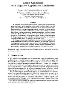
In this section we present a running example that we use throughout this paper. On the one hand we aim at integrating the data of a model-based software development project stored in quite a number of different tools. On the other hand we aim at manipulating the data of a single tool by applying model transformation rules. Since the tools’ metamodels are too generic and, thus, offer too little project-specific abstraction on the one hand and reflect unnecessary tool-specific details on the other hand it is desirable to specify the model integration and transformation rules on a higher abstraction level. This abstraction can be realized by creating views on the tools’ data as shown in Figure 1a. The depicted tool adapter provides a standard compliant interface (e.g. Java Metadata Interface (JMI) [15]) on the tool’s data by adapting its proprietary tool interfaces (e.g. APIs). Thereby, the adapter reflects the internal data struc-
4
Johannes Jakob, Alexander K¨ onigs, and Andy Sch¨ urr a)
b) VMM
TMM
transformation
Block inA 0..1 inB 0..1
view update
VTGG
block 1 hasInPorts
Const value : Integer outB 0..1
tool adapter tool update (event?)
description : String
connectsB
tool update (event?)
view update
connectsA
view adapter
type : String text : String valueAtt : Integer
Comp
BinComp
outA 0..1
{view}
Comp {map} Block Const {map} Block BinComp {map} Block SumComp {map} Block ProdComp {map} Block connectsA {map} Line connectsB {map} Line
{xor}
block 1 hasOutPorts
inPort 0..* {model}
outPort 0..* OutPort
InPort number : Integer target 0..1
source 0..1
inPortToLine
tool
outPortToLine
line 0..1
e.g. requirement tool,...
SumComp
ProdComp
line 0..1 Line
Fig. 1. a. Adapter layers, b. Metamodels of view, correspondence graph, and tool
ture of the tool, which correspond to the tool-specific metamodel (TMM). On top of these tool-specific interfaces we specify view adapters which provide read and write access to the tool’s data through view-specific interfaces reflecting the view-specific metamodels (VMMs)1 . Please note that we will introduce later on an implementation of this 3-layer architecture that avoids duplication of data by translating all read/write operations on one layer into read/write operations of the next lower layer. In the running example we want to perform a model transformfation on a Matlab/Simulink2 model (cf. Figure 2a). Two Constant blocks carrying the values 1 and 2 respectively are used as input for a Sum block which calculates the sum of its inputs. The result as well as a third Constant block carrying the value 2 are used as input for a Product block which returns the product of its inputs. We aim at specifying a model transformation rule that substitutes a Sum block that has two Constant blocks as input by a single Constant block whose value is set to the sum of the values of the existing Constant blocks. Figure 2b shows the abstract representation of the Matlab/Simulink model as an object graph (a model according to OMG’s metamodeling approach). On the one hand the object graph contains undesirable tool-specific details as the Line, InPort, or OutPort objects for instance. On the other hand the object graph lacks preferable abstract information as dedicated Constant, Sum, and Product objects instead of general Block objects carrying type attributes. The reason for these deficiencies can be found in the simplified tool-specific graph schema (metamodel; cf. Figure 1b on the right-hand side) to which the object graph complies. The graph schema states that a Matlab/Simulink model basically consists of Blocks that carry a type and a text attribute. Furthermore, each Block is provided with an arbitrary number of InPorts and OutPorts. For identifica1
2
In principle we can specify further view adapters on top of existing view adapters in order to realize different levels of abstraction. http://www.mathworks.com
Lecture Notes in Computer Science a)
5
b) b1:Block type = “Const“ valueAtt = 1
b3:Block
i1:InPort
type = “SumComp“
i2:InPort o1:OutPort
o3:OutPort
l1:Line
l3:Line
Const
b2:Block SumComp Const
type = “Const“ valueAtt = 2
b4:Block type = “Const“ valueAtt = 2
ProdComp
o2:OutPort Const
l2:Line
c)
d)
i3:InPort
b5:Block
i4:InPort
type = “ProdComp“
o4:OutPort
o5:OutPort
l4:Line
l5:Line
substituteSumComp(SumComp s) {
c1:Const
connectsA
c1:Const s:SumComp
c2:Const
p:ProdComp
c2:Const
connectsB
value += c1.value
c2:Const
connectsA
s:SumComp connectsA
b:BinComp
}
Fig. 2. a. Matlab/Simulink model, b. Tool-specific object graph, c. View-specific object graph, d. Model transformation rule
tion purposes each InPort carries a number attribute. In- and OutPorts can be connected by Lines. We aim at an object graph without these deficiencies as depicted in Figure 2c. This graph consists of dedicated Constant, Sum, and Product objects and omits the low level Line, InPort, and OutPort objects. Therefore, it provides the desired level of abstraction. The graph complies to the graph schema shown in Figure 1b on the left-hand side. According to this schema an object graph consists of components Comp. Components either are binary components BinComps or constants Const. Each BinComp can be connected with up to two Comps through its input links inA and inB. Correspondingly, a Comp can be connected with up to one BinComp through either output port outA or outB. This is expressed by the attached {XOR} constraint. Finally, a BinComp either can be a sum component SumComp or a product component ProdComp. Based on the view metamodel, we can easily specify the model transformation rule as depicted in Figure 2d3 . We denote the model transformation rule as a graph rewriting rule according to the Story Driven Modeling (SDM) language introduced in [26]. The method substituteSumComp is provided with an input parameter s of type SumComp. The graph transformation rule checks whether s is connected to two Const blocks c1 and c2 as input and an BinComp block b as output. If this pattern is matched on the regarded model the rule destroys 3
Due to the consistency of view and tool data, dangling edges are not possible.
6
Johannes Jakob, Alexander K¨ onigs, and Andy Sch¨ urr
c1 and s as well as their links of type connectsA and connectsB respectively to connected objects. Furthermore, the rule changes the value of the attribute value of c2 to the sum of the value of c1 and c2. Finally, it replaces the link of type connectsA (or connectsB) between s and b by a link of type connectsA (or connectsB) between c2 and b. The same graph transformation rule specified based on Simulink’s tool-specific metamodel is considerably more complex, and, therefore, less understandable. Due to lack of space we have to omit this rule. In order to realize the object graph from Figure 2b as a view on the graph from Figure 2b we have to map them to each other. We declare the needed mapping dependencies in the graph schema (cf. Figure 1b in the middle - metamodel of correspondence graph). For clarity reasons we introduce these dependencies only textually. In fact these dependencies are declared visually as well. Besides the mapping dependencies we need rules that describe which objects of the one graph are actually mapped to which objects of the other graph. To this end we rely on the triple graph grammar approach as pointed out in the following section.
4
VTGGs
In this section we describe the basics of our model view specification approach called VTGGs. VTGGs are a special kind of triple graph grammars (TGGs). TGGs have been introduced in [22] about ten years ago. Hitherto, they only have been implemented in prototypical ways [2, 3, 11, 16]. Currently, we are working on an implementation [17] that adopts recent OMG standards as the Meta Object Facility (MOF) 2.0 [19] and Query/View/Transformation (QVT). Thereby, MOF 2.0 plays the role of a graph schema definition language, whereas QVT acts as a model integration specification language. Basically, a TGG is a regular graph grammar consisting of a set of graph rewriting rules taking the empty graph as the axiom. Each graph that has been derived by applying triple graph grammar rules can be divided into three related subgraphs. Two subgraphs represent a pair of corresponding graphs, whereas the third keeps track of correspondences by means of traceability relationships. In our context one graph represents the toolspecific object structure. The second graph represents the corresponding viewspecific object structure. Finally, the third graph keeps track of the mapping dependencies between the first and the second graph. It is one of the main advantages and, thus, a reason for using TGGs, that a set of regular graph rewriting rules implementing model integration tasks as forward transformation, backward transformation, traceability link creation, change propagation, and so on, can be automatically derived from each triple graph grammar rule. For more details the reader is referred to [17]. Regular TGGs are used for model integration and transformation purposes. Thereby, changes on one model are propagated to the other model by applying forward and backward model transformation rules. In the context of view creation we want to materialize neither the view nor the correspondence graph. They should only exist virtually. In the following we present how we modify
Lecture Notes in Computer Science
7
TGGs to this end. Thereby, we refer to the running example we introduced in Section 3. Particularly, we come up with a new rule derivation strategy that derives a set of view implementing graph rewriting rules from a declarative view specification. According to regular TGGs, the creation of new objects or links are denotated with the {new} tag. The mapping relationships from virtually existing VMM objects (left-hand side) to really existing TMM objects (right-hand side) are modeled as links between objects combined with the tag {new}4 . Furthermore, we modify TGGs as follows. First of all, we allow that the creation of a link in one graph simultaneously creates a subgraph in the other graph. Additionally, a VTGG rule may only create one new object or link on the view side. Otherwise it would be very difficult to unambiguously propagate changes on the view to the tool model, i.e. to translate declarative VMM rules into operational TMM rules automatically.
a)
b) connectsA(Comp c, BinComp b) {
newSumComp(String desc) { view border
{new} s : PMM::SumComp
{new} {map}
view border
{new} b : TMM::Block
{map}
type := "SumComp" text := desc
description : = desc
o : TMM::OutPort
c : PMM::Comp {new} {new} {new}
{new}
{new}
i1 : TMM::InPort
{new} i2 : TMM::InPort
number := 1
number : = 2
b1 : TMM::Block
{new}
{new} connectsA
l : TMM::Line {new}
{new}
i1 : TMM::InPort
b : PMM::BinComp {map}
o : TMM::OutPort
number == 1
b2 : TMM::Block }
}
Fig. 3. Examples of declarative VTGG rules
Figure 3 depicts examples of declarative VTGG rules. Both rules describe the simultaneous evolution of the view and the tool object graph. The rule from Figure 3a simultaneously adds a new SumComp object s to the view and a new Block object b to the tool graph. Moreover, this rule adds secondary objects InPort i1, InPort i2, and OutPort o to the tool graph (to match the tool specific structure) and connects them with b. The rule is provided with an input parameter desc of type String which is used to set the attributes description of s and text of b5 . The value of the type attribute of b is set to 4
5
Normally, the mapping dependencies are represented as dedicated objects in declarative rules. We omit these objects for the sake of clarity. In former TGG papers OCL constraints have been used for attribute assignments. It’s part of ongoing research that this is superseded by input parameters.
8
Johannes Jakob, Alexander K¨ onigs, and Andy Sch¨ urr
"SumComp". The values of the number attributes of i1 and i2 are set to 1 and 2, respectively. Finally, s and b are linked by a new mapping dependency to reflect their correspondence. Rule 3b depicts a rule that is an enhancement of hitherto existing TGG rules. It is provided with two input parameters Comp c and BinComp b and connects both objects on the view side by a new connectsA link. Simultaneously, the rule connects the OutPort o of the Block b1 that corresponds to c with the InPort i1 of the Block b2 that corresponds to b with a new Line l object on the tool side. Thereby, the rule matches if the number attribute of InPort i1 has been set to 1. In the same way, the rule for adding a new link of association connectsB matches if the number attribute of an InPort instance has been set to 2. Rules that create new Const and ProdComp blocks on the view side look similar to rule 3a. The entire set of rules enables us to simultaneously create the view and tool object graphs from Figure 2 as well as their mapping dependencies. Actually, the simultaneous evolution of both object graphs is not intended. Instead, we want to manipulate a virtually existing view on the tool graph. Therefore, we derive regular graph rewriting rules based on Fujaba SDM diagrams [23, 26]. These rules implement basic operations (e.g. creation and deletion of objects and links, navigating on links, manipulating attribute values) on the view by translating them into corresponding operations on the underlying TMM.
5
Implementation
Basically, we have three alternatives how to realize views based on the declarative view specification we introduced in the preceding section. First of all, we can use regular model integration/graph transformation approaches. That means that we realize the view as a fully materialized model (graph) by applying a model-to-model integration between tool and view model. This approach suffers from the fact that we duplicate the number of graph objects as well as the whole data (e.g. attribute values) stored in the tool. Furthermore, changes on the tool model must be propagated to the materialized view. For this purpose a regarded tool’s API must offer event notification mechanisms that are not (yet) supported by a majority of system engineering tools. A better solution is the view implementation based on the object adapter pattern [8]. This means that we still duplicate the number of graph objects but do not replicate the tool’s data anymore. Rather, queries on attributes on the view level are delegated to the tool level. The most elegant solution is the application of the class adapter pattern [8]. This results in having only one single graph, the resulting view adapter, whose objects implement the view interfaces as well as the tool interfaces6 . Thereby, we even avoid the duplication of graph objects and do not have to propagate tool model modifications to a materialized view. Since we want to adopt the latest OMG standards such as MOF 2.0 and plan to implement our approach as part of the MOFLON [21] project which is written in Java, it is appropriate to rely on Sun’s JMI specification for defining the 6
Calls to the view interface are internally translated into calls to the tool interface.
Lecture Notes in Computer Science
a) project side (view side)
view border
«Interface» IJMI_SumCompClass
tool side «Interface» IJMI_InPortClass
«Interface» IJMI_BlockClass
contains
contains
«Interface» IJMI_SumComp
«Interface» IJMI_OutPortClass
contains
contains
«Interface» IJMI_Block
«Interface» IJMI_InPort
«Interface» IJMI_OutPort
Implementation border VTGG_SumCompClass
BlockClass
contains
contains VTGG_SumComp
InPortClass
OutPortClass
contains
contains
Block
InPort
OutPort
VTGG_InPort hasInPort hasOutPort
VTGG_OutPort
b)
project side (view side)
view border
tool side
«Interface» IJMI_LineClass
contains «Interface» IJMI_ConnectsA
«Interface» IJMI_Line
«Interface» IJMI_InPort
«Interface» IJMI_OutPort
InPort
OutPort
Implementation border LineClass
contains VTGG_ConnectsA
Line
inPortToLine outPortToLine
Fig. 4. Parts of the implementation metamodel
c) JMI - Proxies, Instances, Associations 1
h
Fi tA
E d
0 *
9
10
Johannes Jakob, Alexander K¨ onigs, and Andy Sch¨ urr
view and tool Java interfaces. According to JMI each class in a MOF-compliant class diagram is translated into two Java interfaces. The first interface represents instances of the regarded class and provides among others methods for querying and manipulating their attribute values. The second interface is called the proxy which allows for the creation of new instances and keeps track of the set of already existing instances. Furthermore, each association in a MOF-compliant class diagram is translated into one Java interface. This interface represents a singleton7 which keeps track of linked objects and provides query and manipulation methods on the internally maintained link set. 5.1
Implementation metamodel
In order to realize our view specification approach we have to translate the view and the tool metamodels into JMI-compliant Java interfaces and come up with an implementation of them. We assume that the tool’s metamodel has already been translated into JMI interfaces and implemented as an adapter to the tool’s API beforehand [1]. Using our MOFLON framework we can automatically generate the needed JMI interfaces for the view metamodel. As pointed out above we want to implement the resulting interfaces as class adapters [8]. Basically, a class adapter maps a desired interface (e.g. view interface) to an existing interface (e.g. tool interface). To this end the class adapter inherits from an implementation of the existing tool JMI interface. It implements the desired interface by internally translating calls to the desired interface into calls to the inherited implementation. Figure 4 depicts parts of the implementation metamodel that results from the JMI interface generation8 . Figure 4a shows the part of the metamodel which deals with the declaration of the VTGG SumComp class adapter that represents the mapping of a SumComp object on the view side to a Block object on the tool side. The top of the figure depicts the JMI interfaces, the bottom shows their corresponding implementations. The interfaces as well as the implementation of JMI proxy classes are gray. The left-hand side of the figure shows the interfaces and implementations of the view side, the right-hand side represents the tool side. On the tool side there are interfaces and implementations for the tool-specific classes Block, InPort, and OutPort as well as their corresponding proxies. According to the class adapter pattern VTGG SumComp implements the interface of IJMI SumComp and inherits from the Block implementation. Therefore, a single instance of VTGG SumComp simultaneously represents an instance of IJMI SumComp as well as of Block without replicating the data. VTGG SumComp realizes the IJMI SumComp interfaces by delegating method calls to the inherited Block implementation. For delegation purposes and to support a complete tool adapter, secondary objects on tool side are inherited by utility classes on view side (e.g. VTGG InPort). 7 8
There exists at most one instance at runtime. It’s just an elaborated scheme that describes the implementation of operational rules. So, it is not a substitute for the VTGG schema (cf. Figure 1b).
Lecture Notes in Computer Science
11
Correspondingly, Figure 4b introduces the VTGG ConnectsA class adapter. This class adapter implements the JMI interface of the connectsA association on the view side and inherits from the proxy of Line since connectsA and LineClass represent singletons that internally keep track of links and Line instances, respectively. 5.2
Derived graph rewriting rules
a)
b)
c)
VTGG_SumComp() {
setDescription(String desc) {
String getDescription() {
this type:= “SumComp“
return text;
hasInPorts
hasOutPorts
hasInPorts
i1 : TMM::InPort
i2 : TMM::InPort
number = 1
number = 2
}
this
}
description text:=desc
o : TMM::OutPort
}
}
Fig. 5. a. VTGG SumComp constructor, b. Write attribute operation, c. Read attribute operation
We automatically generate implementations of the JMI interfaces by deriving regular graph rewriting rules from our declarative triple graph grammar rules from Section 4, which in turn are automatically translated into executable Java code by our MOFLON framework. Thus, the derived graph rewriting rules represent the methods that are declared by the JMI interfaces. Figure 5 gives examples of such derived regular graph rewriting rules for VTGG SumComp that correspond to the declarative rule from Figure 3a. Figure 5a depicts the constructor of VTGG SumComp which is invoked by the corresponding create method of the proxy VTGG SumCompClass. According to the declarative rule from Figure 3a the constructor additionally creates secondary objects i1, i2 of type InPort, and o of type OutPort and sets their attribute values. Secondary objects are objects that are only visible on the tool side and have no representation on the view side. Rule 5b illustrates the implementation of the method setDescription from the IJMI SumComp interface. The rule sets the value of the text attribute which has been inherited from the Block implementation to the value of the input parameter desc. The implementation of the method getDescription from the IJMI SumComp interface is shown in Figure 5c. This rule just returns the value of the Block’s attribute text. In general, an attribute reading operation requires navigation on secondary tool objects resulting in more complex rules.
12
Johannes Jakob, Alexander K¨ onigs, and Andy Sch¨ urr
a)
b)
add(IJMI_BinComp _inA, IJMI_Comp _outA) {
local_inA:= (IJMI_Block) _inA
IJMI_Comp getOutA(IJMI_Comp _inA) {
local_inA:= (IJMI_Block) _inA
local_outA:= (IJMI_Block) _outA
hasInPorts i:TMM::InPort
i:TMM::InPort
o:TMM::OutPort
inPortToLine
hasOutPorts o:TMM::OutPort
number == 1
number == 1
b:TMM::Block
hasInPorts
hasOutPorts
outPortToLine
inPortToLine
outPortToLine
l:TMM::Line
l:TMM::Line
return (IJMI_BinComp) b; }
}
Fig. 6. a. Add new VTGG ConnectsA link operation, b. Navigate link operation
Figure 6 illustrates some of the methods of VTGG ConnectsA that are derived from the declarative rule in Figure 3b. The rule from Figure 6a represents the add method of the IJMI ConnectsA interface. The rule is provided with two input parameters inA of type IJMI BinComp and outA of type IJMI Comp which are supposed to be linked to each other. Internally, the rule casts the input parameters to IJMI Block. This may be done since the view JMI interfaces are implemented by our VTGG class adapters which implement the tool JMI interfaces as well. This has to be done in order to access the corresponding Inand OutPort objects on the tool side. Both Port objects are then linked to a new Line object on the tool side that represents the desired association link on the view side. Similarly, the rule 6b returns the IJMI Comp object that is connected to the given IJMI BinComp inA object by a connectsA link. Again the rule internally casts the input parameter for the same reasons mentioned above. Thereafter, the rule identifies the InPort object i of inA. Navigating via the Line object that is attached to i the rule determines the connected OutPort object o. Finally, the rule returns the casted Block object b that owns o. A rule that deletes an existing connection between a given IJMI BinComp and a IJMI Comp object looks similar to the one depicted in Figure 6a. The tags are just replaced by tags.
5.3
Executable code
From the regular graph rewriting rules we now generate executable Java code using our MOFLON framework. Figure 7a illustrates the Java code that results from the regular graph rewriting rule depicted in Figure 5a. First of all, the constructor calls the constructor of its superclass Block. Afterwards, the values of the attributes Type and Desc are initialized. Using the corresponding proxies the constructor creates two IJMI InPort objects and an IJMI OutPort
Lecture Notes in Computer Science
13
object. Finally, the ports are connected to the regarded VTGG SumComp using the corresponding associations. The Java code corresponding to the rule presented in Figure 5a is shown in Figure 7b. Initially, the add method casts the provided input parameter outA of type IJMI Comp to IJMI Block as demanded by the rule. After this the method determines the attached OutPort object. Correspondingly, the method determines the InPort object which number attribute has the value 1 and is connected to inA that also has been cast to IJMI Block beforehand. Finally, add links both ports by a new Line object.
a) public class VTGG_SumComp extends Block implements IJMI_SumComp { public VTGG_SumComp(RefObject metaObject, RefPackage immediatePackage, RefPackage outermostPackage) { super(metaObject, immediatePackage, outermostPackage); this.setType("SumComp"); this.setDesc(""); IJMI_TMMPackage tmmPackage = (IJMI_TMMPackage) super.refImmediatePackage(); IJMI_HasInPorts hasInPortsAssoc = tmmPackage.getHasInPorts(); IJMI_HasOutPorts hasOutPortsAssoc = tmmPackage.getHasOutPorts(); IJMI_InPort i1 = tmmPackage.getInPort().createInPort(); IJMI_InPort i2 = tmmPackage.getInPort().createInPort(); IJMI_OutPort o = tmmPackage.getOutPort().createOutPort(); i1.setNumber(1); i2.setNumber(2); hasInPortsAssoc.add(i1, this); hasInPortsAssoc.add(i2, this); hasOutPortsAssoc.add(o, this); } /* Additional methods omitted due to lack of space. */
b) public class VTGG_connectsA extends LineClass implements IJMI_ConnectsA { public boolean add(IJMI_BinComponent _inA, IJMI_Component _outA) throws JmiException { IJMI_TMMPackage tmmPackage = (IJMI_TMMPackage) super.refImmediatePackage(); IJMI_HasOutPorts hasOutPortsAssoc = tmmPackage.getHasOutPorts(); IJMI_HasInPorts hasInPortsAssoc = tmmPackage.getHasInPorts(); Collection outports = hasOutPortsAssoc.getOutPort((IJMI_Block) _outA); IJMI_OutPort outport = (IJMI_OutPort) outports.iterator().next(); Collection inports = hasInPortsAssoc.getInPort((IJMI_Block) _inA); IJMI_InPort inport = null; for(Object tmpInport : inports) { if(((IJMI_InPort) tmpInport).getNumber() == 1) { inport = (IJMI_InPort) tmpInport; break; } } if(inport != null && outport != null) { this.createLine(outport, inport); return true; } return false; } /* Additional methods omitted due to lack of space. */
Fig. 7. a. Executable Java code that corresponds to Figure 5a, b. Executable Java code that corresponds to Figure 6a
14
6
Johannes Jakob, Alexander K¨ onigs, and Andy Sch¨ urr
Conclusion
In this paper we have outlined a more detailed definition of our view specification approach realized by a modified version of triple graph grammars called VTGG. Based on the initial ideas presented in [14], the paper introduces three possible solutions on how to implement the automatically derived operational rules (e.g. for instantiating, read/write access, deleting, ...). The mainly presented realization based on class adapters avoids the creation of two coexisting object graphs. Furthermore, it reuses MOFLON’s TGG specification and translation framework as well as its JMI compliant Java code generator backend. By using our VTGG approach for view specification purposes we are able to support tool integration, model transformation as well as checking tailored design rules at various levels of abstraction. VTGGs fulfill all requirements listed in section 1. Thus, our approach allows for the specification of multiple views such as complementary or overlapping views to one underlying tool model by weaving together the metamodels using the class adapter pattern multiple times. Furthermore, we are able to create views on top of views while having again just one object graph . Since our approach is realized as a single object graph, the resulting adapter, we are not facing the view update problem. As a drawback while realizing the class adapter layer, we have to know and access the tool-specific adapter classes. Moreover, applying quite a number of views on top of views, the resulting class hierarchy becomes quite complex. Due to the resulting view adapters, an intricate control mechanism is necessary if multiple complementary views have to exist at the same time. An implementation of the VTGG approach as well as our regular TGGs are currently under development. The result will be a plug-in of the MOFLON meta modeling environment. It is subject of ongoing research activities to adapt the ideas presented here to the syntax of OMG’s model transformation language standard QVT. In this context, we will extend our VTGG approach with the definition of abstract mapping rules. Moreover, we want to make a proposal for a uniform treatment of model, view, and transformation specifications in QVT.
References 1. F. Altheide et al. An Architecture for a Sustainable Tool Integration. In D¨ orr and Sch¨ urr, editors, TIS’03: Workshop on Tool Integration in System Development, pages 29–32, 2003. 2. S. Becker, T. Haase, and B. Westfechtel. Model-Based A-Posteriori Integration of Engineering Tools for Incremental Development Processes. SoSym, 4(2):123–140, 2005. 3. S. Burmester, H. Giese, J. Niere, M. Tichy, J. P. Wadsack, R. Wagner, L. Wendehals, and A. Z¨ undorf. Tool Integration at the Meta-Model Level within the FUJABA Tool Suite. STTT, 6(3):203–218, August 2004. 4. J. de Lara, E. Guerra, and H. Vangheluwe. A Multi-View Component Modelling Language for Systems Design: Checking Consistency and Timing Constraints. In VMSIS’05, 2005.
Lecture Notes in Computer Science
15
5. K. Ehrig, E. Guerra, J. de Lara, L. Lengyel, T. Levendovszky, U. Prange, G. Taentzer, D. Varr´ o, and S. Varr´ o-Gyapay. Model Transformation by Graph Transformation: A Comparative Study. In MTiP’05, 2005. 6. C. Ermel and K. Ehrig. View Transformation in Visual Environments applied to Algebraic High-Level Nets. In PNGT’04, volume 127(2), pages 61–86, 2005. 7. C. Ermel, K. H¨ olscher, S. Kuske, and P. Ziemann. Animated Simulation of Integrated UML Behavioral Models based on Graph Transformation. In VL/HCC’05, 2005. 8. E. Gamma, R. Helm, R. Johnson, and J. Vlissides. Design Patterns. AddisonWesley Professional Coumputing Series. Addison-Wesley Publishing Company Inc., 1995. 9. J. Grundy and J. Hosking. Constructing Integrated Software Development Environments with MViews. In IJAST Vol.2, 1996. 10. J. Grundy, R. Mugridge, J. Hosking, and M.k Apperley. Tool Integration, Collaboration and User Interaction Issues in Component-based Software Architectures. In TOOLS’98, 1998. 11. L. Grunske, L. Geiger, A. Z¨ undorf, N. VanEetvelde, P. VanGorp, and D. Varro. Using graph transformation for practical model driven software engineering. In Research and Practice in Software Engineering, volume 2, pages 91 – 119, 2005. 12. E. Guerra and J. de Lara. Event-Driven Grammars: Towards the Integration of Meta-modelling and Graph Transformation. In ICGT’04, pages 54–69, 2004. 13. E. Guerra, P. Diaz, and J. de Lara. A Formal Approach to the Generation of Visual Language Environments Supporting Multiple Views. In VL/HCC’05, 2005. 14. J. Jakob and A. Sch¨ urr. View Creation of Meta Models by Using Modified Triple Graph Grammars. In GT-VMT’06, ENTCS, pages 175–185, 2006. 15. SUN JCP: Java Metadata Interface(JMI) Specification, 2002. 16. E. Kindler, V. Rubin, and R. Wagner. An Adaptable TGG Interpreter for InMemory Model Transformation. In A. Sch¨ urr and A. Z¨ undorf, editors, Fujaba Days 2004, volume tr-ri-04-253 of Technical Report, pages 35–38. University of Paderborn, September 2004. 17. A. K¨ onigs and A. Sch¨ urr. Tool Integration with Triple Graph Grammars - A Survey. In SegraVis, ENTCS, London, 2005. Academic Press. 18. MetaCase. MetaEdit+, 2005. http://www.metacase.com. 19. OMG: Meta Object Facility (MOF) 2.0 Core Specification, 2004. 20. OMG: Meta Object Facility (MOF) 2.0 Query/View/Transformation Specification, 2005. 21. Real-Time Systems Lab, Darmstadt University of Technology. MOFLON, 2006. http://www.moflon.org. 22. A. Sch¨ urr. Specification of graph translators with triple graph grammars. In Mayr and Schmidt, editors, WG’94: Workshop on Graph-Theoretic Concepts in Computer Science, pages 151–163, 1994. 23. Software Engineering Group, University of Paderborn. FUJABA, 2005. http://www.fujaba.de. 24. M.W.A. Steen, D.H. Akehurst, H.W.L. ter Doest, and M.M. Lankhorst. Supporting Viewpoint-Oriented Enterprise Architecture. In EDOC’04, 2004. 25. N. Zhu, J. C. Grundy, and J. G. Hosking. Pounamu: A Meta-Tool for Multi-View Visual Language Environment Construction. In VL/HCC’04, pages 254–256, 2004. 26. A. Z¨ undorf. Rigorous Object Oriented Software Development. University of Paderborn, 2001. Habilitation Thesis.