models. Teschner et al. [THM04] perform deformations on low resolution tetrahedral meshes, coupled with high reso- lution surface meshes used to visualize the ...
Workshop On Virtual Reality Interaction and Physical Simulation (2006) C. Mendoza and I. Navazo (Editors)
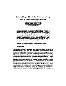
Non structured meshes for Cloth GPU simulation using FEM J. Rodriguez-Navarro1 and A. Susin1 1
Laboratori de Simulació Dinàmica (LABSID), Dept. Matemàtica Aplicada 1, UPC-Barcelona (Spain)
Abstract We present a Finite Element Method (FEM) implementation for cloth simulation on the GPU. The advantages of FEM are twofold: the realism of cloth simulations using this method is improved compared with other methods like the widely used mass-spring one, and it has a wider application rank because it can be used for general triangulated cloth meshes. We are able to detect collisions between cloth and other objects (solids or deformables) and also we deal with self cloth collisions. This is also done in the GPU using image-based collision methods. We have also improved a GPU-Gradient Conjugate method for solving the linear equation systems involved in the FEM solution. Two more methods are also implemented in the GPU to compare with the FEM method: a mass-spring model (based on rectangular meshes) and a constraint method (based on triangular meshes).
1. Introduction Cloth simulation can be considered as a particular case included at the more general framework of deformable models. A deformable model simulation requires the update of the model vertex positions at each time step according to some deformation law. This can be considered like a new object representation at each time step and was not possible take advantage of the old graphic cards for deformable simulations. Nowadays graphic cards incorporate programable capacity for their GPU (Graphics Processor Unity) and allows to read vertex positions from a texture in a vertex or shader program.
have decided to choose the Finite Element Method (FEM) as dynamical model using triangular elements in order to apply FEM to unstructured meshes, which gives us more flexibility when modelling a garment. Moreover, Finite Element methods are obtained directly from elasticity theory which means that material parameters are naturally included in the method.
On the other hand, to achieve a realistic cloth simulation, one has to choose a dynamic model in order to obtain a good approximation of the actual cloth behavior. One of the most used models in the computer graphics community is the mass-spring model [Pro95]. Nevertheless this model has two main drawbacks, first it is designed for structured (or rectangular) meshes. It gives poor results when applied to general unstructured (or triangular) meshes. And second, it is difficult to simulate an actual cloth material because the elasticity parameters included in the model have no relation with the physical parameters used in the industry.
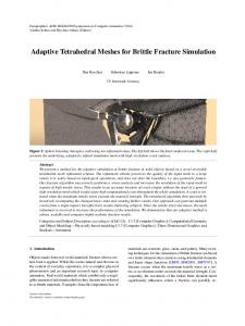
Figure 1: Garment simulation in the GPU for a moving humanoid.
We are interested in dealing with these two drawbacks and also to implement the simulation in the GPU. This way we
When the implementation is aimed to the GPU, structured
c The Eurographics Association 2006.
J. Rodriguez-Navarro & A. Susin / GPU Cloth simulation
meshes are easier to include in the GPU internal texture codification. If unstructured meshes are used, it can be still done but it will require an extra texture to deal with the vertex connectivity. We have implemented the FEM method in the GPU and compare its performance with the implementation, also in the GPU, of the mass-spring model and with the first GPU implementation of the Baraff and Witkin cloth constrain model [BW98] using implicit integration. This model has been considered because, like FEM, it is also defined for unstructured meshes. The paper is organized as follows, section 2 is devoted to previous work in the area, section 3 describes the cloth simulation model and its GPU implementation. Results and conclusions are shown on last section. 2. Previous work on cloth simulation Cloth simulation is a well known and widely studied computer graphics problem. We can roughly classify previous work according to the emphasis on modelling, simulation and computational efficiency. A good reference survey for the field is [NG96]. Early works are essentially devoted to the modelling aspects. Papers by Terzopoulos et al. [TPB87], [TF88] where the first physically-based ones. They introduce cloth simulation for graphics community as a problem of deformable surfaces and used techniques from mechanical engineering like the finite element method and energy minimisation. Other approaches on the dynamic modelling have been, the particle-based models from the works of Breen et al. [BHW94] and Eberhardt et al. [EWS96], the energy-based models from Carignan et al. [CYT92] and Baraff and Witkin [BW98]. The most successful approach in modelling has been the mass-spring one, introduced by Provot [Pro95]. One of the first, present and more successful work in cloth simulation is devoted to the MiraLab team leaded by N. Magnenat-Thalmann. Their contributions start in the early 80’s and have reached many important results in all the above areas classification [Miralab]. Like in other graphics topics, the efficiency of an implementation is related both with the chosen model and the hardware performance. Moreover, a trade-off between speed and precision has to be assumed, the work of Hauth and Etzmuss [HE01], and the one of Volino and MagnenatThalmann [VMT01] discuss the convenience of numerical integrators. The final decision for choosing one simulation model or another is mainly related with the final application field, for video-games or films the requirements are totally different. The work of Jacobsen [Jac01] for the game industry has been the pioneer in introducing a dynamic model for the cloth together with the numerical integrator, the Verlet method, which is suitable for GPU implementations. The first GPU cloth implementation is due to S. Green [Gr03], a structured rectangular mesh cloth and a solid sphere are
simulated using Verlet method on the GPU. Only stretch forces has been simulated. For dealing with collisions on the GPU image based methods are introduced by Vassilev et al. [VSC01] for walking humanoids without dealing with occlusions. Other recent papers by Kolb et al. [KJ01], [KLR04] studies collisions with complex but static objects. Müller et al. [MDM02] presented a FEM-based approach for real-time deformations on the CPU. By estimating the rotational part of the deformation and using linear elasticity, they create plausible animations free of the disturbing artifacts present in linear models and faster than non-linear models. Teschner et al. [THM04] perform deformations on low resolution tetrahedral meshes, coupled with high resolution surface meshes used to visualize the deformed body. FEM methods applied to cloths use typically non-linear elements, because textiles are very flexible and bend easily, forcing deformation being modelled by the Green’s strain tensor. Eztmuss [EKS03] introduce a FEM linear method that can be applied for large deformations using rotation correction directly deduced from the non-linear Green’s tensor. We use ideas from this last paper to implement the FEM method in the GPU and we compare it with our own GPU implementations of the other approaches: the mass-spring model [Gr03] using Verlet integrator, but taken into account also shear and bending forces; and the Baraff-Witkin [BW98] constrain model using implicit integration. 3. Model Description In this section we will describe the method we have used for modelling cloth behavior according to elasticity laws. The dynamics of the cloth will be determined by the Lagrange equation assuming that forces are non-conservative, [GOL50]
M x¨ +Cx˙ +
∂V (x) = fext ∂x
(1)
where x is the position, V (x) is the elastic potential, M is the mass density, C is the damping density and fext are the applied external forces.
x˙ = v
(2)
M v˙ = −Cv − K(x − x0 ) + fext .
(3)
Here K denotes the stiffness matrix computed from the elastic potential as it will be explained next. The deformations produced in the cloth can be expressed in terms of the metric tensor. For in-plane deformations:
εi j =
1 2
�
∂ui ∂u j + ∂x j ∂xi
� (4)
c The Eurographics Association 2006.
J. Rodriguez-Navarro & A. Susin / GPU Cloth simulation
where ui , u j are displacements in the cloth and εi j denotes the deformation terms. If i = j deformation represents the elongation of the cloth, whereas i 6= j is related to shear deformation. Deformations out-plane are obtained using bending forces. The FEM allows to find the solution of a differential equations system representing a model of a physical problem in a continuous medium [ZT93]. Linear elasticity uses a linear strain formulation, the Cauchy strain tensor, as well as a linear material law and yields linear partial differential equations that can be handled efficiently by an implicit time integrator. The reason why linear elasticity is not adequate to simulate cloth behavior is that a linear strain approach is only valid for small displacements or rotations. However, since textiles are very flexible and bend easily, the linear formulation, based on the Cauchy strain tensor is not valid. 3.1. The shape functions FEM methodology is based on considering the continuous material problem as a discrete problem which is solved on a set of points (nodes) associated to the elements that decomposed the geometry domain. The solution is extended to the whole domain by interpolation using the shape polynomial functions Ni associated to each node. Now we present a different way, from the one usually found in many books, to compute the shape functions which is more suitable for GPU implementations. In the linear interpolation case, elements are triangles and nodes are the vertex. Shape functions are linear functions defined implicitly as 1 1 1 1 x x1 x2 x3 N1 (5) y = y1 y2 y3 N2 , N3 z1 z2 z3 z where (xi , yi , zi ), i = 1, 2, 3 are the vertex coordinates. One important property of the shape functions is the normalization condition, included in the first equation of (5) is written as N1 + N2 + N3 = 1. This can be used in order to remove one of the shape functions in the above expression yielding � x − x3 x1 − x3 x2 − x3 � y − y3 = y1 − y3 y2 − y3 N1 , N2 z − z3 z1 − z3 z2 − z3 that can be expressed using the notation ei = (xi − x3 , yi − y3 , zi − z3 )T , i = 1, 2 as � � x − x3 � � N1 y − y3 = e1 e2 N2 z − z3
(6)
Multiplying by the transposed matrix [et1 et2 ] one can obtain c The Eurographics Association 2006.
the explicit expressions for the shape functions and their derivatives: N1 = [(et2 · e2 )(et1 · X) − (et1 · e2 )(et2 · X)]/det N2 = [(et1 · e1 )(et2 · X) − (et1 · e2 )(et1 · X)]/det N3 = 1 − N1 − N2 dN1 = [(et2 · e2 )e1 − (et1 · e2 )e2 ]/det dN2 = [(et1 · e1 )e2 − (et1 · e2 )e1 ]/det dN3 = −dN1 − dN2 where X = (x − x3 , y − y2 , z − z3 )t and det = (et1 · e1 )(et2 · e2 ) − (et1 · e2 )2 . As we pointed out in the previous subsection for large deformations, Cauchy’s strain tensor is not valid and usually Green’s stain tensor G is used. G is expressed in terms of the ∂D ∂D deformation gradient J = ( ∂u , ∂u ): 1
2
1 G = (Jt J − Id). 2 The linearization of Green’s tensor, with the assumption that ∂D the deformation derivatives ∂u are small, yields to Cauchy’s i strain tensor. For each triangle T we compute the shape functions N j and their derivatives rest state.
∂N j ∂ui
associated to each vertex j in the
3.2. Corotational Method As mentioned above, large rotations prevent the use of the linear strain formulation. This is due to that Cauchy’s tensor is not invariant under rotations. Hence, in each time step we are going to remove these rotations before computing the deformation forces. This is known as corotational method and it is equivalent to build a rotated rest state and linearizing with respect to this rest state. For that we consider the polar decomposition of the deformation gradient , that is, the deformation gradient J can be decomposed into a rotation R and a pure deformation U. J = R ·U
(7)
For tetrahedra elements Müller et al. [MDM02] uses a per vertex stiffness warping approach to compute the rotational part. Etmuss et al. [EKS03] introduces another CPU algorithm for triangles based on a SVD decomposition to find the involved rotation. We have implemented a triangle version for the GPU consisting of a new adaptation of the method introduced on [MDM02], [NPF05]. Instead of making a vertex based calculation, we compute a stiffness warping based on the triangle face. If we denote by e1 and e2 two adjacent edges of a triangle in its rest position, we obtain an orthonormal base of the space from a Gram-Schmidt step e˜2 = e2 − (e1 · e2 ) · e1 and finally using the cross product e3 = e1 × e˜2 . This way we
J. Rodriguez-Navarro & A. Susin / GPU Cloth simulation
obtain a base N = [e1 , e˜2 , e3 ] of the space. Analogously, if N˜ denotes the corresponding base associated to the deformed triangle, then the rotational part R is computed as R = N · N˜
xi+1
(8) if
Finally we follow [EKS03] to compute the terms associated to stretch and shear forces. Here the elasticity parameters are introduced according to the type of simulated material.
rit · ri pti · u = xi + α pi
α =
ri+1 t (|ri+1 · ri+1 |
= ri − α u
(12)
< tolerance ) break;
β =
t ri+1 · ri+1 rit · ri
(13)
pi+1 = ri+1 − β pi 3.3. Bend Forces For simulating real cloth a bending term has to be introduced. Most bend forces in textile animation rely on some Laplacian formulation as all models based on springs lead to such a formulation [EG02]. This includes the notable work of Choi et al. [CK02]. Here, we also follow [EKS03] for compute a bending force term.
If we substitute (12) in (13), then GC has the following form p0 = r0 = b − Ax
(14)
for each step u = Api
(15)
t dr = rit · ri+1 , dg = pti · u, db = rit · u, da = ut · u (16)
4. Integration method For the sake of stability, to solve the dynamic system (2) we use an implicit method. We consider the system x˙i+1 = xi + hvi+1
(9)
M v˙i+1 = Mvi + h( fext −Cvi+1 − K(xi+1 − x0 )) (10) Substituting (9) in (10) we get a linear system of equations (M + hC + h2 K)vi+1 = Mvi + h( fext − K(xi − x0 ))
(11)
Denoting A = M + hC + h2 K and b = Mvi + h( fext − K(xi − x0 )) (11) is reduced to the usual form Ax = b. 4.1. Conjugate Gradient on the GPU The above linear system can be solved using different methods. Due to our restriction to the GPU, we have chosen an iterative method well suited for GPU implementation. Although there exists previous GPU implementations of the Conjugate Gradient method [KW03],[GPU-2], we present here an optimal implementation for present graphic cards. The traditional gradient conjugate algorithm using orthogonal directions consists in the following steps:
α=
dr − 2αdb + α2 da dr ,β = dg dr xi+1 = xi + α pi
(17)
ri+1 = ri − α u
(18)
pi+1 = ri+1 + β pi
(19)
if (|βdr | < tolerance) break; This new formulation of the GC method allows to a better data compactification and gives a better performance when using the GPU. We use only two framebuffer objects, in short FBO. One of them attaches the textures of unknown x, residual term r and previous unknown values p. This FBO is used to render the fragment shader which compute the equation (14) and the fragment shader which compute simultaneously equations (17), (18) and (19). We would like to point out that the output of the fragment shader is two colors (p0 and r0 ) in the first case, and three colors (x, r and p) in the second case. To do this we employ the Multi Render Target extension. Furthermore, the draw buffer and read buffer are the same texture saving in this way GPU memory and swap time between textures. The second FBO is used to solve the equation (15) and parallel reduction (16), see [GPU-2] for the details. 4.2. Collision Detection
p0 = r0 = b − Ax for each step u = Api
A lot of effort has been done in this field, however in most cases the collision detection is not carried out integrally on the GPU. Algorithms are divided in two groups: Collisions ( cloth/object ) and Self-collisions (cloth/cloth). For the first case, we use the technique introduced in c The Eurographics Association 2006.
J. Rodriguez-Navarro & A. Susin / GPU Cloth simulation
[RSS05] inspired on [VSC01]. This method is an image based technic, consisting in grabbing the object depth-buffer in each time step such that object deformations, like a human body in our case, are also taken into account. Moreover, the collision detection is made between corresponding pieces of the object and the cloth in a fragment shader. When, based in the corresponding depth, a collision is reported, the involved cloth vertex is marked as a collision vertex for response. One of the key points for having a robust collision detection is related with the number and position of the local cameras chosen to grab the associated depth buffer object.
When implemented on the GPU this correction term introduces only an extra texture.
Figure 3: Collision and Self-collision response example.
5. Results
Figure 2: Local camera position for collision detection. To handle self-collisions we decide to implement on GPU an optimal spatial hashing method [THM03] with the difference that we make a local voxelization for each time step only in the space covered by the cloth. The corresponding hash function for each point X = (x, y, z) is defined as �� � � y − my x − mx z − mz hash(X) = + GS + GS. Mx − mx My − my Mz − mz
We have made a performance test between the three methods discussed in this paper: Mass-Spring, Constraint method and FME. We use a simple cloth model consisting in a rectangular geometry hanging for two points (see fig. 4). The results are shown in table 1 frame rates are obtained using a PC with an AMD 3Ghz and 7800 Nvidia GTX graphic card. As one can see, our FME implementation is still real time for the biggest test mesh. It obtains similar time performance for 64 × 64 mesh but with much more realisme due to the dynamic model.
where m = (mx , my , mz ) and M = (Mx , My , Mz ) are the minimum and maximum respectively of the cloth in each time instant, and GS is the fixed grid size. 4.3. Collision Response In order to achieve a stable collision response, we have adapted a solution introduced in [BW98]. This solution modify both velocity and position using an arbitrary correction term, y, introduced only to move a particle to a desired location during the backward Euler step such that small jumps are filtered. This correction term modifies expression (2) to the following one
x˙ = v + y M v˙ = −Cv − K(x + y − x0 ) + fext . c The Eurographics Association 2006.
Figure 4: FEM simulation corresponding to the test model used for the three methods.
In figure 5 we show an exemple of a more complex cloth scene simulated with FEM on the GPU. Both, collisions and
J. Rodriguez-Navarro & A. Susin / GPU Cloth simulation
Thalmann, D. Dressing animated synthetic actors with complex deformable clothes. Computer Graphics Proceedings, Annual Conference Series, 92: 99–104, (1992).
Table 1: Frame rates obtained with the three methods with CPU and GPU implemetations CPU (GPU)
Mass-Spring
Constraints
FEM
32×32
333 (724)
11 (80)
72 (648)
64×64
22 (181)
1.7 (14.4)
19 (171)
128×128
8 (60)
0.3 (2.6)
[CK02]
K.-J. Choi and H.-S. Ko. Stable but Responsive Cloth. In Siggraph, pages 604-611. ACM Press, July 21-25 2002.
3 (27)
[CST02]
Cordier F., Seo H., and Magnenat-Thalmann N., Made-to-Measure Technologies for an Online Clothing Store. IEEE Computer graphics and applications, 38–48, January 2002.
self-collisions with the woman body and the cloth respectively are detected and treated according to the method explained in the previous sections.
[EWS96]
Eberhardt B., Weber A. and Strasser W. A fast, flexible, particle-system model for cloth draping. IEEE Computer Graphics and Applications, 16: 52–59, 1996.
[EG02]
Etzmuss O. and Gross. J., Deriving a particle system from continuum mechanics for the animation of deformable objects. IEEE Trans. Vis. and Computer Graphics, 2002.
[EKS03]
Etzmus O., Keckeisen M., Straser W., A Fast Finite Element Solution for Cloth Modelling. Proc. Pacific Conference on Computer Graphics and Applications-03, 244–251, 2003.
[GPU-2]
Lefohn A., Kniss J. and Owens J. Implementing Efficient Parrallel Data Structures on GPUs. In GPU gems 2: Programming Techniques for High-Performance Graphics and General-Purposes Computation. Edited by Matt Pharr, pp. 512–545. Addison Wesley, 2005.
[GOL50]
Goldstein H., Clasical Mechanics. AddinsonWesley, 1950.
[Gr03]
Green S., Nvidia developers 2003 http://developer.nvidia.com/object/democloth-simulation.html
[HE01]
Hauth M. and Etzmuss O. A high performance solver for the animation of deformable objects using advanced numericla methods. Computer Graphics Forum. Vol. 20 num. 3, 1–10, 2001.
[Jac01]
Jacobsen T., Advanced Character Physics. Proc. Game Developers Conference’01, 1–10, 2001
[KJ01]
Kolb A., John L., Volumetric model repair for virtual reality applications. In Eurographics short presentations 2001, Univ. of Manchester, 249–256, 2001.
[KLR04]
Kolb A., Latta L. and Rezk-Salama C., Hardware-based simulation and collision detection for large particle systems. In proc. Graphics Hardware’04, T. Akenine-Moller, ¨ M. McCool Ed., 1–9, 2004.
6. Conclusions We have presented an optimal implementation of the FME method for cloth simulation on the GPU. The realism achieved by this approach is ensured by the model because it is based on engineering parameters. The fact that the method is appropriate for unstructured meshes gives more versatility for modelling garments or other cloth pieces. Our complete simulation runs on the GPU, this include the solver for differential equations, the linear system solver and collisions and self-collisions. We have implemented also in the GPU two more methods in order to compare efficiency and visual results.
7. Acknowledgments This research is partially supported by the TIN2004-08065C02-01 CYCIT, and FISs 03/0102 grants. The authors want to thank Dr. Bernhard Spanlang for several interesting discussions about this topic.
References [Bar96]
Baraff D., Linear-Time Dynamics Using Lagrange Multipliers. Computer Graphics Proceedings, Annual Conference Series, 96: 137–146, 1996.
[BW98]
Baraff, D. and Witkin, A. (1998). Large steps in cloth simulation. Computer Graphics Proceedings, Annual Conference Series, 98: 3–54, 1998.
[BHW94]
Breen, D., House, D. and Wozny, M. . Predicting the drape of woven cloth using interacting particles. Computer Graphics Proceedings, Annual Conference Series, 94: 365–372, 1994.
[CYT92]
Carignan, M., Yang, Y., Thalmann, N. M., and
c The Eurographics Association 2006.
J. Rodriguez-Navarro & A. Susin / GPU Cloth simulation
[KW03]
J. Krüger, R. Westermann. Linear Algebra Operators for GPU Implementation of Numerical Algorithms. ACM Transactions on Graphics (Proceedings of SIGGRAPH 2003).
[Miralab]
MiraLab, http://miralabwww.unige.ch/.
[MDM02]
M. Müller, J. Dorsey, L. McMillan, R. Jagnow, B. Cutler, Stable real-time deformations, Proc. of the 2002 ACM SIGGRAPH/Eurographics symposium on Computer animation, 49–54, 2002.
[NG96]
Ng H.N., Grimsdale R.L., Computer graphics techniques for modeling cloth. IEEE Computer Graphics and Applications 16: 28–41, 1996.
[NPF05]
Nesme, M., Payan Y. and Faure, F., Efficient, Physically Plausible Finite Elements. In Proc. Eurographics (short papers), J. Dingliana and F. Ganovelli ed, 2005.
[PFT86]
Press W.H., Flannery B.P., Teukolsky S.A., and Vetterling W.T. Numerical Recipes. Cambridge University Press, 1986.
[Pro95]
Provot, X. Deformation constraints in a massspring model to describe rigid cloth behaviour. In Proceedings of Graphics Interface 95, 141– 155, 1995.
[RSS05]
Rodríguez J., Sainz M., and Susin A., GPU Based Cloth Simulation with Moving Humanoids, Proc. Eurographics Spanish Chapter CEIG-05, J. Regincós, D. Martín. edit., 147155, 2005.
[THM03]
M. Teschner and B. Heidelberger and M. Mueller and D. Pomeranets and M. Gross, Optimized spatial hashing for collision detection of deformable objects. Proc. Vision Modeling, Visualitation, 47–54, 2003.
[THM04]
Teschner M., Heidelberger B., Müller M., Gross M. A versatile and robust model for geometrically complex deformable solids, Proc. of the Computer Graphics International (CGI’04), 312–319, 2004.
[TPB87]
Terzopoulos D., Platt J.C. and Barr A.H. Elastically deformable models. Computer Graphics (Proc. SIGGRAPH), 21: 205–214, 1987.
[TF88]
Terzopoulos and K. Fleischer. Deformable models. Visual Computer, 4:306–331, 1988.
[VSC01]
Vassilev, T., Spanlang, B., Chrysanthou, Y. Fast Cloth Animation on Walking Avatars. Computer Graphics Forum, vol 20 num. 3, 1– 8, 2001.
[VMT01]
Volino P., Magnenat-Thalmann N. Comparing Efficiency of Integration Methods for
c The Eurographics Association 2006.
Cloth Animation", Proceedings of Computer Graphics International (CGI), IEEE Press, pp. 265–274, Hong-Kong, July, 2001 Topic: Virtual Clothing Authors: P.Volino, N.MagnenatThalmann [WBK01]
Witkin A., Baraff D. and Kass M., Physicallybased Modeling. SIGGRAPH Course notes. 2001.
[ZT93]
Zienkiewicz O. and Taylor R., The Finite Element Method, 4th ed. McGraw-Hill, 1993.
Figure 5: Three frames of our FEM cloth simulation on the GPU corresponding to a moving woman wearing a night dress.