Jul 21, 1997 - Timothy J. Burns. Mathematics and Computational Sciences Division, Information Technology Laboratory, National Institute of Standards.
VOLUME 79, NUMBER 3
PHYSICAL REVIEW LETTERS
21 JULY 1997
Nonlinear Dynamics Model for Chip Segmentation in Machining Timothy J. Burns Mathematics and Computational Sciences Division, Information Technology Laboratory, National Institute of Standards and Technology, Gaithersburg, Maryland 20899
Matthew A. Davies Automated Production Technology Division, Manufacturing Engineering Laboratory, National Institute of Standards and Technology, Gaithersburg, Maryland 20899 (Received 31 January 1997) We have developed a new model for chip formation in machining which includes a mechanism for thermomechanical feedback. This leads to an interpretation of metal cutting as a process which is similar in many ways to an open chemical reactor. As the cutting speed is increased, there is a Hopf bifurcation, which explains the observed change from continuous to segmented chip formation. [S0031-9007(97)03568-0] PACS numbers: 62.20.Fe, 81.20.Wk, 82.40.Bj
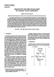
High-speed machining encompasses a number of rapidly developing manufacturing processes. Because these are nonlinear and dynamic in nature, optimization by any means other than trial and error (not uncommon in industry today) requires a fundamental understanding of their physics and new models to predict behavior. Here, we consider single-point orthogonal machining, in which the tool has a plane face and a single straight cutting edge normal to its direction of motion, and the depth of cut d is small in comparison to the length of the cutting edge. Observations in many laboratories over the past fifty years or so have led to the following conventional model of the mechanics of this process [1,2]. As indicated in Fig. 1, the metal cutting occurs by concentrated shear along a distinct narrow region which is approximately planar, called the primary shear zone; this extends from the cutting edge to the work surface ahead of the tool and is inclined at an angle f. The material is unstressed and does not deform until it enters the shear plane. As it approaches this thin layer of thickness h at cutting speed y, the stress in the material builds up rapidly. The shear strain is initially elastic, but the yield stress is exceeded quickly, and plastic flow sets in. Large permanent deformation takes place within the shear zone, and thus a chip separates from the workpiece and moves up the tool face. Although additional plastic deformation, called secondary shear, takes place as the metal moves up the face of the tool, it is treated as a simple friction process in the conventional model, with a chip of thickness b dy sin f assumed to move up the tool face like a friction slider with constant coefficient. (Some more recent models include a secondary shear zone [3].) The model just described is based upon the assumption that the chip forms by a process of steady homogeneous shear, and such a chip is called continuous. In many metals, however, increases in the cutting speed, and hence also in the strain rate, result in the formation of a discontinuous, or segmented, chip characterized by bands of highly local-
ized shear which are almost equally spaced; see Fig. 2(a). Following the onset of segmentation, the spacing between the segments increases monotonically with cutting speed, and approaches some limiting value [4], as indicated in Fig. 2(b). Understanding the onset of this behavior is of practical importance, because discontinuous chip formation is correlated with increased tool wear, decreased tool life, degradation of the workpiece surface finish, and less accuracy in the machined part [5]; for all these reasons, discontinuous chip formation may limit the rate at which metal can be machined [6]. The data for hardened steel in Fig. 2 suggest that a bifurcation from steady state to oscillatory behavior takes place as the cutting speed increases. However, there is no mechanism for oscillations to occur in either the conventional model described above, or in more recent models of segmented chip formation. In what follows, we present a theory which supports the hypothesis that the change from continuous to segmented chip formation is due to a Hopf bifurcation. We propose to modify the conventional model for orthogonal cutting by introducing the concept of a local deformation zone in the workpiece material, based on the observation that the tool distributes a load in the workpiece a certain distance back from the primary shear zone. As we will show, this leads to an interpretation of metal cutting as a thermomechanical feedback process, which is similar in many ways to an open chemical reactor. Recent work by Molinari and Dudzinski [7] is related to our approach; however, they do not consider the connection between local stresses induced on the workpiece material by the tool and the global shear stress in the primary shear zone, and they treat the deformation inside the shear zone as adiabatic. Also, Marusich and Ortiz [8] have recently reported the results of some large-scale Lagrangian finiteelement simulations of orthogonal cutting; just as with a laboratory experiment, we view our simpler modeling approach as an attempt to gain insight into the results of such studies. 447
VOLUME 79, NUMBER 3
PHYSICAL REVIEW LETTERS
21 JULY 1997
compression. Thus, there is an elastic stress S which is proportional to the compressive strain ´, S E´, where ´ sDudysdy sin fd and E is an elastic modulus, which will be discussed further below. Differentiating with respect to time, we get the following evolution equation for S, dS E sin f dsDud E sin f sytool 2 ychip d , (1) dt d dt d where, in the assumed geometry, ytool y cos f. Now, the local compressive stress S causes a shear stress t to build up in the primary shear zone, as follows. Ignoring small inertial terms, balance of momentum requires that SLw twdy sin f. Assuming that L is constant, time differentiation of this equation leads to an evolution equation for the shear stress, L sin f dS EL sin2 f dt sy cos f 2 ychip d . dt d dt d2 (2) FIG. 1.
Primary shear zone model of chip segmentation.
As indicated in Fig. 3, we assume the tool is in contact with the workpiece material over an area A Lw, where w is the width of contact and L is the contact length. Experimental observations indicate that L is of the same order of magnitude as the depth of cut d [2,3], so we make this assumption, also. In order to highlight the essential physical argument, we simplify the geometry by assuming that f a, and we neglect friction as the chip slides up the tool face. Thus, we assume the tool exerts a force on the chip over the contact area A in the direction perpendicular to the face of the tool, which causes the chip to deform. In the present development, we treat this deformation process as a local
FIG. 2. (a) Polished and etched chip cross section obtained from cutting hardened steel at speeds ranging from 0.7 to 4.3 mys, with a 210±, and d 30 mm. (b) Mean segment spacing vs cutting speed.
448
Initially, this shear stress will cause the material in the primary shear zone to deform elastically, so that ychip 0, but eventually t will exceed the yield stress ty of the material, and plastic flow will take place inside the primary shear zone in order to dissipate the excess shear energy. This will take place rapidly at high cutting speeds y. With the onset of irreversible plastic deformation inside the primary shear zone, ychip will become positive, and there will be a plastic strain rate gÙ p in the primary shear zone given by gÙ p ychip yh. Thus, we may rewrite Eq. (2) in the following form: dtydt EL sin2 fsy cos f 2 gÙ p hdyd 2 ELy sin2 f cos fs1 2 gÙ p ygÙ avg dyd 2 ,
(3)
where the average strain rate inside the primary shear zone is defined by gÙ avg y cos fyh.
FIG. 3.
Local deformation zone.
VOLUME 79, NUMBER 3
PHYSICAL REVIEW LETTERS
Confining our attention to the primary shear zone, we assume the following heat balance equation for the temperature: dT T0 2 T T0 2 T 1 t gÙ p . rcg rcg 1 4x dt hysy sin fd h2 (4) Here, T is absolute temperature inside the zone, T0 denotes the absolute temperature of the material entering the shear zone, r is the (assumed constant) density of the workpiece material, cg is its specific heat capacity at constant elastic configuration [9], and x is its thermal conductivity. Equation (4) states that the rate of change of thermal energy in the shear zone is governed by convection, i.e., net inflow divided by residence time in the zone; diffusion, which is approximated by a secondorder difference over the shear zone, assuming that the cut chip material exiting the shear zone is at the same temperature as at the zone center; and heat production by plastic working, assuming for simplicity that all of this work is dissipated as heat [9,10]. Nondimensionalizing temperature by Tˆ sT 2 T0 dyT0 , shear stress by tˆ tyty , length by yˆ yyd, and time by tˆ fsELy sin2 f cos fdysty d 2 dgt, then dropping the hats, the equations governing evolution of shear stress and energy balance in the primary shear zone can be written in the form dtydt 1 2 F, dT ydt 2jT 1 htF , (5) p where F gÙ ygÙ avg denotes the dimensionless plastic strain rate, and £ ° ¢§ j 2ty d 2 1 1 4xy rcg hy sin f ysELh sin 2fd , (6) h ty2 d 2 ysrcg T0 hLE sin2 fd .
(7)
We note that, as the cutting speed increases, the heat transfer parameter j decreases, while the heat production parameter h remains constant. What is still required is a constitutive equation which specifies the irreversible plastic flow response of the material. Since plastic flow at high strain rate is thermally activated, it can be modeled by Arrhenius kinetics [11]. In nondimensional variables, a typical phenomenological Arrhenius model for metals is given by [11–14] Fst, Td exphft 2 s1 2 nT dgyfes1 1 T dgj .
(8)
Here, e is the strain-rate sensitivity of the material, and n is the thermal-softening parameter; e ø 1 and n is of the order of magnitude of 1. When t is less than the temperature-modified yield value Y 1 2 nT , F ø 1, so that essentially no plastic flow takes place. However, as t approaches Y, F becomes significant. (As in the conventional model of machining, strain hardening is neglected here; this important effect increases the dimension of the phase space of our model, and thus may account for more complex aperiodic chip segment spacing
21 JULY 1997
which has been observed at intermediate speeds in some metals [4].) When Eq. (8) is inserted into the model evolution equations (5), the resulting system closely resembles models of open chemical reactors [15]. In particular, the second equation is similar to the balance of energy equation for a chemical combustion process with large activation energy e 21 . The equilibrium state of the system is given by s tstd, T stddd st p , T p d, where t p jysj 1 nhd,
T p hysj 1 nhd .
(9)
This describes steady-state chip formation. Loss of stability of this equilibrium state is thus an indication of the onset of the formation of segmented chips. As pointed out by Recht [16], if the rate of plastic strain becomes sufficiently large, and the transport of heat away from the shear zone is sufficiently slow, the deforming material can become hot enough that its flow stress will drop catastrophically, and the strain will become highly localized into an adiabatic shear band. Shaw and coworkers [2] and Komanduri et al. [5,6,17] have observed that this is the mechanism which causes segmented chips to form. According to our model, this segmentation is caused by a sudden increase in the the displacement rate ychip of the portion of material containing the local plastic deformation zone, as a shear band forms inside the primary shear zone. While this segmentation occurs, the local compressive stress unloads elastically, first inside the shear zone and then further up the tool face, which in turn causes the global shear stress t to decrease. Thus, plastic flow ceases inside the primary shear zone, so that heat production also ceases, but cooling still takes place by convection and conduction. Soon, however, enough new material passes through the primary shear zone for another buildup in stress and temperature to occur. As we will now show, this provides the feedback in stress and temperature which leads to oscillations in these fields inside the shear zone. By linearizing the model equations (5) about the equilibrium state (9) and computing the eigenvalues of the resulting system, it can be shown that the real parts of the eigenvalues equal zero along the neutral stability curve h fsj; e, nd sj 1 j 2 edyfnsj 2 1d 2 ejsn 1 1dg , (10) and ≠fy≠e . 0 for n . 0, ≠fy≠n , 0 for j . 1ys1 2 ed. To proceed further, values of the constitutive parameters e and n are required. Unfortunately, one of the biggest difficulties in modeling plastic deformation at high strain rate is the lack of constitutive data for most materials. It is our hope that the present approach to modeling will lead eventually to improved estimates of constitutive parameters for materials of interest in machining. Here, we choose parameter values which have been determined from torsion tests at a strain rate of 1600 s21 on HY-100 steel, e 0.02 and n 0.73 [14]. 449
VOLUME 79, NUMBER 3
PHYSICAL REVIEW LETTERS
These parameter values lead to the Hopf bifurcation curve in Fig. 4. Thus, points sj, hd below this curve correspond to solutions of (5) which asymptotically approach the steady state (9), while points above this curve correspond to solutions of (5) which asymptotically approach a limit cycle. We estimate the other coefficients (6) and (7) in the nondimensional model equations (5) as follows. We have already assumed that dyL ø 1. Furthermore, for hardened steel, r ø 8000 kgym3 , cg ø 500 Jyskg Kd, x ø 50 WysmKd, ty ø 1.5 GPa. Which elastic modulus to use for E is still an open problem; Young’s modulus is approximately 200 GPa, while the shear modulus is approximately 80 GPa. Thus, ty yE ø 1022 . From Fig. 2(a) we estimate that hyd ø 1021 . Thus, for T0 ø 300 K, we estimate that ty ysrcg T0 d and h are of the order of magnitude of 1, as is the leading coefficient in the definition of j. We also estimate that 4xysrcg d ø 5 3 1025 in the second term in the sum which defines j. For h ø 3 mm, y ø 1 mys, and f ø py6, we thus estimate that j is of the order of magnitude of 10. For fixed h, as j decreases with increasing cutting speed y, Fig. 4 indicates that a Hopf bifurcation can realistically be expected for hardened steel. For copper, on the other hand, if we make the reasonable assumption that the parameter e is still 0.02, and go through the same exercise of estimating j and h, then even if n is larger than 0.72, we find that h is at least an order of magnitude too small for oscillations to occur. These predictions of the model are consistent with what is observed for steel and copper in actual machining operations. Once oscillations occur in the workpiece material, we no longer expect the contact length L to remain constant, i.e., we expect that L scales with the cutting speed y. We are currently developing a reaction-diffusion model, based on the ideas outlined here, to study this.
FIG. 4. (a) Bifurcation curve (10) with e 0.02 and n 0.73. (b) Shear stress t (upper curve) and temperature T (lower curve) vs time t from simulations of Eqs. (5) with zero as initial data and e 0.02, n 0.73, h 2.0 (left to right) j 30— steady state, j 15 — small amplitude oscillations, j 10— relaxation oscillations.
450
21 JULY 1997
In conclusion, we have developed a new lumpedparameter model for orthogonal cutting of metals. The key idea has been the introduction of the concept of a local deformation zone. We have shown that the model explains the observed formation of segmented chips at higher cutting speeds in hardened steel as a supercritical Hopf bifurcation, and it also explains why segmentation is rarely observed during the machining of copper. It is a pleasure to acknowledge helpful conversations with Chris Evans, Tim Whalen, and Tim Wright.
[1] H. Ernst and M. E. Merchant, Trans. ASM 29, 299 (1941); M. E. Merchant, J. Appl. Phys. 16, 267 (1945); 16, 318 (1945); V. Piispanen, Teknillinen Aiakakauslenti 27, 315 (1937); J. Appl. Phys. 19, 876 (1948); E. H. Lee and B. W. Shaffer, Trans. ASME, J. Appl. Mech. 73, 405 (1951); B. F. von Turkovich, Trans. ASME, J. Eng. Ind. 92, 151 (1970). [2] M. C. Shaw, Metal Cutting Principles (Oxford, Oxford, 1984). [3] E. M. Trent, Metal Cutting (Butterworth-Heinemann, Oxford, 1991), 3rd ed. [4] M. A. Davies, Y. Chou, and C. J. Evans, Ann. CIRP 45, 77 (1996). [5] R. Komanduri, T. Schroeder, J. Hazra, B. F. von Turkovich, and D. G. Flom, Trans. ASME, J. Eng. Ind. 104, 121 (1982). [6] R. Komanduri and R. H. Brown, Trans. ASME, J. Eng. Ind. 103, 33 (1981). [7] A. Molinari and D. Dudzinski, C. R. Acad. Sci. Paris Ser. II 315, 399 (1992). [8] T. D. Marusich and M. Ortiz, Int. J. Numer. Methods Eng. 38, 3675 (1995); in Proceedings of the 2nd ECCOMASS 96 Conference on Numerical Methods in Engineering, Paris, France, 1996 (Wiley-International Science, New York, to be published). [9] D. C. Wallace, Phys. Rev. B 22, 1477 (1980). [10] G. I. Taylor and H. Quinney, Philos. Trans. R. Soc. London A 230, 323 (1931). [11] U. F. Kocks, A. S. Argon, and M. F. Ashby, Thermodynamics and Kinetics of Slip, edited by B. Chalmers et al., Progress in Materials Science Vol. 19 (Pergamon, Oxford, 1975). [12] Y. Estrin and L. P. Kubin, Scr. Metall. 14, 1359 (1980); L. P. Kubin, Ph. Spiesser, and Y. Estrin, Acta. Metall. 30, 385 (1982). [13] A. M. Eleiche, Exp. Mech. 21, 285 (1981). [14] T. J. Burns, Trans. ASME, J. Appl. Mech. 57, 836 (1990); J. Mech. Phys. Solids 42, 797 (1994). [15] P. Gray and S. K. Scott, Chemical Oscillations and Instabilities (Clarendon Press, Oxford, 1994). [16] R. F. Recht, Trans. ASME, J. Appl. Mech. 31, 189 (1964). [17] R. Komanduri and T. Schroeder, Trans. ASME, J. Eng. Ind. 108, 93 (1986); R. Komanduri, T. Schroeder, J. Hazra, B. F. von Turkovich, and D. G. Flom, ibid. 104, 121 (1982); R. Komanduri and B. F. von Turkovich, Wear 69, 179 (1981).