an imbalance between the torque transmitted during the positive and negative part of the ... u Ï are assumed vibrate with frequency Ï , and phase difference Ï. ),. (sin. =)( ),(sin. =)( 0 ..... specifies the initial rotor angular velocity and. ) (sgn fsign.
Nonlinear dynamics of a bouncing disk on the tip of a vibrating pretwisted beam Kuang-Chen Liu, James Friend, and Leslie Yeo Department of Mechanical Engineering, Monash University, Clayton, VIC, 3800, Australia Abstract: Stator-rotor interaction is one of the least understood part of piezoelectric ultrasonic motors. In one particular motor design, the rotor is pressed into contact with a pretwisted beam stator that vibrates both axially and torsionally at an ultrasonic frequency. The stator's axial vibration modulates the oscillating frictional torque at the stator-rotor interface so that a non-zero net torque is applied to the rotor. Past analysis of the rotor either neglected the axial motion or assumed it to be fixed in space, with the interaction modelled as a periodic spring contact. In this paper, the rotor is viewed as repeatedly separating and colliding with the stator, a situation analogous to the classic problem of bouncing ball on a vibration platform, except that in this case, the platform also has torsional oscillation. A model assuming Coloumb friction, coefficient of restitution, impulsive friction, and uniform contact pressure is used to investigate the dynamics of the rotor. Keywords: bouncing ball, nonlinear dynamics, piezoelectric ultrasonic motor, stator-rotor interaction.
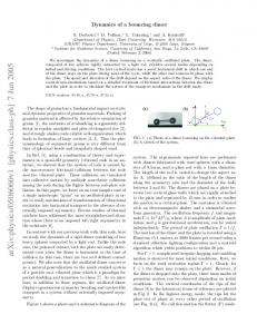
1 Introduction Wajchmann et. al [1] demonstrated a piezoelectric ultrasonic motor composed of a steel ball rotor balanced on the tip of a pretwisted beam that is adhesively bonded to a multilayer piezoelectric actuator (MLPA) (see Figure 1). The motor's operation can be roughly divided into two parts: first, electrical forcing on the MLPA induces a mechanical excitation that results in a combined axial and torsional vibration in the pretwisted beam, second, the frictional torque developed at the stator-rotor interface due to the torsional motion of the stator is modulated by its axial vibration in such a way that there is an imbalance between the torque transmitted during the positive and negative part of the stator's torsional oscillation. The result is a net torque on the rotor in one direction, causing a continuous rotation. The stator-rotor interface of piezoelectric motors presents a big challenge for the design of the motors. There are seemingly two conflicting goals, one is to improve the torque transfer, and other is to reduce wear. Various methods are used to address the above problems, such as the application of preloads by springs, the use of lubrication, and frictional linings. The problem involves a complicated mix of contact and impact mechanics. Past researchers [2, 3] modelled the interaction using equivalent circuit models. In order to take into account the fact that contacts can only support compressive forces, they simply `clipped' the sinusoidal forcing when it fell below zero, with the assumption that the force resumes action immediately when it rise back to zero. This however neglects important features of the rotor's axial motion. A slightly more accurate picture is that the rotor continually separates and collide with the stator, giving rise to frictional impulse and other nonlinear phenomena.
Figure 1. Pretwisted beam piezoelectric ultrasonic motor by Wajchmann et al. [1]
In this paper, a model that accounts for the impulsive nature of the stator-rotor interaction is proposed. The equations governing the motion of the rotor are derived. Due to the discontinuous nature of the bouncing disk's dynamics, the equations has to be solved iteratively; thus, results from computer simulations are presented.
2 Models and assumption 2.1 Impact and contact models The following assumptions are used to simplify the problem. Firstly, the stator undergoes simple harmonic vibration and is unaffected by collisions with the rotor; its axial and torsional displacement at the contact surface (us ,φ s ) are assumed vibrate with frequency ω , and phase difference ψ
us (t ) = U 0 sin (ω t ), where (U 0 , Φ 0 ) respectively.
φ s (t ) = Φ 0 sin (ωt +ψ ),
(1)
are the axial and torsional vibratio n amplitudes
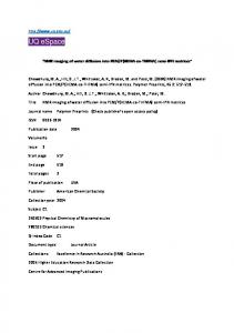
Secondly, torque is transmitted to the rotor by Coloumb friction with coefficient µ , and the contact surfaces on both the stator and the rotor sides are assumed to be rigid flat plates with uniform contact pressure N/A , where N is the contact load and A is the contact area. The torque τ for a circular contact area is the effective frictional torque radius for a circular contact area.
Figure 2. The stator-rotor interface. The rotor is simplified as a bouncing disk.
dN N r 2π N 2rc 2 rdA = − µ ∫ c ∫ r 2 drdθ = − µ πrc = −µreff N , A dA A r =0 θ =0 A 3 where reff = 2rc /3 is the effective frictional torque radius for a circular contact area. τ = − ∫∫ µ
(2)
And finally, coefficient of restitution is used to model the collision between the stator and the rotor
u&s+ − u&r+ = −e(u& s− − u&r− ).
(3)
where the u& s denote axial velocities, the subscripts ( s , r ) denote whether the u& is that of the stator or the rotor, and the superscripts ( + , − ) denote whether the u& is before or after the collision. Since + − the stator motion is assumed to be unaffected by the collision, us = u& s , and the axial velocity of the rotor after impact is
u&r+ = u&s− + e (u&s− − u&r− ).
(4)
2.2 Equations of motion Following the above assumptions, the equations of motion for the axial and torsional motion of the rotor may be derived as
mr u&&r
∞
= − mr g + N + ∑Fˆnδ (t − tn ), n =1
J rφ&&r
∞
= − µreff Nsgn (φ&r − φ&s ) + ∑ − Hˆ n sgn (φ&r− − φ&s− )δ (t − t n ), n =1
(5)
where Fˆn is the axial impulse on the rotor from its n th collision with the stator, δ is the Dirac delta function, t n is the time at which the n th collision occurs, J r is the rotor's moment of inertia, and Hˆ n is the frictional/torsional impulse on the rotor.
&&s ≤ − g , the rotor and the stator Since N is a contact force, it can only be positive, that is, when u separate. Thus N takes the following functional form 0 , u&&s N = mr ( g + u&&s ) , u&&s
≤ −g
or
u s ≠ us
>g
and
ur = us
The axial impulse of the n th collision Fˆn is defined as
(6)
Fˆn
=
∫
tn+
− tn
F (t )dt = mr (u&r+ − u&r− ),
(7)
which upon the substitution of (4)) becomes
Fˆn
= m r (u& r+ − u& r− ) = m r (1 + e)( u& s− − u& r− ). (8) To treat the frictional impulse Hˆ n properly, we need to distinguish between the `available' impulse Hˆ n ,a and the maximum `possible' impulse Hˆ n , p . The `available' impulse Hˆ n ,a is the torsional impulse that is transmitted if friction were present over the whole collision; this is calculated as
t+ = ∫ −n µreff F (t )dA = µreff Fˆn ,
Hˆ n ,a
tn
(9) where the integral is accounted for by noting (7). The existence of a maximum possible frictional impulse stems from the fact that frictional force vanishes when the relative velocity reaches zero (relative acceleration is ignored since the duration of contact in the collision is assumed to be very short). If Hˆ n , p is not considered, scenarios where the relative rotation of the rotor reverses after impact would occur. The maximum possible frictional impulse is thus the impulse that would cause the + + relative angular velocity of the rotor and stator to be reduced to zero. Equating φ&r and φ&s , we can solve the following impulse relations for Hˆ n , p :
Hˆ φ&r+ = φ&s+ = φ&r− − n , p sgn (φ&r− − φ&s− ), Jr + Eliminati ng φ& gives us
and
Hˆ φ&s+ = φ&s− + n , p sgn (φ&r− − φ&s− ). Js
(10)
s
Hˆ n , p
=
J s J r &− &− φr − φs . Js + J r
(11)
The frictional angular impulse thus takes t he following form
Hˆ Hˆ n = n ,a Hˆ n , p
, if , if
Hˆ n ,a ≤ Hˆ n , p . Hˆ n , p < Hˆ n ,a
(12)
2.3 Nondimensionalization At least 5 variables and 9 parameters are used to describe the stator-rotor interaction, for example (ur , u s , φr , φs , t ) and (reff , mr , J r , e, µ , g , ω , U 0 , Φ 0 ) ; the problem is thus nondimensionalized to reduce the number of parameters. Here, the nondimensional form of the variables are denoted with an s while the characteristic length scales are denoted with a c ;
ur , s
=
ur , us ,s ur , c
=
us u s, c
φr , s
=
φr , φ s, s φr ,c
=
φs , ts φs ,c
=
t . tc
(13) The characteristic scales of the stator variables were chosen to match the vibration amplitude, us ,c = U 0 , φs ,c = Φ 0 . The other three characteristic scales were then chosen to si mplify the equations of motion as much as possible. If we choose the following scales
tc
=
U0 , g
u r ,c = u s, c = U 0 ,
φr,c =
reff µm r U 0 = Rφ Φ 0 , Jr
(14)
where Rd is a forcing amplitude ratio and Rφ is an angular amplitude ratio;
Rd
r Φ = eff 0 , U0
2 r g
Jr = m r ,
r µm r reff reff Rφ = eff = r J r Rd g
2
µ , R d
(15)
the equations of motion are nondimensionalized as follows
u&&r , s
∞
= −1 + N s + ∑Fˆn ,sδ s (t s − t n , s ), n =1
φ&&r , s
∞
= − N ssgn ( Rφφ&r ,s − φ&s, s ) + ∑ − Hˆ n , s sgn (Rφφ&r ,s − φ&s, s )δ s (t s − t n , s ), n =1
(16)
where N s , Fˆn ,s and Hˆ n , s are the nondimensionalized contact load, linear impulse and frictional angular impulse:
0 Ns = 1 + u&&s ,s
, u&&s ,s , u&&s ,s
≤ −1
or
u r , s ≠ u s ,s
>1
and
u r , s = u s ,s
Fˆn , s = (1 + e)(u& s, s − u& r , s ), Hˆ n ,a , s = Fˆn , s , and
Hˆ Hˆ n ,s = n ,a , s Hˆ n , p , s
,
(17)
, ifHˆ n ,a , s , ifHˆ n , p , s
≤ Hˆ n , p ,s , < Hˆ n , a ,s
(18)
1 Hˆ n , p , s = Rφ φ&r−,s − φ&s−,s . Rφ
(19)
2.4 Separation and collision When the magnitude of the stator's axial acceleration is less than the gravitational acceleration holding the stator and the rotor together, the rotor remains in contact with the stator, and torque is transmitted by either sliding or static friction. During sliding contact the frictional torque is τ f = reff µ k N , while
&&s |= ω U 0 ≥ g or during static contact it is τ f = J r φ&&s . If the axial forcing is large enough ( | u 2
| u&&s ,s |= ω 2U 0 /g = ω 2 t c2 = ω s2 ≥ 1 ), the rotor separates from the stator; axially, it follows a parabolic trajectory, while the angular speed remains constant. If the rotor becomes airborne after collision n at time t a , height u a , and axial velocity u& a , then its time at the next collision t n +1 is determined by the first solution of the following transcendental equation
g (t − tn )2 + u&a (t − tn ) + ua . 2 Its landing speed u& L and landing height ua would be U 0 sin (ωt ) = −
u&L
= − g∆tn + u&a ∆t n ,
uL = U 0 sin (ωt n +1 ) = −
(20)
∆t n2 + u&a ∆t n + ua , 2
(21)
where ∆t n = t n +1 − t n and t n +1 is the first solution to (20) .
2.5 Torsional sliding modes For `dull' impacts (e.g. if e = 0 ), the rotor remains in contact with the stator immediately after
&&s |≤ ω U 0 . During this time the frictional collisions and before the separation occurs at t sep where | u 2
forcing on the rotor may be one of three cases depending on the relative stator -rotor angular velocity ( φ&rel = Rφ φ&r ,s − φ&s, s ), and the absolute stator angular acceleration φ&&s , s : 1. `static' if φ&rel = 0 and | φ&&s ,s |< available friction 2. `slide +' if φ&rel > 0 , or φ&rel = 0 but φ&&s ,s < – available friction 3. `slide –' if φ&rel < 0 , or φ&rel = 0 but φ&&s ,s > available friction
For `static' contacts, φ&rel remains zero, i.e. φ&r , s = φ&s , s . For `slide ± ' contacts, however, we need to solve (16). The impulsive terms can be neglected, and the axial forcing is non-zero, hence the equation to solve is
φ&&r , s = −(1 + u&&s , s )sgn (Rφφ&r ,s − φ&s, s ),
(22)
which has the following solution,
φ&r , s = −fsign [( t − t0 ) + (u&s , s (t ) − u& s, s (t 0 ))] + φ&0 ,
(23)
where ( t 0 , φ&0 ) specifies the initial rotor angular velocity and fsign ≡ sgn ( Rφ φ&r ,s − φ&s ,s ) co rresponds to the sign of φ&rel . During contact, the rotor may either be slipping or rotating at the same angular velocity as the stator. If it is slipping, frictional forces accelerate the rotor until the relative velocity is zero, thereafter, depending on the stator acceleration and the friction threshold, the rotor may change slip direction or rotate with the stator at the same speed. If the rotor rotates with stator, it will start slipping again when the stator's torsional acceleration exceeds the frictional threshold. The time tslip when this occurs is &&s ,s ). found by solving for the first root of | φ&&s ,s |= Rφ (1 + u The rotor continues to slip and stick until the rotor loses contact with the stator.
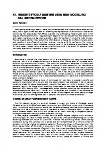
3 Simulation results To solve (16) for the rotor's angular velocity φ&r ,s and axial displacement ur ,s , a knowledge of the − collision times t n and collision velocities u& r , s (t n ) are needed. However, to determine the n th collision condition, one must have the information about the ( n − 1) th collision. The problem is thus iterative, where each iteration begins and ends with a stator-rotor collision. Each iteration is divided into different stages that can be treated analytically, such as collision, torsional sliding, and parabolic flight. For a fully defined set of nondimensional equations of motion, the following input parameters need to be chosen: e -- coefficient of restitution, Rφ -- angular amplitude ratio, ω s -- nondimensio nalized stator vibration frequency, ψ -- phase difference between axial and torsional stator vibration. Figures 3 and 4 shows the bouncing disk's flight paths and angular velocity with the following parameters: ω s = 1.5, Rφ = 0.01, ψ = 0 . The change of the coefficient of resitution from 0.3 to 0.6 shows a change from a regular 2 period trajectory to what appears to be irregular, chaotic behaviour. Figure 5 shows a comparison of the simulations result for e = 0.6 after 300 collisions with experimental measurement of the velocity-time curve of a prototype motor. The bouncing disk model appears to be able to capture some of the behaviour of the actual motor: a first order system response with a high frequency oscillation about the general trend. Note however that the parameters usedin the simulation are chosen arbitrarily and they do not necessarily correspond to the actual motor. Further work on a systematic study of the parameters in the bouncing disk model is needed.
Figure 3. Trajectory of the bouncing ball: e = 0.3, ω s = 1.5, Rφ = 0.01, ψ = 0
Figure 4. Trajectory of the bouncing ball: e = 0.6, ω s = 1.5, Rφ = 0.01, ψ = 0
Figure 5. A comparison of the measured angular velocity of a prototype motor with a bouncing disk simulation.
4 Conclusion A new model for the stator-rotor interaction is proposed that takes the repeated separation and collision of the stator and rotor into account. The governing equations for the model are derived and nondimensionalized, giving rise to a nonlinear problem with four parameters: coefficient of resitution, forcing frequency, phase difference between the axial and torsional forcing, and a angular amplitude ratio. Preliminary results show that the model has the potential to capture the high frequency oscillation of the motor's angular velocity.
5 References [1]
David Wajchmann, Kuang-Chen Liu, James R. Friend, and Leslie Yeo. An ultrasonic piezoelectric motor utilising a non-circular cross sec tioned twisted beam. IEEE Transactions on Ultrasonics, Ferroelectrics, and Frequency Control, (under peer review).
[2]
Kentaro Nakamura, Minoru Kurosawa, Hisayuki Kurebayashi, and Sadayuki Ueha. An estimation of load characteristics of an ultrsonic motor by measuring transient responses. IEEE Transactions on Ultrasonics, Ferroelectrics and Frequency Control, 38:481–485, 1991.
[3]
Kentaro Nakamura, Minoru Kursawa, and Sadayuki Ueha. Design of a hybrid transducer type ultrasonic motor. IEEE Transactions on Ultrasonics, Ferroelectrics and Frequency Control, 40(4):395–401, July 1993.