Nonlinear Integral Backstepping Control for Induction Motor drive with Adaptive Speed Observer using Super Twisting Strategy (Full text in English)
Mohamed HORCH1, Abdelmadjid BOUMEDIENE2, Lotfi BAGHLI1,2 1
Université de Tlemcen, LAT, Algeria; 2Université de Lorraine, GREEN, EA 4366, Vandoeuvre-lès-Nancy, France
Abstract This paper presents a nonlinear Integral backstepping control approach applied to an induction motor fed by a power voltage source without speed sensor. We present the implementation of the integral backstepping control for induction motor drives based on the field oriented control technique. We also present the mechanism of adaptive super twisting speed and rotor flux observers with the only assumption that from stator voltages and currents are measurable. The objective is to improve the speed control, the rotor flux control under load torque disturbances and parameter variations. The overall stability is demonstrated using Lyapunov theory. Simulation results prove clearly high robustness against disturbances; the estimated flux and rotor speed converge to their actual values. Keywords: field oriented control, induction motor drive, integral backstepping, lyapunov function, sensorless drive, super twisting Received: September, 08, 2015
1. Introduction The induction motor (IM) plays an important role in industrial applications, due to simplicity of design and maintenance, robustness and low cost [1]. The model of IM is nonlinear, multivariable and greatly coupled have a fairly complex control. The progress in nonlinear control and the considerable technological advances, both in the field of power electronics and in microelectronics, made possible the implementation of high performance control of induction motor, making it a must in the areas of variable speed and fast torque control. This motor is a serious candidate for nonlinear control [2]. In this paper, we use a backstepping technique to synthesize a sensorless vector control of induction motor. The backstepping technique is a systematic and recursive method of synthesis of nonlinear control law based on Lyapunov functions that ensure the stabilization of each synthesis step [3]. At each step of the process, a virtual control is generated for ensuring the convergence of the system to its steady state [4]. This technique allows the synthesis of control laws taking into account disturbances or parameters mismatch [5]. The modification of Backstepping control by adding Integral action is an interesting
solution to improve the robustness of backstepping control and to eliminate residual errors [6]. The state variables used in the development of induction motor control (flux, speed ...) are often difficult to obtain for technical or economic reasons (difficulty or impossibility of measuring, fragility, size, cost and maintenance). Dedicated sensors represent the weak link in the chain, so we try to fulfil their role by estimation using electrical variables. Therefore, the mechanical speed sensor is completely replaced by software which are based on calculation algorithms [7]. During last years, various sensorless control schemes have been presented and are now used in many fields of electric drive. Estimators and observers can be classified into the following categories: Estimators in open loop, estimators based on harmonic analysis, MRAS techniques, nonlinear and adaptive observers. Estimators are sensitive to parameters variations. Using observers improves the robustness of the estimation in regard of parametric variations and measurement noises [8]. The proposed technique is based on the approach developed by H. Kubota and al [9] which uses an adaptive observer to estimate the motor speed. The contribution of this work is based on the replacement of the adaptive
ELECTROTEHNICĂ, ELECTRONICĂ, AUTOMATICĂ, 64 (2016), nr. 1
mechanism from a conventional PI controller, to a super-twisting adaptive control algorithm. The aim is to boost the accuracy of the estimated speed and decrease the influence of the parameter uncertainties.
2.1. Model of IM in (d-q) Reference Frame The mathematical model of the three-phase induction motor can be expressed in the (d-q) synchronous rotating frame by the following nonlinear equations [10] [11]:
di sd = a1 .i sd + ω s .i sq + a 2 .φ rd dt − a 3 ω r .φ rq + b.V sd dt
= a1 .i sq − ω s .i sd + a 3 .φ rd .ω r + a 2 .φ rq + b.V sq
the following condition [12] [13]: φr = φrd = L m ⋅ isd and φrq = 0
(2)
3. Integral Backstepping control 3.1. Application principle
2. Mathematical Model of Induction Motor and Vector control
di sq
25
(1)
dφ rd = a 4 .i sd − a 5 .φ rd + (ω s − ω r ).φ rq dt dφ rq = a 4 .i sq − a 5 .φ rq − (ω s − ω r ).φ rd dt dω r = a 6 .(i sq .φ rd − i sd .φ rq ) − a 7 .ω r − a 8 .Tl dt with: 2 L L .R a1 = −b. R s + m .Rr , a2 = m r L (σ.Ls.L2r) r
Lm L .R R p2.Lm , a4 = m r , a5 = r , a6 = (σ.Ls.Lr ) Lr Lr J.Lr L2 f p 1 a7 = c , a8 = , σ = 1 − m , b = Ls.Lr J J σ . Ls
a3 = −
2.2. Direct field Oriented Control for Induction Motor The field oriented control strategy is very efficient to get high-performances for induction motor drive in terms of torque and speed. The principle of this technique is to make the behaviour of the induction motor similar to that of a DC motor, for which a natural decoupling exists between the control of the torque and the magnetic flux. This is done by correctly computing the dq reference frame to cancel the quadrature component of the flux. We must find the right Park’s angle so that the rotor flux vector is entirely on the daxis, the decoupling is obtained by imposing
The basic idea of backstepping control is to make closed loop systems equivalent to firstorder subsystems in cascade that are Lyapunov stable. This gives ensures robustness and asymptotic global stability. Our aim to control the flux and speed variables. To let them follow particular trajectories, we chose as intermediate variables, the stator currents. They must follow their reference values defined by the “virtual control”. Finally, we compute the voltage controls (stator voltages) required to let the “virtual controls” converge to the desired values with regards to the stability of the associated Lyapunov function [14] [15] [16]. 3.2. Application of conventional backstepping control to induction motor In our work, we provide Integral backstepping control by using the model of the leakage oriented induction machine equation (1) [17]. Our objective is to synthesize the expression of the control variables Vsd and Vsq to let the state variables of the induction motor follow the desired references. By making a variables change, the new ones are the errors between the set points and the state variables. This control is presented in four steps [6], as we will show in this section. The motor has to reach the desired speed under a rated magnetic flux φrd . We must first compute speed and rotor flux errors. a) First step “speed loop” For the electrical speed ωr , we define the tracking error as: e 1 = ωr* − ωr
(3)
And their dynamics are given by: & r∗ − ω &r e& 1 = ω
(4)
Then the error dynamical equations are:
e&1 = ω*r − a 6 iqs ϕ rd + a 7 ω m + a8Tl The first Lyapunov function is chosen such that:
ELECTROTEHNICĂ, ELECTRONICĂ, AUTOMATICĂ, 64 (2016), nr. 1
26 v 1 (e 1 ) = 1 e 12 2
(5)
Its derivative is:
(
& r* − a 6 .i sq .φrd + a 7 .ωr + a 8 .Tl v& 1(e1 ) = e1 ω
)
(6)
(
) (7)
with k 1 is a positive constant. The derivative of the Lyapunov function becomes:
Since the current i sq is not a control input and is only one variable of the system with its own dynamics. We will use it to introduce the integral action, so we choose the desired dynamic behaviour of the virtual control i *sq as following:
(
1 k 1e1 + ωr* + a 7 .ωr + a 8 .Tl φrd .a 6
+ λ 1χ1
)
v& 2 (e 2 ) = e 2 .e& 2
(12)
1 v& 2 (e 2 ) = −e 2 . &i *qs − δ1 − Vsq σL s
For a negative error derivative e 2 , we must choose v sq = σL s k 2 e 2 + &i *sq − δ1 as the first
)
(
control voltage.
with k 2 is a positive constant. c) Third step “flux loop” We define the tracking error as: * −φ e 3 = φ rd rd
(13)
* − φ& e& 3 = φ& rd rd
(8)
λ 1 is positive constant and t χ1 = ∫0 e1(τ )dτ is the integral action brought in
accordance with the following error " e" . By introducing this integral in the virtual control, we ensure the convergence of the tracking error to zero in steady state.
(14)
* + a .φ −a .i e& 3 = φ& rd 5 rd 4 sd
The third Lyapunov function is chosen such that: v 3 (e 3 ) = 1 (e 32 ) 2
(15)
Its derivative is: v& 3 (e 3 ) = e 3 .e& 3
b) Second step “ i sq current loop” For this step, our goal is the replacement of the virtual current control by computing control voltages. We define the error of the q-axis component of the stator current and its reference. (9)
The derivative is written as: e& 2 = &i *sq + λ1.e1 − &i sq
Its derivative is:
And its derivative with respect to time leads to:
With
e 2 = i*sq + λ1.χ1 − isq
(11)
v& 2 (e 2 ) = −k 2 e 22 < 0
v& 1 (e1 ) = −k 1e12 < 0
i *sq =
δ1 = −a1isq − ωs isd − a3φrdωr v 2 (e 2 ) = 1 e 22 2
The objectives of tracking are performed (v& 1(e1 ) < 0) choosing the quadrature current as virtual control which represents the stabilizing function as follows: 1 k1e1 + ωr* + a 7 .ωr + a 8 .Tl φrd .a 6
1 Vsq σL s
with
v& 1 (e1 ) = e 1.e& 1
i *sq =
e& 2 = &i *qs − δ1 −
(16)
(
* + a .φ −a .i v& 3 (e 3 ) = e 3 φ& rd 5 rd 4 sd
The tracking objectives are achieved (v& 3 (e 3 ) < 0) by choosing the reference of the current component as follows: i *sd =
(
1 * +a φ k 3 e 3 + φ& re 5 rd a4
)
with k 3 is constant positive. (10)
)
(17)
ELECTROTEHNICĂ, ELECTRONICĂ, AUTOMATICĂ, 64 (2016), nr. 1
The derivative of the Lyapunov function becomes: v& 3 (e 3 ) = −k 3 e 32 < 0
The desired dynamic behaviour of the virtual control with integral action i *sd is given by:
isd* =
(
)
1 k3e3 + φ& *re + a5 φrd + λ 2 χ 2 a4
(18)
(19)
with k 4 is a positive constant. This leads to stabilize the system by the increased Lyapunov function of energy:
[
1 2 e + e 22 + e 22 + e 22 2 1
]
(22)
(20)
1 e& 4 = &i *sd − δ 2 − Vsd σL s
ˆ φr = φr2α + φr2β
δ 2 = −a1isd + ωs isq + a 2 φrd (21)
v& 4 (e 4 ) = e 4 .e& 4
(24)
For the proposed sensorless vector control, the rotor flux and position are determined by the following relationships: ˆ φrβ ˆ θ s = arctg ˆ φrα
with
(23)
which leads to: − k 1e12 − k 2 e 22 − k 3 e 32 − k 4 e 24 < 0
The derivative of the error variable is:
1 v& 4 (e 2 ) = −e 4 . &i *ds − δ 2 − Vsd L σ s
)
v& 4 (e 4 ) = −k 4 e 24 < 0
V& e = −k 1e12 − k 2 e 22 − k 3 e 32 − k 4 e 24
e 4 = &i *sd + λ 2 .e 3 − &i sd e& 4 = &i *sd − &i sd
(
Its derivative is:
d) Fourth step “isd current loop” e 4 = i *sd + λ 2 .χ 2 − i sd
For the error derivative e 4 to be negative we must choose v sd = σL s k 4 e 4 + &i *sd − δ 2 as the second control voltage.
Ve =
with λ 2 is positive constant, and χ 2 = ∫0t e 3 (τ)dτ
27
(25) (26)
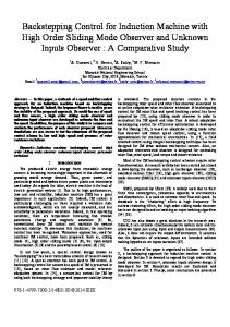
The Integral backstepping control for induction motor with the proposed observer can be presented by the block diagram shown in Figure 1.
Figure 1. Block diagram of backstepping control scheme based induction motor drive
4. Speed and flux estimation by the Adaptive Observer In this section, the conventional adaptive observer is presented. Its goal is the
reconstruction of the rotor flux and speed without a mechanical sensor. The rotational speed of the induction motor is not measured and is considered as an unknown parameter in the observer equation system.
ELECTROTEHNICĂ, ELECTRONICĂ, AUTOMATICĂ, 64 (2016), nr. 1
28
4.1. Model of observer The mathematical model of induction motor, expressed in the (α − β ) stationary reference frame allows having a good compromise between stability and simplicity of observer, can be described by the following state equation [18]:
X& = A ⋅ X + B ⋅ U Y = C ⋅ X
(27)
where
[
X = i s α i sβ φ r α φ r β
[
ddf ddd
U = v s = v sα v sβ
0 a1 0 a4
a 6 0 B= 0 0
0 a 6 0 0
]
[
T
a 3 .ωr a 2 − ωr a5
a2 − a 3 .ωr a5 ωr
1 0 0 0
, C= 0 1 0 0
(
ˆ& = A ˆ⋅X ˆ + B ⋅ U + G ˆis − is X
]
(28)
[
]
g2 g1
)
[
ˆi = ˆisα ˆisβ and s
g3 − g4
ˆ−A ∆A = A
0 0 ˆ−A = ∆A = A 0 0
c ⋅ ∆ωr 0 − ∆ωr 0
0 0 0 − c ⋅ ∆ωr 0 0 0 ∆ωr
g4 g 3
The speed adaptation law is given by:
1 d ˆrβ − e isβ .ˆ . ∆ωr = e isα .φ φrα / c λ dt ω ˆr = ∫
(
)
λ ˆrβ − e isβ .φ ˆrα .dt e isα .φ c
(
(29)
)
(30)
(31)
(33) (34)
with K w = λ.
1− σ σ.L m
This adaptation law has been established for almost constant speed, to improve the dynamic of speed observation, we replaced the pure integral by a PI controller as follows [20]:
( ) +K i ∫ (e isα .ˆ φrβ − e isβ .ˆ φrα ) ⋅ dt
ˆrα ⋅ dt ω φrβ − e isβ .φ ˆ r = K p . e isα .ˆ (35)
with e isα = i sα − ˆisα And e sβ = i sβ − ˆisβ
]
T
Are respectively the vectors of the measured and the estimated stator currents. G is the observer gain matrix which imposes its dynamics. It is calculated as follows [9-19]: g1 G= − g 2
(32)
with
ω φrβ − e isβ .ˆ φrα .dt ˆ r = ∫ K w e isα .ˆ
with i s = i sα i sβ
)
∆ωr = ω ˆ r − ωr : Error on speed.
T
The coefficients a1 , a 2 , a 3 , a 4 , a 5 and a 6 have the same expressions as those defined in equation (1). The state observer, which estimates the stator current and the rotor flux is written as follows [9]:
T
( )(
c = L m / σ ⋅ L s ⋅ Lr
]T
, Y = i s = i sα i sβ The state equations can be rewritten as:
a1 0 A= a 4 0
( )
d d ˆ = (A + G ⋅ C) ⋅ X − X ˆ + A−A ˆX ˆ e = X−X dt dt ˆ = (A + G ⋅ C) ⋅ e − ∆A ⋅ X
(31)
By naming e = X − Xˆ , the dynamics of the estimation error of the adaptive observer is obtained by:
K p And K i are the proportional and integral gains respectively. The matrix of the adjustable gain G of the observer will ensure the stability and the dynamics of desired observation. The coefficient k is chosen so that the observer will responds faster than the system. R 1− σ 1 + c. g1 = (1 − k ). s + σ σ . L . T T s r r
g 2 = (k − 1).ω ˆr
ELECTROTEHNICĂ, ELECTRONICĂ, AUTOMATICĂ, 64 (2016), nr. 1
g3 =
(k
)
L − 1 Rs 1− σ + + c. m . c σ . L σ . T Tr s r
2
(1 − k ) . + c
Rs 1− σ 1 σ.L + σ.T + c. T s r r
29
r
u = −λ p s sgn(s) + v v& = −λ i sgn(s)
(36)
Where u represents the control signal, λ i and λ p are the control gains, s is a sliding
k − 1 g4 = ˆr .ω c The structure of the adaptive observer is shown in Figure 2.
variable, r is a positive constant, 0 < r ≤ 0.5 . The adaptation laws based the super twisting Control Algorithm are obtained for the estimation of speed can be designed as (34). r
ω ˆ r = λp s sgn(s) + v v& = −λi sgn(s)
(37)
where the sliding variable is ˆ ˆ λ s = e isα .φrβ − e isβ .φrα , and gains λ i and p are positive constants. A block diagram of the speed estimation control with super twisting sliding mode is shown in Figure 3.
Figure 2. Block diagram of adaptive observer
5. Adaptive Super-Twisting Observer Design
rotor speed (rad/s)
100
speed reference speed estimated
80 60 40 20 0 0
2
4
6
time (s)
8
10
Error of speed estimation
The enhancement provided in this section consists in the replacement of the conventional PI controller by a super twisting control algorithm. The super twisting sliding mode algorithms are excellent controllers to solve problems of speed estimation and have the ability to compensate the uncertainties of the mathematical model [21] [22]. The super twisting algorithms have been developed in the context of higher order sliding mode control theory. Now, consider the super twisting control algorithm, which is given by [23]:
Figure 3. Block diagram of control loop of speed estimation with STSM regulator
5. Simulation results The results exposed below were obtained by numerical simulations, performed for the nonlinear integral backstepping control without Speed Sensor associated with the adaptive observer applied to the induction motor drive for the values of the following coefficients: K1 = K2 = 500, K3 = K4 = 1800, λi = 10000, λp = 10200, k=0.96. These coefficients are obtained by tryerror procedure. 0.5
0
-0.5 0
2
4
6
time (s)
8
10
ELECTROTEHNICĂ, ELECTRONICĂ, AUTOMATICĂ, 64 (2016), nr. 1
30
0 -10 0
2
4
6
8
10
Stator voltage (V)
Stator current (A)
400
10 200 0 -200 -400 2.5
2.6
2.7
10
5
0 0
2
4
6
8
10
5 0 -5 -10 0
0.5
0 6
8
10
Electromagnetic torque (Nm)
Rotor flux in d-q axis (Wb)
rotor flux-drotor flux-q-
4
3
2
4
6
8
10
8
10
time (s)
1
2
2.9
10
time (s)
0
2.8
time (s) Stator current in q axis (A)
Stator current in d axis (A)
time (s)
20 10 0 -10 -20 0
2
4
time (s)
6 times(s)
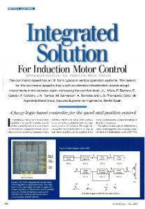
Figure 4. Performance of the proposed observer at high and low speed region with two load variations
These figures describe the high performance of the closed loop system (observer and controller) in terms of trajectory tracking and disturbance rejection. The speed of the machine correctly follows its reference even under conditions where the machine is unobservable (between 7 and 9 sec) [24], The disturbance rejection is very satisfactory as low speed or high speed. Nevertheless, there is a small difference at application times of load torque steps. The results also show a good flux control. 6. Conclusions This paper presents the application of nonlinear integral backstepping technique for sensorless vector control of induction motor. The proposed method is to use an adaptive observer based on a super twisting control strategy for the estimation of the speed and the rotor flux by using Lyapunov theory to show the system stability. The speed and rotor flux are estimated only with sensing electrical variables.
Analysis of the results confirms the superiority of the super twisting approach that allows a sensorless control with a high level of performance not only in terms of precision and robustness of the estimation, but also in terms of reference tracking and disturbance rejection. 7. Nomenclature
Tem, TL : Electromagnetic torque, load torque. isd, isq : Stator currents. φrd,φrq : Rotor flux.
ωm : Electrical angular. σ : Total leakage factor. R s and R r : Stator and rotor resistances. L s and L r : Stator and rotor inductances. L m : Mutual inductance. p : Number of pole pairs. J : Moment of inertia. fc : Friction coefficient.
ELECTROTEHNICĂ, ELECTRONICĂ, AUTOMATICĂ, 64 (2016), nr. 1
8. Appendix Table 1. Nominal parameters of the induction motor used: Rated power Rated voltage Rated speed Nominal frequency Rated stator current Stator resistance Rotor resistance Cyclic stator inductance Cyclic rotor inductance Mutual inductance Number of pole pairs Moment of inertia Friction coefficient
1.5kW 220V 1428rpm 50Hz 3.64 4.85Ω 3.805Ω 0.274H 0.274H 0.258H 2 0.031kg/m2 0.00114Nm.s/rd
9. Acknowledgment This work was financially supported by the Automatic Control Laboratory (LAT) of University Tlemcen (Algeria), the authors wish to thank the head of the laboratory.
10. References [1] Mehazzem F., Nemmour A.L., Reama A., Benalla H., “Nonlinear integral backstepping control for induction motors”, Electrical Machines and Power Electronics and 2011 Electromotion Joint Conference on, vol. 36, no. 3, pp. 331-336, Sept. 2011. [2] Mehazzem F., Reama A., Hamam Y., Benalla H., “Real time implementation of backstepping controller in indirect field oriented control of induction motor drive”, Second International IEEE Conference on Power Engineering, Energy and Electrical Drives, POWERENG, March 2009. [3] Kechich A., Mazari B., “Application to Adaptive Backstepping for Permanent Magnet Synchronous Machine” Electrotehnica, Electronica, Automatica, vol. 60(2012), nr. 1 [4] Boughazi O., Boumedienne A., Aymen O., “An Efficiency Backstepping Control without Speed Sensor applied to the Induction Motor Voltage Supplied” Electrotehnica, Electronica, Automatica, vol. 62(2014),nr. 1 [5] Loucif M., Boumediene A., Mechernene A., “Maximum Power Point Tracking Based on Backstepping Control of Wind Turbine” Electrotehnica, Electronica, Automatica, vol. 62 (2014), nr. 3 [6] Traoré D., De Leon J., Glumineau A., Loron L. “Adaptive Interconnected Observer-Based Backstepping Control Design for Sensorless Induction Motor: Experimental results”. Soumis à Control Engineering Practice 2008. [7] Saheb T. Commande sans capteur mécanique de la machine asynchrone, thèse de doctorat, Université de Nantes, IREENA, Octobre 2004.
31
[8] Mechernene A., Zerikat M., Chekroun S., “Adaptive Speed Observer using Artificial Neural Network for Sensorless Vector Control of Induction Motor Drive”, Automatika, 53(2012) 3, pp 263–271. [9] Kubota H., Matsuse K., Nakano T., “DSP-based speed adaptive flux observer of induction motor”, IEEE Transactions on Industry Applications, vol. 29, no. 2, pp. 344-348,1993. [10] Quang N.P., Dittrich J.-A., Vector control of three-phase AC machines, system development in the practice. Springer Berlin: 2008. [11] Bocker J., Mathapati S., “State of the Art of Induction Motor Control”, in Proceedings book of IEEE International Conference on Electric Machines & Drives, IEMDC ’07, vol. 2, pp. 14591464, 3-5 May 2007. [12] Baghli L., Contribution à la commande de la machine asynchrone: Utilisation de la logique floue, des réseaux de neurones et des algorithmes génétiques, thèse doctorat, Université Henri Poincaré, Nancy-I, 1999. [13] Blaschke F., “The principle of field oriented as applied tothe new transvector closed-loop control system for rotatingfieldmachine,” Siemens Review XXXIX, vol. 5, no. 4, pp.217220, 1972. [14] Boudjema F., Benchaib A. and Rachid A., Backstepping approach for nonlinear ROSlidingmode Control of an induction motor,Mediamira Science Publisher, POBox 1173400 Cluj-Napoca, România, 1998. [15] Lin F.-J., Chang C.-K., and Huang P.-K., “FPGA-Based Adaptive Backstepping SlidingMode Control for Linear Induction Motor Drive,” Power Electronics, IEEE Transactions on, vol. 22, no. 4, pp. 1222–1231, Jul. 2007. [16] Tan H., Chang J., “Field Orientation and Adaptative Backstepping for Motor Control”, Control and Power Technology Rockwell Science Center 1049 Camino Dos Rios Thousand Oaks, CA 91360, IEEE, 1999. [17] Laoufi A., Hazzab A., Bousserhane I.K., Rahli M., "Direct Field-Oriented Control using Backstepping Technique for Induction Motor Speed Control", in International Journal of Applied Engineering Research, ISSN 0973-4562, Vol.1 No.1 (2006) pp. 37-50. [18] Farhani F., Zaafouri A., Chaari A., “Gainscheduled Adaptive Observer for Induction Motors: An LMI Approach” Acta Polytechnica Hungarica, Vol. 11, No. 1, pp.49-61, 2014. [19] Zamora J.L., Garcia-Cerrada A., “Online Estimation of theStator Parameters in an Induction Motor Using only Voltageand Current Measurements”, IEEE Transactions on Industry Applications, vol. 36, no. 3, pp. 805-816, 2000. [20] Wang C., Li Y., “A novel speed sensorless field-oriented control scheme of IM using extended Kalman filter with load torque
32
ELECTROTEHNICĂ, ELECTRONICĂ, AUTOMATICĂ, 64 (2016), nr. 1
observer,” in Proceeding book of the Applied Power Electronics Conference and Exposition, Twenty-Third Annual IEEE, vol. 2008, pp. 17961802, February2008. [21] Lascu C., Blaabjerg F., “Super-twisting sliding mode direct torque contol of induction machine drives,” in Energy Conversion Congress and Exposition (ECCE), 2014 IEEE, 2014, pp. 5116– 5122. [22] Goh K.B., Dunnigan M.W., Williams B.W., “Robust chattering-free (higher order) sliding mode control for a vector-controlled induction machine,” in Control Conference, 2004. 5th Asian, 2004, vol. 2, pp. 1362–1370 Vol.2 [23] Lascu C., Boldea I., Blaabjerg F., “SuperTwisting Sliding Mode Control of Torque and Flux in Permanent Magnet Synchronous Machine Drives” Industrial Electronics Society, IECON 2013-39 th Annual Conference of the IEEE, pp. 3171–3176, 10-13 Nov. 2013. [24] Traore D., Commande non lineaire sans capteur de la machine asynchrone, Thèse en vue de l’obtention du titre de docteur de l’Ecole Centrale de Nantes, France, soutenue publiquement le 19-11-2008.
11. Biography Mohamed HORCH was born in Ain Temouchent, Algeria, on January 22, 1990. he received the M.Sc. in Electrical Engineering from the University of Tlemcen, Algeria in 2013. Currently he is a PHD student at the same university.He is an member of Automatique Laboratory of Tlemcen (LAT). His areas of interest are electrical machines drives, process control, power electronic, estimation and observation techniques to electrical drive systems. Correspondence address: Department of Electrical and Electronics Engineering, LAT, Faculty of Technology, University of Tlemcen, 13000
Tlemcen, Algeria, e-mail:
[email protected]
Abelmadjid BOUMEDIENE was born in Béchar, Alegria, in 1967. He received the Engineer degree in Electrotechnics, the Magister degree and Ph.D degree in electric engineering, from the Ecole Nationale Polytechnique (E.N.P), Algiers, Algeria, in 1991, 1994 and 2007 respectively. Upon graduation, he joined the Electric Engineering Department of University of Bechar. He was an associate Professor, member of Process Control Laboratory (ENP). Since 2012, he joined the Electric Engineering Department of University of Tlemcen. He is Professor and member of Automation Laboratory of Tlemcen (LAT). His research interests include electric machine drives, power electronics and process control. Correspondence address: Department of Electrical and Electronics Engineering, LAT, Faculty of Technology, University of Tlemcen, 13000
Tlemcen, Algeria, e-mail:
[email protected] Lotfi BAGHLI was born in 1971. He received the Diploma degree (with Hons.) in electrical engineering from the Ecole Nationale Polytechnique of Algiers, Algeria, in 1994 and the DEA and PhD degree in electrical engineering from the University Henri Poincaré, Nancy, France, in 1995 and 1999, respectively. He was a Lecturer at Nancy University and a member of Research Group Electrical and Electronics of Nancy. He is currently a Visiting Lecturer at Tlemcen University, Tlemcen, Algeria. His research interests include digital control using DSP, PSO and genetic algorithms applied to the control and identification of electrical machines. Correspondence address: Laboratoire GREEN, Université de Lorraine, F-54500 Vandoeuvre-lèsNancy, France, e-mail:
[email protected]