Nonlinear Predictive Control of Under-actuated Mechanical Systems. Application : the ECP. â. 505 inverted pendulum. Ahmed Chemori Mazen Alamir.
Nonlinear Predictive Control of Under-actuated Mechanical Systems Application : the ECP∗505 inverted pendulum Ahmed Chemori
Mazen Alamir
Laboratoire d’Automatique de Grenoble.UMR 5528, BP46,Domaine Univesitaire, 38400 Saint Martin d’H`eres, France. Ahmed.Chemori(Mazen.Alamir)@inpg.fr
Abstract This paper is devoted to the control of under-actuated mechanical systems. The Lagrange dynamics of such systems are nonlinear, and they have fewer actuators than the degrees of freedom. Another key feature of these systems include nonlinear coupling between the actuated and the unactuated degrees of freedom, non holonomic constraints, and non minimum phase zero dynamic. We discuss a low dimension nonlinear predictive based control approach for stabilization and limit cycle generation. The stability issue is discussed using a graphical tool, it’s the Poincar´e’s section that enables the investigation and analysis of the overall scheme stability. The proposed scheme is tested through simulation on the ECP 505 inverted pendulum. The robustness of the proposed controller is tested in two cases, namely towards parameter uncertainties, and towards external disturbances. Key-words : under-actuated mechanical systems, nonlinear optimization, nonlinear predictive control
1
Introduction
Under-actuated mechanical systems are those systems which have less control inputs than generalized coordinates (degrees of freedom) i.e they have generalized coordinates that are not actuated, and this is a source of dynamic contraints which are generally non integrable and therefore second order non holonomic. Many examples of such systems exist, and mainly in robotics, they include, among others, the under-actuated robot manipulators, the gymnast robots and particularly the acrobot, the pendubot, the planar vertical takeoff and landing aircrafts, the undersea vehicles and other mobile robots. An other basic feature of these class of systems is the nonlinear dynamics that they have, moreover their actuated coordinates are nonlinearly coupled with the unactuated coordinates. ∗ Educational
Control Products
The under-actuation in these mechanical systems is generally introduced by intentional design to reduce the manufacturing cost, the weight, and/or failure rate, so the obtained systems may be able to perform complex tasks with a reduced number of actuators, but they require new approaches to design effective control strategies, therefore they constitute a rich framework of nonlinear control problems of both practical and theoretical interest, and for that they are attracting more and more attention of researchers from nonlinear control community. In the literature many research efforts have been made on control aspects [9, 6, 5, 12, 8, 11, 13] but the field of control of such systems still open to develop other control strategies. In [12] a technique design combining partial feedback linearization and Lyapunov methods based on saturation functions, switching and energy shaping have been proposed. In [13] the author discuss a survey on some existing results such as geometric nonlinear control, passivity based control in the purpose of stabilizing and tracking control. Three control algorithms have been proposed in [5] for an underactuated two link robot, namely an LQ controller, a partial feedback linearizing regulator, and a sliding mode controller. In [6] the testbed is also a two link under-actuated robot but the actuator is located at the base (in contrast to that proposed in [5] where the actuator is located at the joint between the two links) and the authors propose a method based on partial feedback linearization, nilpotent approximation and an iterative stabilization procedure. Roughly speaking they propose an open loop control which is able to steer the system closer to the desired equilibrium point in finite time, and apply it iteratively, which provide a robuste exponential convergence to the equilibrium. In [8] the authors discuss the nonlinear behavior of the same robot proposed in [6] through a graphical tool which is the Poincar´e map. The study in [9] concerns the under-actuated mechanical systems with several actuated degrees of freedom and single unactuated degree of freedom, where the authors propose a discontinuous nonlinear feedback controller enables
the closed loop equilibrium at the origine to be globally attractive. This paper provide a new low dimensional nonlinear predictive control scheme effective for under-actuated mechanical systems even with more than one degree of under-actuation, especially when the problem of computing time could be overcome. As an example of application, the control of the ECP 505 inverted pendulum [2] is considered, on which simulations have been investigated. To state the efficiency of the proposed controller a robustness study is carried out towards parameter uncertainties and towards external disturbances, and experimental scenarios are currently on test. This paper is organized as follows, in next section the dynamic modelling of under-actuated mechanical systems is investigated. The proposed control scheme is illustrated in section 3, where it is detailed as well as its associated stability analysis based on the Poincar´e section. In section 4 the selected under-actuated mechanical system to be used to test our approach is presented, where a description of its testbed is given as well as its dynamic model. The obtained simulation results are given in section 5. The last section is devoted to end the paper with a conclusion.
2
Dynamic modelling of underactuated mechanical systems
Using the Lagrange formulation[14, 10], the nonlinear dynamic model describing a mechanical system with n−degree of freedom could be developed M (q)¨ q + N (q, q) ˙ q˙ + G(q) = S(q)u
(1)
Where q ∈ Rn is the vector of the generalized coordinates, M (q) ∈ Rn×n is a symmetric positive definite inertia matrix, N (q, q) ˙ ∈ Rn×n is a matrix including the Coriolis and centrifugal terms, G(q) ∈ Rn is the vector of the gravitational terms. u ∈ Rm is the input generalized forces, and S(q) ∈ Rn×m is the matrix distributing the control inputs on the generalized coordinates and it has a full rank for all q. Note that the number of the control inputs m is less than the degrees of freedom n, and the mechanical system due to this fact is under-actuated. This assumption suggest that the vector of the generalized coordinates may be partitioned into two parts as follows T T q = [qaT qna ] (2) Where qa ∈ Rm corresponds to the actuated coordinates, qna ∈ Rn−m corresponds to the unactuated coordinates, and S(q) = [Im×m ; 0(n−m)×m ] ∈ Rn×m . Follow this partition the dynamics (1) can be rewritten as follows M11 q¨a + M12 q¨na + N11 q˙a + N12 q˙na + G1 = u M21 q¨a + M22 q¨na + N21 q˙a + N22 q˙na + G2 = 0
(3) (4)
3
The control approach : a nonlinear predictive controller
Partial feedback linearization provide two alternatives, collocated linearization and non collocated linearization [13]. In the former the control linearizes the equations associated with actuated degrees of freedom, whereas in the latter it linearizes those associated to the passive degrees of freedom. The collocated linearization corresponds to an input/output linearization [3] with respect to an output map y = qa . Let the corresponding coordinates transformation and the partially linearizing feedback be µ ¶ ξ x ¯= ; x = Φ(¯ x) ; u = Ψ(x, v) (5) η Which leads to the following system feedback equivalent to the original ξ˙ = Aξ + Bv ; ξ ∈ Rnξ η˙ = Z(ξ, η, v) ; η ∈ Rnη
(6) (7)
The key idea of the control approach is inspired from the control of biped walking robots, and hybrid dynamical systems in general. Let us define the discrete instants (in biped robots it corresponds to the impact instants, and in hybrid dynamical systems it corresponds to the jump instants) denoted by tk = kτc , where k ∈ N+ , and τc > 0 is some fixed period. Let us define some target sub-state ξ f to be reproduced periodically on the actuated degrees of freedom, that is the aim is to use the controlled variables to reach this state periodically at the discrete instants tk , this could be better expressed by ξ(tk ) = ξ f
;
∀k ∈ N+
(8)
Onces the pair (τc , ξ f ) is fixed, an infinite number of trajectories should be able to join the end-points expressed by condition (8). Let us therefore introduce the following definition Definition 1 Let np ∈ N be some integer. For any subset P ⊂ Rnp , we call a P-family of admissible parameterized trajectories a map T : Rnξ × P × [0, τc ] → Rnξ
(9)
such that the following limit conditions are satisfied for all p ∈ P and all ξ 0 ∈ Rnξ 1. T (ξ 0 , p, 0) = ξ0 and T (ξ 0 , p, τc ) = ξ f 2. T (ξ 0 , p, ·) is compatible with the linear system (6). That is, if the system (6) is at the initial condition (0, ξ 0 ), then exact tracking of the trajectory T (ξ 0 , p, ·) is possible under some suitable timevarying feedback defined over [0, τc ] v(τ ) = V(ξ0 ,p) (ξ(τ ), τ )
∀τ ∈ [0, τc ]
(10)
which in a more compact form may be written as ´ ³ ; t ∈ [tk , tk+1 ] (13) η(t) ˙ =: ϕ η(t), η(tk ), p(tk ), ξ f
The closed loop dynamic (11) of η is obtained by integration of (13) between two discrete instants tk , tk+1 . Let us now introduce the following lemma to summarize
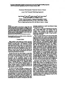
Figure 1: The parameterized family of admissible trajectories
On figure 1 more illustration of the above definition could be obtained. Roughly speaking, a P-family of admissible trajectories provide a finite dimensional parameterization of trajectories joining two points in Rnξ and that can be exactly tracked by the ξ-linear controllable system (6) using the state feedback control (10). The application of such feedback between each two discrete instants tk−1 ,tk enables the tracking of the trajectories, which leads to ξ(tk ) = ξ f , therefore a suitable choice of a tool for the stability analysis leads to the definition of the Poincar´e section at the discrete instants. This tool enables the stability analysis of the whole system, so if under some choices ¡ suitable ¢ it can be proven that the sequence η(tk ) k∈N obeys + an asymptotically stable dynamic law, the stability of the whole system follows. The key feature is that under (10) and for a given fixed value of ξ f , there is some F : Rnη ×P → Rnη such that the dynamic of η is given by ´ ³ (11) η(tk+1 ) = F η(tk ), p(tk ), ξ f where p(tk ) ∈ P is the parameter that select the trajectory1 T (ξ(tk ), p(tk ), ·) to be tracked by the substate ξ over [tk , tk+1 ]. Since the feedback law (10) enables a perfect tracking (regardless theoretically the saturation of the actuators) to be performed over [tk , tk+1 ], the predicted evolution of the sub-state η over this interval is given by (7), namely ³ ´ η(t) ˙ = Z ξ ref (t), η(t), v ref (t) where
ξ
ref
(t)
=
v
ref
(t)
=
³ ´ T ξ(η(tk )), p(tk ), t ¡ ¢ V(ξ(η(tk )),p(tk )) ξ ref (t), t
lemme 1 Assume that a compatible output map h(x) has been defined leading to a partial feedback linearization. Let a pair (τc , ξ f ) ∈ R+ × Rnξ be given. Let (pk )k∈N ∈ P N be a sequence of parameters in P. There is a map F : Rnη × P → Rnη such that under the feedback law given by v(t) = V(ξ(tk ),pk ) (ξ(t), t)
1 within the P-family of admissible trajectories in the sense of definition 1
t ∈]tk , tk+1 ]
(14)
the resulting discrete dynamics of η is given by η(tk+1 ) = F (η(tk ), pk , ξ f )
(15)
The dynamic expressed by (15) represents a discretetime controlled system in which η is the state and p is the control input. Therefore, the choice of the control pk may be made by using classical design methodologies for discrete-time nonlinear systems. However, the implicit nature of the map F (·) makes difficult the use of analytical design method and incites to use predictive control tools [4, 1, 7]. In fact, such control strategies need no analytical manipulations to be performed in order to derive the feedback law. More precisely, the control pk is computed by solving the following optimization problem pk = pˆ(η(tk ), ξ f , η f ) := min kF (η(tk ), p, ξ f ) − η f k2Q (16) p∈P
where ξ f and η f are defined by the desired target xf by the coordinates transformation Φ given by (5), namely µ f¶ ξ := Φ−1 (xf ) (17) ηf Injecting the feedback (16) in (15) the following closedloop dynamic will be deduced η(tk+1 )
= :=
Fcl (η(tk ), xf ) (18) f f f F (η(tk ), pˆ(η(tk ), ξ , η ), ξ )
Which can be expressed in a multi-steps form (k0 steps) by successive compositions as follows η(tk+k0 )
(12)
;
=
Fclk0 (η(tk ), xf )
(19)
It is possible now to express the following stability results: Proposition 1
1. If for some k0 ∈ N, Q > 0 and some ρ > 0, the map Fclk0 satisfies the following inequality ΨQ k0 (r) :=
h
sup kη−η f k2 =r Q
i kFclk0 (η, xf ) − η f k2Q ≤ µ · r (20) ;
µ 0, there is some ρ > 0 and some positive ε < ρ such that the two following inequalities hold i h (r) ≤ε (22) sup ΨQ k0 and ΨQ k0 (r) ≤ µr
;
µ