Microelectronic Engineering 162 (2016) 85–88
Contents lists available at ScienceDirect
Microelectronic Engineering journal homepage: www.elsevier.com/locate/mee
Research paper
Nonvolatile organic resistive switching memory based on poly(o-methoxyaniline) film Tiantian Wei, Gang Chen, Shuai Zhang, Yang Chen, Yuting Hu, Ran Jiang, Yuxiang Li ⁎ School of Physics, Shandong University, Jinan, Shandong 250199, China
a r t i c l e
i n f o
Article history: Received 11 December 2015 Received in revised form 13 May 2016 Accepted 14 May 2016 Available online 16 May 2016 Keywords: Organic Resistive memory Poly(o-methoxyaniline) Electrical properties Conductive filaments
a b s t r a c t Resistive switching memories have attracted considerable attention for their potential applications in next-generation nonvolatile memory devices due to high switching speed, high volume storage, low power consumption, and non-destructive readout. In this paper, a controllable and nonvolatile rewritable bipolar organic memory based on the active poly(o-methoxyaniline) (POMA) film is demonstrated. The capacitive device structure of Al/POMA/ITO exhibits good bistable resistive switching characteristics with a high ON/OFF current ratio of ~103, low switching voltage, good cycling endurance, and long retention time of over 104 s. The observed bipolar switching phenomena could be elucidated by the formation and annihilation of conductive filaments, which corresponded to oxidation and reduction of metal Al top electrode and/or POMA polymer molecule chains. © 2016 Elsevier B.V. All rights reserved.
1. Introduction Resistive random access memories (RRAM) with two terminal cross-bar device structures are one of the most potential alternatives for up-coming nonvolatile memory applications due to their high storage density, low power consumption, good size scalability, simple structure, non-destructive readout, etc. [1–4]. In addition, their exceptional electrical memory performance with high response speed, low operation voltage, and multi-bit storage potential satisfies the requirements well for new emerging memory technologies [5]. One aspect of the electrical bistable resistive memory that has received considerable attention in recent years is organic-based RRAMs due to their material varieties and advantageous properties such as feasible solution-processed fabrication, low cost, large area processing, and flexibility. There are various organic materials that have been found to exhibit resistive switching effect including small organic molecules [6–8], polymers [9–12], π donor– acceptor complexes [13–15], systems containing mobile ions and redox species [16–17], hybrid organic–inorganic systems [18–20], and so on [21–26]. There are also a variety of mechanisms to explain the conductance switching phenomena on the basis of filament formation [1,5], electric field induced charge transfer effect [8,15], charge trapping/ detrapping, the potential barrier changing related tunneling effects [12], etc. To date, the continuous research for a stable and reliable resistive switching behavior has resulted in many findings on various material combinations, device configurations, and operating mechanisms. ⁎ Corresponding author. E-mail address:
[email protected] (Y. Li).
http://dx.doi.org/10.1016/j.mee.2016.05.017 0167-9317/© 2016 Elsevier B.V. All rights reserved.
Conjugated polymer usually possesses the specific physical properties as a semiconducting/conducting material. The π-π interactions between the conjugated groups along polymer molecular chain give the feasible structural control and functionality for the applications on organic electronics. Conjugated polymer poly(o-methoxyaniline) (POMA), a derivative of polyaniline (PANI), contains a methoxy (– OCH3) group in the aromatic ring in the ortho-position to the amino group. The presence of the electron donor –OCH3 substituent increases the processability and solubility of POMA in organic solvents, while maintaining similar optical and electronic properties comparing to PANI [27–29]. With other advantages of low production cost, being environmentally benign, good thermal stability, and robust biocompatibility, POMA has been extensively studied in the applications of electronic, photovoltaic and optic properties [30–34]. However, the studies for POMA (including its composites) focus mainly on the device applications in organic thin film transistors, solar cells, and sensors [35–40]. However, the bistable resistance switching behavior in RRAM memory device with POMA as an active layer has not been explored yet. As known, bistable electrical-switching and the nonvolatile rewritable memory effect have been found in a two-terminal device with PANI or PANI composites as an active layer [17,41]. Having similar structure and electrical property as PANI, PMOA device is expected to exhibit good resistive switching performance. The research for the resistive switching characteristics of POMA-based RRAM devices has a certain significance to broaden the applications of PANI derivatives in organic electronics. In this study, we report the electrically bistable resistive memory device characteristics based on the conjugated polymeric material of
86
T. Wei et al. / Microelectronic Engineering 162 (2016) 85–88
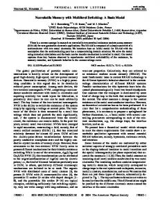
POMA. The memory behavior was measured based on a simple metal– polymer–metal configuration of the spin-coated POMA film sandwiched between an aluminum top electrode and indium-tin oxide (ITO) coated glass. The effect of top electrode area on the electrical switching properties was explored, and the resistive switching mechanism was inferred. These results could provide the new insight for high-performance organic electrical memory applications. 2. Materials and methods POMA used in this study was obtained commercially from Alfa Aesar. A fresh solution of 1 wt.% of POMA dissolved in N,N-dimethyl formamide (DMF) was spin-coated onto ITO glass substrate at 500 rpm for 5 s and 5000 rpm for 60 s with N2 blowing. The N2 blow to the ITO electrode surface can improve the uniformity of POMA layer and accelerate the DMF solvent evaporation during the deposition. Prior to the POMA film deposition, the ITO coated glass was cleaned in acetone, methanol, and finally de-ionized water with ultrasonic cleaning for a duration of 15 min each, and the solution was filtered through a 0.22 μm filter. The spin-coating procedures were repeated four times to yield the desired film thickness of ~ 50 nm. Prior to the next spin-coating deposition, the POMA film was annealed at 100 °C for 10 min in a vacuum of ~ 10−3 Pa. After the final film deposition, POMA was vacuum annealed for 2 h at the above temperature to enhance the film densification and uniformity. For top electrical contact, Al electrodes with a thickness of 200 nm were deposited on the POMA layer by electron-beam evaporation through a shadow mask. Different electrode diameters ranging from 200 μm, 300 μm, 400 μm, and 500 μm were chosen to investigate the dependence of the conductance switching behavior on the cell area. For bottom electrical contact, the edge of the spin-coated POMA film was removed with acetone to expose the underlying ITO substrate. Fig. 1 shows the schematic of the Al/POMA/ITO device and POMA molecular structure. The electrical characterization of the memory device was performed on an Agilent B1500A semiconductor parameter analyzer under ambient conditions. During electrical measurement, the ITO bottom electrode was grounded, and all electrical biasing was applied onto the Al top electrode. The resultant film morphology and thickness were determined using a NanoScope Multimode and NanoScope Dimension 3100 Atomic Force Microscopy (AFM). 3. Results and discussion The Al/POMA/ITO structure devices with 50-nm-thick active layer exhibit very interesting bistable electrical behavior. Fig. 2 shows the typical current density-voltage (J-V) characteristics of a POMA RRAM device with 0.05 V sweeping step. As other RRAM devices, a preelectroforming process was necessary in POMA memory for stable and reproducible switching characteristics. In the forming process, a strong positive bias on the top Al electrode from 0 to 5 V was applied, turning the device into a low resistance state (LRS) and then a sequence electric stimuli 5 V → 0 V → −5 V → 0 V applied to switch the device back to a high resistance state (HRS) again. However, not all POMA RRAMs have an initial HRS, some memories showed an electrically conductive state
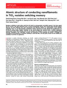
Fig. 2. Typical J-V curves of Al/POMA/ITO device. The inset shows the J-V characteristics in 10 switching cycles.
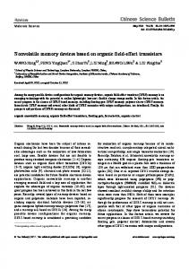
(LRS). In any cases, the electroforming process was necessary for the subsequent stable switching operation. In switching property measurement, a negative voltage was first swept from 0 to −3 V (sweep 1) and then returned to 0 V (sweep 2), followed by a positive-voltage sweep from 0 to 5 V (sweep 3) and returned to 0 V (sweep 4) again. In sweep 1, an abrupt increase in current density occurred at a threshold voltage of −1.15 V (VSET), indicating a device transition (“SET” process) from the HRS (OFF) to LRS (ON). The device remained in the LRS in sweep 2 even removing the power supply. Then, a positively biased sweep 3 is applied and program the LRS back to the initial HRS (“RESET” process) with sufficient magnitude of 2.9 V (VRESET). The HRS of the device can be maintained in sweep 4 and re-programmed to the LRS again in the subsequent negative sweeps. The ratio of current (ION/OFF) in HRS to that in LRS of the device is about 103 at a read voltage of 0.5 V, which is high enough to promise the low misreading rate through precisely controlling the LRS and HRS states. The operation cycles can be repeated with fairly good accuracy (see inset in Fig. 1) despite minor variation in the SET and RESET voltages, indicating that the POMA device exhibited stable bipolar resistive switching characteristics with low switching voltage. In order to investigate the endurance performance of the Al/POMA/ ITO memory, cyclic switching operations were conducted. Fig. 3a and b illustrate the evolution of resistance of the two well-resolved states and the cumulative probability at 0.5 V in 100 cycles, respectively. As shown in Fig. 3a, although the resistance values exhibited some fluctuations in both LRS and HRS, the resistances of HRS and LRS maintained good stability with a ratio of 103 and did not show markedly degradation within 100 switching cycles. Fig. 3c and d report the evolution and statistical distribution of VSET and VRESET in 100 switching cycles. When the cell was repeatedly switched between LRS and HRS, the VRESET changed in a range from 1.85 V to 3.8 V, while the VSET changed between −2.1 V and −0.7 V. Fig. 3e displays the retention performance of the memory cell under ambient conditions. Little degradation of the memory device in both the LRS- and HRS-resistances and relatively narrow distribution in both the SET- and RESET-voltages indicate that the switching between the ON and OFF states of the device is reliable. Both the LRS and
Fig. 1. Schematic of Al/POMA/ITO device and the molecular structure of POMA.
T. Wei et al. / Microelectronic Engineering 162 (2016) 85–88
87
Fig. 3. (a) Evolution and (b) cumulative probability of resistance of Al/POMA/ITO memory in 100 cycles, (c) evolution and (d) statistical distribution of VSET and VRESET in 100 cycles, and (e) retention performance of the device.
HRS can be retained for more than 104 s of the continuous stress test. During the retention test, the memory window of over 103 was achieved and did not show any serious electrical degradation, indicative of the stability of the active material and the electrode-POMA interface. The number of read cycles and retention ability are related to the stability and reliability of the memory device. These measurements ensured that the resistance switching of the device is controllable, reproducible, nonvolatile, and stable. To better understand the conduction and resistive switching mechanism of the memory operation, the previous J-V curves were re-plotted in a double logarithmic scale for the negative voltage sweep. As can be seen in Fig. 4a, an ohmic conduction behavior with linear J-V relationship was observed in the LRS after the SET process, which is an evidence of confined filamentary conduction induced by the formation of a conductive channel between top and bottom electrodes [42]. Two distinct regions, however, are observed during switching the device from HRS to LRS as the negative bias increases from 0 to the threshold voltage VSET. In the low-voltage region (b 0.6 V), the current is directly proportional to the applied bias (J–V) as a result of the thermally generated free carriers, while a square dependence of current density on the applied voltage (J–V2) was observed in the intermediate-voltage region (N0.6 V). At the intermediate bias regime, the current is controlled by the traps in the POMA layer via thermally activated hopping conduction. When the voltage is increased further, almost all the traps in the polymer film are filled with electrons. At this time, the current flows via thermionic emission and a sudden current jump is obtained which set the device switching from HRS to LRS. The indicated numbers in J-V log-log curves denote the slope values of individual region. Similar switching behavior is observed for the positive voltage sweep. This switching characteristics in the HRS is in good agreement with the space charge limited current (SCLC) model, which consists of three different portions: the Ohm's law region (V b 0.6 V), the Child's law region (0.6 V b V b 1.15 V), and the steep current increase region (V N 1.15 V) [43]. The total different conduction behavior in LRS and HRS suggests
that the high conductivity in LRS should be a confined filamentary effect rather than a homogenously distributed one [42]. To further confirm the filamentary conduction behavior, the dependence of the resistance in HRS and LRS (RHRS and RLRS) on cell area were
Fig. 4. (a) Double-log plot analysis of the absolute value of the J-V curves for negative voltage sweeps and (b) cell size dependence of the HRS and LRS resistances.
88
T. Wei et al. / Microelectronic Engineering 162 (2016) 85–88
measured. If the conducting filament is formed in SET operation, the current (or resistance) in LRS should be independent on cell size as the conducting filament is a local phenomenon, while the resistance in HRS usually decreases with increasing the cell size. The results displayed in Fig. 4b show that the RHRS reduced by one order of magnitude and the RLRS remained stable at about 40 Ω when the diameter of top electrode increases from 200 μm to 500 μm. RHRS exhibits a clear dependence on the cell size, indicating that current flow was through the whole cell area in the HRS. The independence of RLRS on the cell area indicates that the conductive filaments are formed in the LRS, which are localized and sufficient to bypass the current [23,44]. About the formation of conducting filament, two types of filamentary conduction, a metal Al filament and a POMA+ carbon filament, are possibly proposed for the POMA-based RRAM devices. Since our devices use Al as top electrode, the redox of metal Al and diffusion into the POMA film could be one of possible reasons for the conducting filament formation. As the introduction above, an initial electroforming procedure is invoked to our POMA memories for the subsequent stable operation. Simultaneously, the SET and RESET process to turn the device ON and OFF are dependent on the bias polarity. A sufficient positive voltage can trigger the POMA RRAM a conductive state, whereas a negative bias cannot do. The dependence of the memory switching property on the bias polarity and a pre-electroforming process indicate that the electrode material may govern the device switching operation [45]. During the electroforming process, a high positive voltage of 5 V was applied to ionize the top Al electrode, which could be described as Al → Al3+ + 3e−, and the electrical field would drive aluminum ions into polymer layer. Subsequently, when a negative voltage was applied, the reduction of aluminum ions by the injected electrons and accumulation of the resultant Al lead to a growth of the metallic filament conductive channel from top to bottom electrode, which finally turn the device into the ON-state. Switching off is achieved when the polarity of the applied voltage is reversed, causing Al atoms oxidation and dissolution, annihilating the filament. The dissolution and annihilation of metal Al filament may first happen in the region near the bottom electrode. The different degrees of rupture result in the more fluctuation of resistance in the OFF-state as shown in Fig. 3a. In addition, as we know, POMA is a p-type semiconducting material, the dominant carriers in POMA are holes [40].When a negative voltage was applied on the top electrode, more holes could be injected into the POMA film from the bottom ITO electrode and POMA 0 is oxidized into POMA+ (POMA0 + h+ → POMA+). The existence of POMA0 serves as a charge-trapping site, leading to the accumulation of space charges. When there are sufficient POMA+ chains in the film, conductive filaments are formed that connects the top and bottom electrode. With a positive voltage applied on the top electrode, the electrons are injected into the POMA film and POMA+ is reduced back to POMA0, which results in the rupture of the conductive filaments [23,46]. Therefore, the observed bipolar switching behavior in the Al/POMA/ITO device could be ascribed to the formation and annihilation of either metal Al filaments or POMA+ carbon filaments, or both metallic and POMA+ carbon filaments coexist. Further details about the device switching mechanism and the distribution of aluminum ions in polymer film are presently under investigation to determine which factor is more dominant. 4. Conclusions In conclusion, we successfully demonstrated a nonvolatile organic memory using an organic polymer, poly(o-methoxyaniline), as the active layer sandwiched between Al top and ITO bottom electrodes. The Al/POMA/ITO device structure displayed bistable electrical switching behavior and a rewritable nonvolatile memory effect with an ON/OFF current ratio of about 103, long retention time of over 104 s, and good endurance. The resistive switching mechanism was attributed to the formation and annihilation of either metal Al filaments or POMA+ carbon filaments. These results provided a new strategy for controlling
the electrical properties of polymer devices for high performance memory applications.
Acknowledgements This work was jointly supported by the National Natural Science Foundation of China under award No. 61250013 and the Natural Science Foundation of Shandong under award No. ZR2013FM033.
References [1] T.-W. Kim, S.-H. Oh, H. Choi, G. Wang, H. Hwang, D.-Y. Kim, T. Lee, Appl. Phys. Lett. 92 (2008) 253308. [2] G.I. Meijer, Science 319 (2008) 1625–1626. [3] D.Y. Yun, J.K. Kwak, J.H. Jung, T.W. Kim, D.I. Son, Appl. Phys. Lett. 95 (2009) 143301. [4] Y.C. Yang, F. Pan, Q. Liu, M. Liu, F. Zeng, Nano Lett. 9 (2009) 1636–1643. [5] Y. Ji, M. Choe, B. Cho, S. Song, J. Yoon, H.C. Ko, T. Lee, Nanotechnology 23 (2012) 105202. [6] I. Salaoru, S. Paul, Thin Solid Films 519 (2010) 559–562. [7] B. De Salvo, J. Buckley, D. Vuillaume, Curr. Appl. Phys. 11 (2011) e49–e57. [8] S. Miao, H. Li, Q. Xu, Y. Li, S. Ji, N. Li, L. Wang, J. Zheng, J. Lu, Adv. Mater. 24 (2012) 6210–6215. [9] W.-P. Lin, S.-J. Liu, T. Gong, Q. Zhao, W. Huang, Adv. Mater. 26 (2014) 570–606. [10] J. Huang, D. Ma, Appl. Phys. Lett. 105 (2014) 093303. [11] B. Lei, W.L. Kwan, Y. Shao, Y. Yang, Org. Electron. 10 (2009) 1048–1053. [12] F.-L. Ye, P.-Y. Gu, F. Zhou, H.-F. Liu, X.-P. Xu, H. Li, Q.-F. Xu, J.-M. Lu, Polymer 54 (2013) 3324–3333. [13] C.-L. Liu, W.-C. Chen, Polym. Chem. 2 (2011) 2169–2174. [14] Y. Ma, X. Cao, G. Li, Y. Wen, Y. Yang, J. Wang, S. Du, L. Yang, H. Gao, Y. Song, Adv. Funct. Mater. 20 (2010) 803–810. [15] K.-L. Wang, G. Liu, P.-H. Chen, L. Pan, H.-L. Tsai, Org. Electron. 15 (2014) 322–336. [16] J.-Y. Hong, S.O. Jeon, J. Jang, K. Song, S.H. Kim, Org. Electron. 14 (2013) 979–983. [17] R.J. Tseng, J. Huang, J. Ouyang, R.B. Kaner, Y. Yang, Nano Lett. 5 (2005) 1077–1080. [18] Q. Zhang, J. Pan, X. Yi, L. Li, S. Shang, Org. Electron. 13 (2012) 1289–1295. [19] G. Liu, Y. Chen, R.-W. Li, B. Zhang, E.-T. Kang, C. Wang, X. Zhuang, ChemElectroChem 1 (2014) 514–519. [20] R. Muller, C. Krebs, L. Goux, D.J. Wouters, J. Genoe, P. Heremans, S. Spiga, M. Fanciulli, IEEE Electron Dev. Lett. 30 (2009) 620–622. [21] C. Jin, J. Lee, E. Lee, E. Hwang, H. Lee, Chem Commun (Camb) 48 (2012) 4235–4237. [22] A.D. Yu, C.L. Liu, W.C. Chen, Chem Commun (Camb) 48 (2012) 383–385. [23] Z.S. Wang, F. Zeng, J. Yang, C. Chen, Y.C. Yang, F. Pan, Appl. Phys. Lett. 97 (2010) 253301. [24] B. Hu, R. Quhe, C. Chen, F. Zhuge, X. Zhu, S. Peng, X. Chen, L. Pan, Y. Wu, W. Zheng, Q. Yan, J. Lu, R.W. Li, J. Mater. Chem. 22 (2012) 16422. [25] Y. Chen, B. Zhang, G. Liu, X. Zhuang, E.-T. Kang, Chem. Soc. Rev. 41 (2012) 4688–4707. [26] R. Huang, Y. Tang, Y. Kuang, W. Ding, L. Zhang, Y. Wang, IEEE Trans. Electron Devices 59 (2012) 3578–3582. [27] V. Cherpak, P. Stakhira, Z. Hotra, O. Aksimentyeva, B. Tsizh, D. Volynyuk, I. Bordun, J. Non-Cryst, Solids 354 (2008) 4282–4286. [28] C. Özdemir, H. Kaplan Can, N. Çolak, A. Güner, J. Appl. Polym. Sci. 99 (2006) 2182–2192. [29] M.J. Rahman, A.H. Bhuiyan, Thin Solid Films 534 (2013) 132–136. [30] E.C. Zampronio, H.P. Oliveira, Mater. Res. Bull. 39 (2004) 1525–1538. [31] S. Patil, M.A. More, P.P. Patil, J. Appl. Polym. Sci. 74 (1999) 3009–3015. [32] L. Zhang, H. Peng, J. Sui, C. Soeller, P.A. Kilmartin, J. Travas-Sejdic, J. Phys, Chem. C 113 (2009) 9128–9134. [33] R. Patil, X. Jiang, Y. Harima, Electrochim. Acta 49 (2004) 4687–4690. [34] M.C. Bernard, A. Hugot-Le Goff, H. Arkoub, B. Saïdani, Electrochim. Acta 52 (2007) 5030–5038. [35] X. Wang, S. Ray, M. Gizdavic-Nikolaidis, A.J. Easteal, J. Polym, Sci. Part A: Polym. Chem. 50 (2012) 353–361. [36] E. Scorsone, S. Christie, K.C. Persaud, F. Kvasnik, Sensors Actuators B Chem. 97 (2004) 174–181. [37] F. Ren, H. Wang, M. Zhu, W. Lu, P. Yang, Y. Du, RSC Adv. 4 (2014) 24156–24162. [38] J. Sui, L. Zhang, H. Peng, Eur. Polym. J. 49 (2013) 139–146. [39] R.K. Onmori, C.A. Olivati, R.F. Bianchi, R.M. Faria, A.M. de Andrade, Synth. Met. 121 (2001) 1577–1578. [40] R.P. Shrestha, D. Yang, Y. Li, L. Yan, E.A. Irene, J. Vac, Sci. Technol. B 24 (2006) 2731–2736. [41] B. Zhang, Y. Chen, Y. Ren, L.-Q. Xu, G. Liu, E.-T. Kang, C. Wang, C.-X. Zhu, K.-G. Neoh, Chem. Eur. J. 19 (2013) 6265–6273. [42] B. Hu, F. Zhuge, X. Zhu, S. Peng, X. Chen, L. Pan, Q. Yan, R.-W. Li, J. Mater. Chem. 22 (2012). [43] G.T. Wright, Nature 182 (1958) 1296–1297. [44] T.W. Kim, H. Choi, S.H. Oh, M. Jo, G. Wang, B. Cho, D.Y. Kim, H. Hwang, T. Lee, Nanotechnology 20 (2009) 025201. [45] W.-J. Joo, T.-L. Choi, K.-H. Lee, Y. Chung, J. Phys. Chem. B 111 (2007) 7756–7760. [46] W. Zhang, C. Wang, G. Liu, X. Zhu, X. Chen, L. Pan, H. Tan, W. Xue, Z. Ji, J. Wang, Y. Chen, R.-W. Li, Chem. Commun. 50 (2014) 11856–11858.