Novel time domain spectral phase encoding/decoding technique for OCDMA application Xu Wang, Senior Member, IEEE Joint Research Institute for Integrated Systems, School of Engineering and Physical Sciences, Heriot-Watt University, Riccarton, Edinburgh, EH14 4AS, UK Tel: (44) 131-451-3775, Fax: (44) 131-451-4155, e-mail:
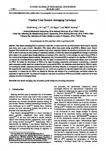
[email protected] ABSTRACT We proposed and demonstrated a novel time domain spectral phase encoding/decoding scheme by time domain stretching and high speed phase modulating short optical pulses. 16chips, 40GHz/chip optical codes have been generated and recognized successfully using long chirped fibre Bragg grating (LCFBG) as dispersive components, respectively. Transmission experiments have been carried out successfully with 2.5 Gbps over up to 50 km SMF. Keywords: Fibre optics and optical communications; Phase modulation; Multiplexing; Pulse shaping; Encoding/decoding; Optical code division multiple access. 1. INTRODUCTION In optical code division multiple access (OCDMA) system, many users share the same transmission medium by assigning unique pseudo-random optical code (OC) to each user. OCDMA is attractive for next generation broadband access networks due to its features of allowing fully asynchronous transmission with low latency access, soft capacity on demand, protocol transparency, simplified network management as well as increased flexibility of QoS control and enhanced confidentiality in the network [1~6]. Particularly, coherent OCDMA technique, where encoding and decoding are performed based on the phase and amplitude of optical field of the ultra-short optical pulses either in time domain or in spectral domain, is receiving much attention for the overall superior performance over incoherent OCDMA and the development of compact and reliable en/decoders (E/D) [7~15]. The coherent spectrally phase encoding time-spread (SPECTS) OCDMA system performs the en/decoding in spectral domain [8~12]. Figure 1 shows the working principle of the coherent SPECTS encoding/decoding scheme. In such a system, the encoding is done to the broad spectrum of the ultra-short optical pulse and different spectral component has different phase shift. The encoding results the spreading of the short pulse in time domain (time-spreading). The decoding is to give inverted phase changes to different spectral components by the proper decoder with a complementary phase shift pattern compared to encoder. Therefore, the autocorrelation for the proper code can recover the spectrum as well as the temporal shape of the original pulse, while the cross-correlation still spread in time similar as the encoded signals. The spectral phase encoding (SPE) scheme can also be applied in pulse shaping as well for applications such as high-repetition-rate pulse burst generation [19~20], RZ-to-NRZ converting [21] and etc. The SPECTS en/decoders include spatial lightwave phase modulator (SLPM) [9~10], high resolution phase encoder/decoder [8], micro-ring-resonator (MRR) [11] or monolithically integrated en/decoders including AWG and phase shifters [12]. Generally, in the SPECTS system, high spectral resolution is always desirable for the sake of the spectral efficiency [8]. As a limit, the resolution of each chip should equal to the mode spacing, or the repetition rate of the optical pulses [8, 21].
(b)
Input signal
Wavelength
t
Encoding
Decoding AutoAuto-correlation
Amplitude Phase: 0
0
Wavelength
π Wavelength
λ
CrossCross-correlation Amplitude 0
time
time
time
λ
Wavelength
Figure 1. Working principles of coherent SPETS encoding/decoding Therefore, the wavelength stability requirement for laser source and encoder/decoder is very stringent, which appears an issue for this system. Another issue is the compatibility of the encoder/decoders with the fiber optic system because most of them are based on free-space optics. The third issue with this scheme is the relatively high loss with these encoder/decoders.
Recently, spectral shaping to be done in time domain by stretching short pulse with dispersive components has also been demonstrated [21~22]. This time domain spectral shaping technique can be much flexible and compatible with fiber optic system. Recently, we have proposed and demonstrated a novel reconfigurable time domain SPE scheme for coherent OCDMA application [24-26]. 2. PROPOSED SPE SCHEME Figure 2 shows schematic diagram of the proposed reconfigurable time domain SPE scheme. The pulse generator generates ultra-short optical pulses, which have broadband spectrum. The SPE section is composed of a pair of dispersive devices with opposite dispersion values (–D and +D) and a high speed phase modulator (PM). The first dispersive device with dispersion value of D is to stretch the pulse in time domain, so that different spectral components of the signal spread at different positions in one bit duration. The PM is driven by OC patterns to modulate the phases of different spectral components. The second dispersive component with dispersion value of +D (opposite to the first one) is to compress the encoded signal and generate SPE signal. The SPE signal generated in this way can be decoded by conventional spectral phase decoders generating auto-/crosscorrelations for proper or improper OCs. SPE signal Intensity Intensity
Intensity
λ
λ
Time
Time
Intensity
λ
λ
Time
Time
Auto-cr
Time
Pulse generator
Cross-cr
Time
Time
Spectral phase encoding
Time
Spectral phase decoding
PC
Pulse generator
−D − dispersion
PM
+D + dispersion
Spectral phase decoder
Figure 2. Proposed SPE scheme The dispersive components can use single mode fibers (SMF) and dispersion compensation fibers (DCF), or long chirped fiber Bragg gratings (LCFBG). Conventional high speed PM can generate OC at 40 Gchip/s chip-rate. The potential advantages of the proposed SPE scheme include: 1. Good flexibility. This scheme offers fast (bitby-bit) OC reconfigurable capability, which is unique compared to conventional techniques. 2. Relaxed wavelength alignment requirement. The wavelength alignment for laser and encoder is done in time domain, the requirement is much lower compared to conventional schemes. 3. Simple configuration and good compatible with fiber optic system. This scheme can even be simplified by combining the SPE and data modulation with a single modulator. 4. Low loss and low cost. One probable issue of this scheme is that the data rate of the system is limited by the speed of the PM and the length of the OC. For a system with data-rate higher than 1 Gbps, the length of OC will have to be lower than 40-chip. But it should be enough for many OCDMA applications. . The decoding section has the same configuration as the SPE but the phase modulator was driven by the complementary code OC [25]. 3. ENCODING/DECODING EXPERIMENT WITH LCFBG Figure 3 shows the experimental setup using LCFBG as the dispersive components. The 1.9ps optical pulse trains with center wavelength of 1550.28nm was generated by a mode locked laser diode (MLLD) at repetition rate of 10GHz. An intensity modulator (IM) driven by a pseudo random bit sequence (PRBS) data was used to
Figure 3 Experimental setup of the SPED scheme using LCFBG
modulate the signal and generate 2.5Gbps OOK data. A phase modulator driven by 16 chips, 25ps/chip (40Gchip/s) optical code patterns (corresponding to 16chips, 40GHz/chip spectral code patterns) then phase modulates the stretched optical pulse. Five different optical codes OC1~OC5 patterns have been tested in the experiment: 111000100110101, 1010101010101010, 1111000011110000, 11111111 00000000 and 1110101100100010. Figure 4 shows the spectrum (upper trace) and waveform (middle trace) of the encoded signal, and the waveform of the decoded signal (lower trace) for the five codes. The decoded signals exhibit well defined auto-correlation peak with pulse width of ~2.49ps, 2.32ps, 2.57ps, 2.57ps and 2.26 ps, respectively. The red lines in each figure of the lower trace are for the original input pulse. The broadening of the decoded pulse is negligible in the experiment which verifies the excellent decoding performance of the SPED scheme with LCFBG.
Figure 4 Encoded spectrum (upper), waveform (middle) and decoded waveform (lower) for five codes 4. DATA TRANSMISSION EXPERIMENT In the transmission experiment, 2.5Gbps PRBS OOK data was generated by the intensity modulator before the SPE and transmitted over 50 km single mode fiber (SMF) and dispersion compensation fiber (DCF). The BER for the back-to-back (B-to-B) and transmission cases are shown in Figure 5. The BER performance for all the codes are almost identical. Error free transmission (BER