IEICE TRANS. COMMUN., VOL.E100–B, NO.5 MAY 2017
865
PAPER
Null-Space Expansion for Multiuser Massive MIMO Inter-User Interference Suppression in Time Varying Channels Tatsuhiko IWAKUNI†a) , Kazuki MARUTA† , Members, Atsushi OHTA† , Yushi SHIRATO† , Senior Members, Takuto ARAI† , and Masataka IIZUKA† , Members
SUMMARY This paper proposes a null-space expansion scheme for multiuser massive MIMO transmission in order to suppress inter-user interference (IUI) triggered by the temporal variation of the channel. The downlink multiuser MIMO channel capacity of time varying channels is severely degraded since IUI must be suppressed at the transmitter side by using past estimated channel state information at the transmitter side (CSIT). Massive MIMO has emerged as one of the most promising technologies for further capacity enhancement by increasing the number of base station (BS) antenna elements. Exploiting the excess degrees of freedom (DoFs) inherent in massive MIMO, a BS with the proposed IUI suppression scheme performs multiple null-steering for each UE (User Equipment) antenna element, which expands the null-space dimension. Computer simulations show that the proposed scheme has superior IUI suppression performance to the existing channel prediction scheme in time varying channels. key words: inter-user interference, channel time variation, multiuser MIMO, massive MIMO, null-space expansion
1.
Introduction
The recent spread of wireless communication devices such as smart phones and tablet PCs increases not only data traffic but also the number of user equipment (UEs) accommodated by each base station (BS). Frequency resources are limited and shared by many kinds of wireless communication systems such as Wi-Fi, WiMAX and LTE(-Advanced). Super wideband transmission in higher frequency bands such as SHF (Super High Frequency) or EHF (Extremely High Frequency) bands is another approach to increasing the transmission capacity [1], [2]. However, higher transmission power is required since the propagation loss is significant in the higher frequency bands. Unfortunately, it is difficult to realize cost-effective high power amplifiers (HPAs), thus massive MIMO is one of the most promising ways of achieving large beamforming gain; it offers a huge number of arrayed antenna elements while using relative low cost and low power amplifiers [3]–[5]. To accommodate many UEs and to realize high-capacity wireless communication, multiuser MIMO (Multiple-Input Multiple-Output) is effective [6]–[8]. In general, UEs have fewer antenna elements than the BS, and the number of UE antenna elements restricts the maximum number of spatially multiplexed streams in single-user MIMO. In multiuser Manuscript received March 31, 2016. Manuscript revised September 21, 2016. Manuscript publicized November 21, 2016. † The authors are with NTT Access Networks Service Systems Laboratories, NTT Corporation, Yokosuka-shi, 239-0847 Japan. a) E-mail:
[email protected] DOI: 10.1587/transcom.2016EBP3136
MIMO transmission, however, plural streams for plural UEs are multiplexed at the same time and same frequency which avoids the restriction. In downlink multiuser MIMO transmission, the BS requires the channel state information at the transmitter side (CSIT) and generates only 1 null per UE to suppress inter-user interference (IUI). The actual channel state generally varies due to the movement of UEs or objects around the UE. This degrades CSIT accuracy, which causes IUI through inaccurate null-steering, and a degradation in multiuser MIMO capacity [9]. Channel prediction techniques have been researched for multiuser MIMO in the time varying channel environment [11], [12]. In this approach, the future channel is predicted by some algorithm from past CSIT estimates. Transmission weights which will suppress IUI are calculated by this predicted channel. Since multiuser MIMO transmission with channel prediction still steers only 1 null per UE, its IUI suppression accuracy is limited, especially in high mobility situations. Another study has targeted the optimization of the antenna array arrangement [13]. Robust mutiuser MIMO transmission can be realized by a non-uniform linear array arrangement that provides high BS antenna correlation and reduces the channel variation effect. However, it is difficult to optimize the antenna array arrangement of massive MIMO systems because they have so many antenna elements. As mentioned above, massive MIMO is attractive due to its potential created by its extremely high degrees of freedom (DoFs). Null-space expansion for multiuser massive MIMO has been proposed [14] to suppress IUI caused by channel time variation exploiting the excess DoFs. This paper further evaluates the performance of our proposed scheme, especially under the presence of additive noise i.e. signal-to-interference power ratio (SINR) performance. This paper is organized as follows. The next section addresses the problem of multiuser MIMO in time varying channels. Section 3 describes the proposed null-space expansion scheme. Computer simulation results are shown in Sect. 4. Finally, this paper is concluded in Sect. 5. In this paper, normal letters represent scalar quantities, bold lowercase letters indicate vectors and uppercase letters indicate matrices. 2. System Model and Problem Definition This paper evaluates the performance of downlink multiuser
Copyright © 2017 The Institute of Electronics, Information and Communication Engineers
IEICE TRANS. COMMUN., VOL.E100–B, NO.5 MAY 2017
866
MIMO transmission in time varying channels. We assume the typical case that each UE has only 1 antenna element to make the discussion simple. Precoding is performed using CSIT estimated from the pilot sequence of uplink transmitted signals or feedback information from UEs. When NBS BS antenna elements and NU E UEs with single antenna element are used to multiplex multiple streams in the same frequency channel, the downlink channel matrix H ∈ C N B S ×NU E is represented as; h11 *. .. .. . . H = .. hi1 .. .. . . h , NU E 1 ( = hT1 · · ·
... .. .
h1j hi j
... hTi
...
h1N B S .. .
..
h NU E j
. ...
hi N B S .. .
···
hTNU E
h NU E N B S )T ,
+/ // // // // (1)
where hi j denotes the channel coefficient from the j-th BS antenna to the i-th UE and h i = (hi1, hi2, . . . , hi N B S ) ∈ C1×N B S represents the channel vector for the i-th UE. The multiuser MIMO transmission weight W ∈ C NU E ×N B S is expressed as; w11 ... w1j ... w1N B S *. .. .. . .. .. . . . wi j wi N B S W = .. wi1 .. .. .. .. . . . . w . . . w . . . w N 1 N j N UE UE U E NB S ,( ) = w 1 · · · w i · · · w NU E ,
T
+/ // // // // (2)
where w i = (wi1, wi2, . . . , wi N B S )T ∈ C N B S ×1 is the precoding weight vector for the i-th UE that satisfies: h i w k , 0 (i = k), h i w k = 0 (i , k).
(3) (4)
Equation (3) specifies the signal that should be transmitted to the objective UE. Equation (4) specifies the interference that should suppressed by the weight. In the time varying channel condition, the channel vector can be expressed by original component h i and time varying factor e i ; h˜i = ρh i + ei .
(5)
ρ is a real valued coefficient. Weight vector w i cannot be orthogonal to h˜i , h˜i w k = ( ρh i + ei )w k = 0 + ei w k , 0 (i , k).
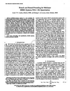
3. Null-Space Expansion Scheme for Multiuser Massive MIMO 3.1 Null-Space and Its Dimension In massive MIMO systems, the BS has a lot more antennas than the total number of multiplexed UE antennas, i.e. NBS ≫ NU E . Therefore, excess DoFs are available at the BS side. Such DoFs, equaling total number of UE antennas, are conventionally used for 1 null-steering per UE and the remaining DoFs are used to obtain beamforming gain. This beamforming gain provides high reception signal power while keeping the interference level constant which improves signal-to-interference power ratio (SIR) performance. In other words, the excess DoFs reduce the effect of IUI relatively [10]. However, just 1 null is steered toward each UE, so the absolute amount of IUI is not reduced. Our proposed null-space expansion scheme utilizes some excess DoFs to further enhance interference suppression by reshaping the beam pattern as shown in Fig. 1. In Fig. 1, the beam patterns for the conventional and proposed null steering are plotted using blue and red lines, respectively. While the position shift of the 1st UE causes IUI as shown by the blue line on purple arrow direction, multiple null steering reduces the IUI level more strongly as shown by the red line. It achieves effective IUI suppression at the cost of a slight drop in desired signal power. The principle of the null-space expansion scheme is described in Fig. 2. We first define the “null-space” as a vector subspace to be orthogonalized to the interference channel vectors. When we focus on the 2nd UE, the null-space obtained by the conventional precoding weight w 2 and that by the proposed null-space expanded weight w 2′ are shown in Fig. 2(a) and Fig. 2(b), respectively. The null-space dimension of the conventional weight vector is 1 since vector w 2 is designed to be orthogonal only to vector h i as shown in Fig. 2(a). Equation (4) can be still satisfied for the vector αh i which is obtained by multiplying h i : αh i w k = 0 (i , k) by arbitrary coefficients α. The null-space dimension of expanded weight w k′ is 2 because it is calculated to be orthogonal to the channel vectors h i and h i′; h i w k′ = 0 (i , k), h i′ w k′ = 0 (i , k).
(6)
As indicated above, discrepancy between the estimated channel and the real channel causes IUI. A IUI suppression technique is required that can enhance the total transmission capacity even in time varying channels [9]. Fig. 1
The concept of null-space expansion.
(7) (8)
IWAKUNI et al.: NULL-SPACE EXPANSION FOR MULTIUSER MASSIVE MIMO INTER-USER INTERFERENCE SUPPRESSION IN TIME VARYING CHANNELS
867
0.4 dB, while the 4-dimensional null-space of each UE suppresses IUI effectively and a huge SIR improvement can be expected. 3.2 Weight Calculation Procedure To obtain the precoding weight vectors for IUI suppression, there are several orthogonalization schemes such as zero forcing (ZF), minimum mean square error (MMSE) and Gram-Schmidt procedure. Our proposal scheme can yield arbitrary orthogonalization schemes as shown by the following procedure. We first expand the channel matrix by inserting additional channel vectors h k′ (k , i) as follows; Hi′ = Fig. 2
′T T (hTi , hT1 , h 1′T , · · · , h i−1 , hTi+1, · · · , hTNU E , h ′T NU E ) ,
The null-space generated by each precoding weight.
Channel vector h i′ is, for example, the predicted channel vector or the second latest estimated channel vector. The null-space provided by weight vector w k′ can be called “2dimensional null-space” since the weight vector is orthogonal to the 2 vectors of h i and h i′ as shown in Fig. 2(b). Null-spaces of even higher dimension can be obtained by using further excess DoFs to effect additional null-steering. The following relationship is satisfied in our proposed scheme; (αh i + βh i′ )w k′ = 0 (i , k),
(9)
where α and β are arbitrary coefficients. The linear combination of 2 channel vectors, αh i + βh i′ forms a planar 2-dimensional subspace. This means that precoding weight w k′ is designed to be orthogonal to the planar null-space whose dimension is much larger than that of conventional weight w k . The proposed scheme uses this expanded null “space” to suppress IUI though only 2 “points” null-steering is performed as shown in Fig. 1. It should be noted that the dimension of the channel vectors equals the number of BS antennas and is much wider than the 3 dimensional real space. Therefore, Fig. 1 only illustrates the concept of the proposed scheme by broadening the nulls. Additional null-steering provides slight transmission power loss. Consider the case of a BS with 100 antenna elements communicating with 4 UEs, each with 1 antenna element, simultaneously. In conventional massive MIMO, a 1-dimensional null-space is created for each UE. Hence the 100 − (4 − 1) = 97 DoFs are used to obtain beamforming gain. If 3 additional null-steering operations are performed for each UE (i.e. a 4-dimensional null-space is formed at each UE), the remaining 100 − (4 − 1) × 4 = 88 DoFs are used for beamforming. The signal power degradation is calculated in decibels as follows; ( ) 88 10 × log10 = −0.4 [dB]. (10) 97 Therefore, the expected degradation in signal power is only
(11)
where Hi′ ∈ C(2NU E −1)×N B S is an expanded channel matrix for the i-th UE. It is noted that h i′ is not inserted so as not to reduce the desired signal power for the i-th UE. Temporary precoding weight matrix Wi′ ∈ C N B S ×(2NU E −1) is calculated from the arbitrary orthogonalization scheme; Wi′ = (i) (i) ′ (i) (w i(i), w 1(i), w ′1(i), · · · , w ′i−1 , w i+1 , · · · , w (i) NU E , w NU E ), (12)
where w i(i) is the desired weight vector orthogonal to vectors h k and h k′ where k , i. The temporary precoding weight matrix Wi′ satisfies the condition that Hi′Wi′ becomes a diagonal matrix. The other vectors of Wi′ cannot be used for the other UE’s weight vector since they steer nulls to inserted channel vectors and reduce the desired signal power, e.g. w 1(i) (i , 1) cannot be used for the 1-st UE because it steers the null to h 1′ . Null-space expanded precoding weight matrix W′ is obtained as a combination of the desired weight vectors for each UE; UE ) W′ = (w 1(1), · · · , w i(i), · · · , w (N NU E ).
(13)
As mentioned above in Eq. (5), the channel state at any transmission instance includes the time varying factor ei . The channel matrix at the transmission instance can be expressed as a combination of the channel vectors including time varying factor; ˜ = ( h˜ T1 , · · · , h˜ Ti , · · · , h˜ TN )T . H UE
(14)
Effective channel matrix is obtained as product of the channel ˜ ′. It defines the desired signal and and weight matrices; HW the IUI component observed in UE side at any transmission instance. IUI component is calculated as, h˜i w k(k) = ( ρh i + ei )w k(k) = 0 + e i w k(k) (i , k).
(15)
In this equation, ei w k(k) is IUI leakage. Null-space of w k(k) is wider than that of w k in Eq. (6) since the additional nullsteering is performed. Therefore, IUI level in Eq. (15) is expected to be much smaller than the conventional in Eq. (6).
IEICE TRANS. COMMUN., VOL.E100–B, NO.5 MAY 2017
868 Table 1
3.3
The Relationship between Channel Prediction and Null-Space Expansion
In practice, w i must be calculated from estimated values of h i and h i′. Moreover, h i′ must also be derived from h i at the BS side. One example is the channel prediction technique described in Sect. 1. Here, we discuss the relationship between the proposed scheme and a channel prediction technique with linear extrapolation. In linear extrapolation, future channel vector hˆ i (t 0 + δt) is calculated as follows [11]; hˆ i (t 0 + δt) = h i (t 0 ) +
δt (h i (t 0 ) − h i (t −1 )), (16) t 0 − t −1
Simulation parameters.
Parameters
Values
Frequency Cell BS Antenna Array
20 GHz Sector = 120◦ Radius = 20 m 100 elements (10 × 10), Uniform planner array with half-wavelength spacing Directional antenna [15] HPBW=65◦ (Vertical/Horizontal) 4 (omnidirectional 1 element / 1 UE) 4, 40 km/h ( fD TS = 4.9 × 10⁻⁴, 4.9 × 10⁻³ ) Rician fading, K = 10[dB] 200 symbols (1.3 msec) 6.67 µsec Zero Forcing (ZF) Linear Extrapolation
BS Antenna Element Number of UEs NU E UE Speed Channel Model Channel Estimation Period Symbol Length MIMO Weight Channel Prediction
this can be rewritten as, hˆ i (t 0 + δt) = αh i (t 0 ) + βh i (t −1 ).
(17)
The right hand side of Eq. (17) is the same expression as (αh i + βh i′ ) in Eq. (9). When weight vector w k′ is orthogonal to channel vectors h i (t 0 ) and h i (t −1 ), hˆ i (t 0 + δt)w k′ = 0,
(18)
holds for any α and β. This means that null-steering to past channel vectors in our proposed scheme automatically yields null-steering to the future (predicted) channel vectors with arbitrary value for δt. In contrast, since Eq. (16) includes the value of time difference δt, the conventional channel prediction technique is available only for a specific predicted channel with a certain time difference. Even though the time varying channel can be obtained by Eq. (16), the use of an erroneous δt value causes IUI. Because there is no guarantee that the speed of CSIT variation is constant within the CSIT feedback period, this issue is a significant problem. In addition, when data is transmitted many times within the CSIT feedback period, weight calculation is required at each transmission timing to maintain CSIT accuracy. The proposed scheme performs the weight calculation only once after channel estimation since the expanded null-space contains all predicted channel vectors on the linear line described in Eq. (16). 4.
Computer Simulations
4.1
Simulation Parameters
Simulation parameters are shown in Table 1. A small cell with high frequency band signals is modeled as shown in Fig. 3. The height difference between the BS and UEs is assumed to be 10 m. 4 UEs are uniformly distributed in the sector cell. The UEs move in random directions at constant velocity. We assume a Nakagami-Rice fading channel with Rician factor, K = 10 dB. Channel matrix H is expressed as follows; √ √ K 1 H= H LoS + H N LoS, (19) K +1 K +1
Fig. 3
Simulated cell configuration.
where H LoS is determined by the spatial relationship of the BS antenna elements and UE antenna elements. H N LoS represents the multipath component from the scatterers, which are uniformly distributed in angle around the UEs. To consider the spatial correlation between BS antenna elements, independent identically distributed (i.i.d.) Rayleigh fading channels generated by Jakes’model [16] are converted into correlated channels using the Kronecker model [17]. ( )H H N LoS = Rr1/2 Hiid R1/2 , (20) t where Rt is calculated by the approximate formula in [18]. The Power Azimuth Spectrum (PAS) is set to 5◦ . The following three precoding schemes are compared. (a) Conventional multiuser massive MIMO scheme (b) Channel prediction scheme with linear extrapolation (c) Proposed null-space expansion scheme Unless otherwise noted, the null-space dimension of (c) the proposed scheme is set to be 2, i.e. the nulls are directed to the past 2 estimated channels. Total transmission power is assumed to be constant and is normalized by the number of multiplexing UEs and BS antenna elements. We evaluate SIR and SINR performance. The SIR is calculated at every symbol transmission timing as shown in Fig. 4. In (a) the conventional scheme and (c) the proposed scheme, the precoding weight is calculated at the instance of CSI estimation. In (b) the channel prediction scheme, the channel is predicted at every symbol transmission timing along with the precoding weight. CSI is estimated every 200 symbols and is assumed to be ideal,
IWAKUNI et al.: NULL-SPACE EXPANSION FOR MULTIUSER MASSIVE MIMO INTER-USER INTERFERENCE SUPPRESSION IN TIME VARYING CHANNELS
869
Fig. 5
Fig. 6
SIR performance of each weight calculation method.
The relative signal and interference power distribution.
tion. Fig. 4
SIR calculation flow of each weight calculation scheme.
i.e. CSI estimation error due to the receiver noise is not considered in order to precisely assess the impact of the channel time variation. 4.2
Simulation Results
Figure 5 plots the cumulative distribution functions (CDFs) versus SIR. The proposed null-space expansion scheme exhibits the best SIR performance at the movement speeds of 4 km/h and 40 km/h. When the speed is 4 km/h, the proposed null-space expansion scheme improves the CDF 50% values of the SIR by over 15 dB and 3 dB compared to the conventional scheme and the channel prediction scheme, respectively. When the speed is 40 km/h, the performance of the channel prediction scheme is almost equal to that of the conventional scheme. It is notable that the null-space expansion proposal improves the CDF 50% value of the SIR by about 5 dB even in this severe time varying channel condi-
Figure 6 plots the CDFs versus the relative signal and interference powers. The powers are normalized to 0 dB in the SISO (Single-Input Single-Output) case. The signal power obtained by the proposed null-space expansion scheme is slightly degraded compared to the others but interference power is suppressed significantly. It can be seen that the IUI suppression effect is much greater than the signal power loss. Comparing the channel prediction scheme with the proposed scheme, the signal power is reduced by about 1 dB but the interference power is suppressed by over 5 dB (CDF 50%) at 4 km/h. In the case of UE speed of 40 km/h, while the channel prediction scheme lost its IUI suppression gain, the proposed scheme maintained it. The IUI suppression gain of the proposed scheme compared to the channel prediction scheme was maintained even though the speed was 10 times greater. This result validates the principle of the proposed scheme as discussed in Sect. 3. Note that the exact value of the signal power loss and the interference power suppression depend on the spatial correlation between BS antenna elements and UEs. Figure 7 shows the time variation of SIR for CDF 50%. In this figure, the channel estimation is performed at the time
IEICE TRANS. COMMUN., VOL.E100–B, NO.5 MAY 2017
870
Fig. 7
Time variation of CDF 50% values of SIR.
Fig. 8
SIR versus UE speed.
of 0 seconds, so SIR is relatively high just after 0 seconds. The SIR values degrade with time in each scheme, however, the proposed scheme keeps the SIR values higher. This shows the effect of the wider null-space with additional nullsteering. Figure 8 shows the SIR values of CDF 50% and CDF 5% versus UE speed. Though all SIR plots degrade at higher speed, the proposed scheme always outperforms the other schemes. Channel prediction is also effective in suppressing IUI at the low speed condition, but its gain decreases rapidly as UE speed increases. For speeds over 16 km/h, its SIR becomes worse than that of the conventional scheme. Hence the proposed scheme is quite effective and stable even in high mobility environments. In the above evaluations, 1 additional null-steering operation is performed for each UE, that is, the expanded nullspace has dimension of 2. This null-space dimension can be further expanded if the BS antenna has sufficient DoFs remaining. Figure 9 plots SIR values versus null-space dimension, N. In this figure, N = 1 means the conventional multiuser massive MIMO case. In other cases, the channel matrix is constructed by the newest CSIT and N − 1 past
Fig. 9
SIR versus null-space dimension per UE.
Fig. 10
Channel correlation versus time progress.
CSITs. SIR values increase with the null-space dimension. In this evaluation, DoFs are still enough even if the dimension is 10 because the BS has 100 antenna elements. When 4 UEs are multiplexed and 10 nulls are generated to each UE, the DoF consumption is (4 − 1) × 10 = 30. It is still much lower than the available DoFs of 100. From this figure, it can be concluded that our proposed scheme can suppress the IUI with additional null-steering provided the BS has enough DoFs. Above results have shown that utilizing the past CSI estimates can expand null-space including future channel state and contributes to improve SIR performance. To analyze this mechanism, channel correlation in time progress is plotted in Fig. 10 and it is obtained as follows; ρ(t) =
h i (0)h iH (t) ||h i (0)||||h iH (t)||
.
(21)
Figure shows the one simulation trial and average value when UE speed is 4 km/h. Although the channel correlation value is fluctuated, its average value converges to about 0.7. It leads the fact that the channel vector is moving in a certain dominant vector sub-spaces. When the sub-space dimension
IWAKUNI et al.: NULL-SPACE EXPANSION FOR MULTIUSER MASSIVE MIMO INTER-USER INTERFERENCE SUPPRESSION IN TIME VARYING CHANNELS
871
Fig. 12
Fig. 11
SINR of the each weight calculation method versus SNR.
is more than 1, the correlation value may become smaller than 1. Meanwhile, the correlation value recovers with time and it can be expected that the sub-spaces are maintained for a long period. IUI leakage can be strongly suppressed if we can accurately estimate the dominant vector sub-spaces. Exploiting the above fact that the time correlation of the dominant vector sub-spaces can be kept during several CSI estimation period, our proposed scheme works to find such vector sub-spaces using a set of past CSI estimates. Note that the actual IUI suppression effect is limited by noise. Figure 11 plots the SINR versus the received SNR to clarify the applicable region of the proposed scheme. The SNR, horizontal axis, is the received SNR in SISO case. In this figure, the speed of each UE is set to 4 km/h and 40 km/h, a 2-dimensional null-space is formed for each UE. When UE speed is 4 km/h and the SNR is lower than 10 dB, the schemes have similar performance. This is because the noise is more dominant than the IUI, so the IUI suppression effect is negligible. However, when the SNR is higher than 20 dB, i.e. IUI dominant region, the proposed scheme
SINR versus the null-space dimension per UE antenna.
shows high SINR performance. When UE speed is 40 km/h, the IUI caused by channel time variation becomes significant. The proposed scheme shows outstanding SINR performance compared to the conventional and channel prediction schemes when the SNR is larger than 0 dB; the channel prediction scheme matches the performance of the conventional scheme. Considering the small cell scenario in future radio systems, it is expected that the SNR will be larger than 0 dB in most cases. Finally, Fig. 12 plots SINR versus the dimension of nullspace, N at the condition of SISO SNR=20 dB. The SINR improvement possible with N = 2 and N = 5 saturates at speeds of 4 km/h and 40 km/h, respectively. Over the saturation point, SINR performance degrades as the dimension increases. This is because increasing the null-space dimension uses some the DoFs originally used for beamforming gain, which degrades objective signal power. Thus, adaptive null-space dimension control that considers the amount of channel variation is effective to maximize SINR performance since the saturation point depends on UE speed. As described in Sect. 4.1, the additive noise effect in channel estimation i.e. channel estimation error caused by the receiver noise is not considered in the simulations. It degrades the accuracy of CSIT as same as conventional schemes and results in the inaccurate null-steering. Although null-space expansion effect will be reduced in practical, it should be further investigated with channel estimation techniques. In these evaluations, channel estimation period is set to 1.3 msec as an example. However, it is difficult to estimate the CSI of all UEs when the BS accommodates many UEs. Increasing the estimation period increases the impact of channel time variation, which equals an increase in UE speed. Our proposed scheme is effective in such conditions because our scheme suppress IUI even in high mobility environments. 5. Conclusion The main objective in applying massive MIMO is generally
IEICE TRANS. COMMUN., VOL.E100–B, NO.5 MAY 2017
872
to attain higher beamforming gain, however, the many elements can be controlled separately and thus used to suppress interference more strongly. This paper utilizes the excess DoFs available with massive MIMO, to propose a novel IUI suppression scheme, named null-space expansion, for multiuser massive MIMO systems with time varying channels. The null-space expansion scheme suppress IUI through higher order null-steering. The proposal steers multiple nulls to each UE antenna. We discussed how the multiple nulls expand the null-“space dimension” in channel vector space. We also compared our scheme with the channel prediction technique, and showed that our scheme can assess past channels to predict all null-steering for future channels with linear extrapolation. Computer simulations showed that the proposed scheme suppresses IUI effectively, and significantly outperforms the existing linear extrapolation technique in exchange for a slight signal power loss. It was confirmed that expanding the null-space further enhances SIR performance. We can conclude that the proposed null-space expansion scheme is the most promising solution to realize multiuser MIMO in realistic time varying channel environments.
[12]
[13]
[14]
[15] [16] [17]
[18]
Commun., vol.E97-B, no.12, pp.2747–2755, Dec. 2014. DOI: 10.1587/transcom.E97.B.2747 A. Duel-Hallen, “Fading channel prediction for mobile radio adaptive transmission systems,” Proc. IEEE, vol.95, no.12, pp.2299–2313, December 2007. DOI: 10.1109/JPROC.2007.904443 T. Ishihara, K. Sakaguchi, S. Sampei, and G.K. Tran, “Base station antenna configuration for robust MU-MIMO,” Proc. ICCS’14, pp.517–521, Nov. 2014. T. Iwakuni, K. Maruta, A. Ohta, Y. Shirato, T. Arai, and M. Iizuka, “Inter-user interference suppression in time varying channel with null-space expansion for multiuser massive MIMO,” Proc. IEEE PIMRC’15, pp.660–664, Hong Kong, China, Aug. 2015. 3GPP, TR36.873 (V1.0.0), Sept. 2013. W.C. Jakes, Microwave Mobile Communications, IEEE Press, 1974. K. Yu, M. Bengtsson, B. Ottersten, D. McNamara, P. Karlsson, and M. Beach, “Modeling of wide-band MIMO radio channels based on NLoS indoor measurements,” IEEE Trans. Veh. Technol., vol.53, no.3, pp.655–665, May 2004. DOI: 10.1109/TVT.2004.827164 WiMAX Forum, “Mobile Release 1.0 Channel Model,” June 2008.
Tatsuhiko Iwakuni received the B.E. degree in information communication engineering from the University of Electro-Communications, Tokyo, Japan, in 2011, and the M.E. degree in electrical, electronic and information engineering from Osaka University, Osaka, Japan, in 2013. In 2013, he joined NTT Access Network Service Systems Laboratories, where he has been engaged in research on multiuser massive MIMO systems. He is a member of the IEICE. He is currently in NTT Broadband Plat-
References [1] NTT DOCOMO, “DOCOMO 5G White Paper,” July 2014. [2] Y. Okumura, “5G mobile radio access system using SHF/EHF bands,”’ Proc. APMC’14, pp.908–910, Nov. 2014. [3] A.L. Swindlehurst, E. Ayanoglu, P. Heydari, and F. Capolino, “Millimeter-wave massive MIMO: The next wireless revolution?,” IEEE Commun. Mag., vol.52, no.9, pp.56–62, Sept. 2014. DOI: 10.1109/MCOM.2014.6894453 [4] E.G. Larsson, O. Edfors, F. Tufvesson, and T.L. Marzetta, “Massive MIMO for next generation wireless systems,” IEEE Commun. Mag., vol.52, no.2, pp.186–195, Feb. 2014. DOI: 10.1109/MCOM.2014.6736761 [5] T. Obara, S. Suyama, J. Shen, and Y. Okumura, “Joint processing of analog fixed beamforming and CSI-based precoding for super high bit rate massive MIMO transmission using higher frequency bands,” IEICE Trans. Commun., vol.E98-B, no.8, pp.1474–1481, Aug. 2015. DOI: 10.1587/transcom.E98.B.1474 [6] Q.H. Spencer, C.B. Peel, A.L. Swindlehurst, and M. Haardt, “An introduction to the multi-user MIMO downlink,” IEEE Commun. Mag., vol.42, no.10, pp.60–67, Oct. 2004. DOI: 10.1109/MCOM.2004.1341262 [7] K. Kusume, G. Dietl, T. Abe, H. Taoka, S. Nagata, “System level performance of downlink MU-MIMO transmission for 3GPP LTEadvanced,” Proc. VTC’10-Spring, pp.1–5, May 2010. [8] D. Gesbert, M. Kountouris, R.W. Heath, Jr., C.B. Chae, and T. Salzer, “From single user to multiuser communications: Shifting the MIMO paradigm,” IEEE Signal Process. Mag., vol.24, no.5, pp.36–46, Oct. 2007. [9] H.P. Bui, Y. Ogawa, T. Nishimura, and T. Ohgane, “Performance evaluation of a multi-user MIMO system with prediction of timevarying indoor channels,” IEEE Trans. Antenn. Propag., vol.61, no.1, pp.371–379, Jan. 2013. DOI: 10.1109/TAP.2012.2214995 [10] T. Iwakuni, K. Maruta, A. Ohta, Y. Shirato, S. Kurosaki, T. Arai, and M. Iizuka, “Massive MIMO effect for multiuser spatial multiplexing in time varying channel,” IEICE Commun. Express., vol.4, No.8, pp.270–275 Aug. 2015. DOI: 10.1587/comex.4.270 [11] K. Yamaguchi, H.P. Bui, Y. Ogawa, T. Nishimura, and T. Ohgane, “Channel prediction techniques for a multi-user MIMO system in time-varying envrionments,” IEICE Trans.
form, Inc.
Kazuki Maruta received the B.E., M.E. and Ph.D. degrees in engineering from Kyushu University, Japan in 2006, 2008 and 2016, respectively. Since joining NTT Access Network Service Systems Laboratories in 2008, he has been engaged in the research and development of interference compensation techniques for future wireless communication systems using cooperative MIMO, massive MIMO, high-efficient wireless multihop relay and adaptive array signal processing. He is currently an assistant professor in the graduate school of engineering, Chiba University. He received the Young Researcher’s Award from the IEICE in 2012, IEICE Radio Communication Systems (RCS) Active Researcher Award in 2014 and Asia-Pacific Microwave Conference (APMC) 2014 Prize. He is a member of the IEICE, IEEJ and IEEE.
IWAKUNI et al.: NULL-SPACE EXPANSION FOR MULTIUSER MASSIVE MIMO INTER-USER INTERFERENCE SUPPRESSION IN TIME VARYING CHANNELS
873
Atsushi Ohta received the B.S. and M.S. degrees in Physics from Chiba University, Chiba, Japan, in 1988 and 1990, respectively. He joined NTT in 1990 and engaged in the development of multi-beam satellite communication systems. From 1997 to 2002, he engaged in the development of broadband wireless LAN system, named AWA (Advanced Wireless Access) and based on European standard, HiperLAN/2. From 2002 to 2008, his research interests included single and multi-user MIMO communication systems that offer improved utilization efficiency of radio frequency resources. He is currently researching and developing massive antenna systems for wireless entrance links (MAS-WE) in the Access Network Service Systems Laboratories, NTT. He received the Best Paper Award in 2009 from the IEICE.
Yushi Shirato received the B.E. and M.E. degrees in electrical engineering from Tokyo University of Science in 1990 and 1992, respectively. Since joining NTT Wireless Systems Laboratories in 1992, he has been engaged in the R&D of adaptive equalizers, modems for fixed wireless access systems, and software defined radio systems. He is currently engaged in R&D of flexible wireless systems. He received the Young Engineer’s Award from IEICE in 2000 and the 18th Telecom System Technology Award from the Telecommunications Advancement Foundation. He is a member of IEICE.
Takuto Arai received the B.E. and M.E. degrees in computer science and engineering from Waseda University, Japan in 2010 and 2012, respectively. Since joining NTT Access Network Service Systems Laboratories in 2012, he has been engaged in the research and development of massive MIMO techniques for wireless access systems. He is a member of the IEICE and IEEE. He is currently in NTT DOCOMO, Inc.
Masataka Iizuka received the B.E. and M.E. degrees from Tohoku University, Miyagi, in 1988 and 1990, respectively. In 1990, he joined NTT Radio Communications Systems Laboratories and studied radio channel control techniques for personal communications systems. From 1997 to 2006, his research focused on radio access control schemes for high speed wireless LANs. After completing the commercial development of a wireless LAN system based on IEEE802.11a, he engaged in the promotion of the Next-Generation Network system. He is currently a senior research engineer, supervisor, and Group Leader in the Wireless Access Systems Project, NTT Access Network Service Systems Laboratories, responsible for R&D of wide-area wireless access systems. He is a member of IEICE.