International Journal of Computer and Electrical Engineering, Vol. 2, No. 5, October, 2010 1793-8163
Numerical Computation of Lightning Induced Surges on Overhead Power Distribution Lines S. M. Abdur Razzak, M. Abdur Rashid, M. Z. I. Sarkar, Shiro Tamaki and M. Mortuza Ali
Abstract—This paper presents numerical computation of lightning induced surges on a overhead power conductor taking into account real earth conductivity. A modified dipole technique is used to compute lightning generated electromagnetic fields radiated from lightning return strokes. A modified Agrawal transmission line model is used to calculate interaction between the electromagnetic fields and the overhead power conductor based on the finite difference method. Induced overvoltage waveforms resulting in from a front return stroke current model are presented for different line heights. Validity of the new dipole technique as well as the modified Agrawal model is also tested. Index Terms—lightning induced surge, electromagnetic compatibility, finite difference computation, overvoltage phenomenon, and computational electro-magnetics.
I. INTRODUCTION Numerical simulation plays an essential role for theoretical studies of electromagnetic problems because of the complex nature of the electromagnetic waves. A close interaction between theory and practical works is crucial for every developing research field. Numerical computation of surge waveforms resulting in from lightning strokes is very important to know various aspects of the problems and equally important in developing protection schemes against such an atmospheric phenomena. Lightning surge related damages may arise either due to direct strokes or by the fields radiated from distant lightning i.e., indirect strokes. Direct lightning strokes are considered as a serious problem. However, indirect strokes, although less energetic than direct strokes, may be a significant problem because of their high frequency of occurrence. The later causes significant damages to electrical power system components, telecommunication equipments, and computer networks every year. These damages result in huge losses of capitals, Manuscript received January 28, 2010. S. M. Abdur Razzak is with the Electrical and Electronic Department, Rajshahi University of Engineering & Technology, Rajshahi-6204, Bangladesh (phone: 880-721-750356; fax: 880-721-750356; e-mail:
[email protected]). M. A. Rashid is with the Graduate School of Engineering & Science, University of the Ryukyus, Okinawa 903-0213, Japan (e-mail:
[email protected]). M. Z. I. Serker is with the Electrical and Electronic Engineering Department, Rajshahi University of Engineering & Technology, Rajshahi-6204, Bangladesh (
[email protected]. Tamaki Shiro is with the Graduate School of Engineering & Science, University of the Ryukyus, Okinawa 903-0213, Japan. M. Mortuza Ali is with the Electrical and Electronic Engineering Department, Rajshahi University of Engineering & Technology, Rajshahi-6204, Bangladesh (
[email protected]).
826
equipments, interruption of services, and increased operation and maintenance cost. Therefore, the need for adequate protection of electrical and electronic systems from radiated and/or conducted electromagnetic disturbances is becoming increasingly important [3]. For insulation design of the power lines and optimal design of effective and economic protection schemes for sophisticated electronic and telecommunication systems, it is very important to know the induced voltage behaviors. As a consequence, evaluation of lightning induced electromagnetic fields has been the subject of theoretical and experimental studies for the last few decades [4-11]. Although the techniques have long been studied, an agreement has not been reached yet in the methods of its evaluation [12]. Therefore, it is being reconsidered again in recent years [13-17]. Lightning induced electromagnetic fields have two major components, namely, horizontal fields and vertical fields. Each of them consists of three terms: electrostatic field, induction field, and radiation field. All these components are responsible for inducing voltage on an overhead conductor. In the previous works, the electromagnetic fields radiated from lightning discharges were calculated either by Sommerfeld integral method or by Wave-tilt function method [7, 18]. In both methods, the effects of electrostatic field and induction field were neglected, only the radiation field was considered to evaluate the induced voltages. As a result, the above methods are incapable to compute induced voltages when strike occurs in the vicinity of the line conductors. For strikes occurring at the close vicinity of the line conductor, the effects of induction and electrostatic field components are significant and therefore can’t be neglected. In this paper, the modified dipole technique is used to estimate electric fields. This new technique is capable of computing electromagnetic fields regardless of the striking point distance as this method takes into consideration all the three field components. Moreover, the dipole technique is computationally simple, robust, and eliminates the complicated frequency domain analysis of the Wave-tilt function or the time consuming evaluation of Sommerfeld Integrals. The finite difference method is used to solve the telegrapher’s equation using a modified Agrawal time domain model [4].
II. COMPUTATION OF ELECTROMAGNETIC FIELDS Two critical points in the calculation process for electromagnetic fields are the lightning channel model and handling the lossy ground effects. We consider a straight vertical return stroke lightning channel having the dipole
International Journal of Computer and Electrical Engineering, Vol. 2, No. 5, October, 2010 1793-8163
geometry and current waveform as shown in Fig. 1. Electric fields radiated from such a lightning channel current can be computed by solving the time varying Maxwell’s equations and are given by [17]-
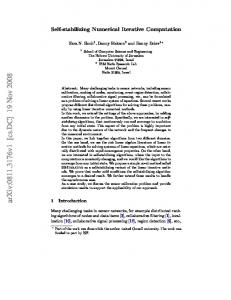
dipole technique evaluates ii(t) depending on the ground conductivity and therefore not the same as the source strength. III. SOURCE AND IMAGE CURRENT MODELS Figure 2 shows the source and image current and the effect of ground conductivity on the rise characteristics of the image current. The typical return stroke current waveform shown in Fig.1b can be given by the following mathematical expression i (t ) = I P [exp(−αt ) − exp( − βt ) (3) The image current ii(t) [17] can be calculated by taking the inverse Laplace transform of (4) and is given by the time domain equation (5). I i ( s ) = −(σ e / ε e ) 1 /( s + σ e / ε e I ( s ) (4)
[
]
where, I(s) and Ii(s) are, respectively, the Laplace transform of source and image current, σe and εe are respectively the ground conductivity and permittivity.
i i (t ) = − I P ( e − α t − e − β t ) + ⎡ ⎢σ I P (e −αt − e − βt ) ⎢ e× ⎢ ε e (σ e − α ) − ( σ e − β ) ⎢ εe εe ⎣ ⎤ −σ e t εe −αt − βt ⎥ e (α − β ) − e + e ⎥ − σe σe ( −α) − ( − β ) ⎥⎥ εe εe ⎦
(a)
Equation (5) can be rearranged as (6) to evaluate the image current for a ground conductivity of zero i.e., ground as an insulator. In this case there will be no image current which is depicted in Fig 2.
(b) Fig.1 (a) Lightning strike and dipole geometry, (b) Return stroke current waveform t dh ⎡ 2(h − z ) 2 dE z = ⎢ ∫0 i(h, t − R / c)dt 4πε 0 ⎣ R 5 2(h − z ) 2 − r 2 i ( h, t − R / c ) + cR 4 ⎤ r2 ∂ − 2 3 i ( h, t − R / c ) ⎥ c R ∂t ⎦
dE r =
(5)
ii (t) =
(1)
σe ⎡[e−αt − e−(σ / ε )t ] [e−βt − e−(σ / ε )t ]⎤ IP ⎢ − ⎥ εe ⎣ σe / εe −α σe / εe − β ⎦ e
e
e
e
(6)
The field at P(r, φ, h) for the small segment of channel is the vector sum of the fields due to source and image dipole and the total field can be obtained by integrating over the length of the channel.
t dh ⎡ 3(h − z ) i (h, t − R / c)dt ⎢ 4πε 0 ⎣ R 5 ∫0 3r (h − z ) (2) + i ( h, t − R / c ) cR 4 r (h − z ) ∂ ⎤ − 2 3 i ( h, t − R / c ) ⎥ c R ∂t ⎦
As we consider ground as a medium of finite conductivity, the electric field due to image source can be determined from (1) and (2) by simply replacing i(t) by ii(t). Where i(t) is the source current and the ii(t) is the image current. The modified 827
Fig.2 Effects of ground conductivity on rise time characteristic of image current waveform.
To cheek validity of the image current model, two extreme
International Journal of Computer and Electrical Engineering, Vol. 2, No. 5, October, 2010 1793-8163
cases were considered. In the first case, the ground is considered as an insulator (σ =0) and it is found that the electric field at P is only due to source current as expected. In the second case, the ground is considered as an infinitely conductive (σ =∞), in this case the source and image current will be same but opposite in polarity. The validity of the image current for the extreme cases ensures its usefulness for finite values of the earth conductivity.
V ( y, t + Δt ) = V ( y, t ) Δt Δy[I ( y + Δy, t ) − I ( y, t )] C − [hEzi ( y,0, t + Δt ) − hEzi ( y,0, t )] I ( y, t + Δt ) = I ( y, t ) −
Δt Δy[V ( y + Δy, t ) L Δt − V ( y, t )] − E yi ( y, h, t ) L −
IV. CALCULATION OF INDUCED VOLTAGES Original Agrawal [4] model has T-section representation of the transmission line. Here, П-section model is used to ensure symmetry in the calculation. Figure 3 shows the modified Agrawal model of transmission line. The transmission line is considered to be lossless and it is a good approximation for line length up to 3km depending on the ground conductivities. L and C are the unit length inductance and capacitance of the considered line respectively, l is the line length, h is the line height above the earth surface and R0 is the characteristic impedance.
(9)
(10)
Here, t+∆t denote incremental time and y+∆y denote incremental line length. The above equations are solved by finite forward difference method to calculate the induced voltage. Voltage at any position for the incremental time t+∆t is calculated from their own values, currents, and vertical electric field for present time t, and also for incremental time t+∆t along the overhead line by (9). Similarly, current at any position for the incremental time t+∆t is calculated from their own values, voltage and horizontal electric field for present time t, and also for incremental time t+∆t along the overhead line by (10). V. SIMULATION RESULTS
Fig. 3 Transmission line model.
The coupling between the electromagnetic fields produced by nearby return stroke current and overhead line in time domain can be expressed as-
∂V S ( y , t ) ∂I ( y , t ) +L = E yi ( y , h , t ) (7) ∂y ∂t ∂I ( y,t) ∂V S ( y,t) + C = 0 ∂y ∂t
The relative position of the overhead transmission line and strike points is shown in Fig. 4. A semicircle of radius D is considered from the centre of the line on the plane at the line height. Strike points are denoted by points 1 to 9. Point 1 which is on the extension of the line axis is called side return strike point and point 5 which is on the perpendicular bisector of the line is called the front return strike point. We consider that the return stroke current propagates upward with a constant velocity; the shape of the lightning current is an impulse of 1/20 μs, and the overhead line is lossless while the earth is homogeneous with constant conductivity and permittivity. Based on these parameters and considerations, Fig. 5 and 6 show simulation results.
(8)
where, I (y, t) is the line current, VS(y,t) is the scattered i
voltage and E y (y,h,t) is the horizontal component of the incident electric field along y-axis at the conductors height. It should be noted that the horizontal electric field interacts with vertical conductors and vertical electric field interacts with the horizontal conductor. The line is considered to be lay down along the y-axis on the z = h plane. Applying the boundary conditions for the scattered voltage, the differential voltage and current equations given in equations (7) and (8) can be expressed as equations (9) and (10) respectively-
828
Fig.4 Lightning strike points and power line orientation.
In Fig. 5, calculated pick induced voltages at every striking points are shown for three different line heights. It shows that a side return stroke induces more voltage than a front return stroke for the same parameters. The induced voltage magnitude decreases as the strike point moves toward the front return point on the semicircle. Fig. 6 shows voltage waveforms for strike at point 5 for three different line heights.
International Journal of Computer and Electrical Engineering, Vol. 2, No. 5, October, 2010 1793-8163
It shows that more the line height more is the induced voltage. The wave shape of the induced voltage is found similar to that calculated by Nucci et al. [8]. The difference in magnitude between the two calculations is due to difference in line, strike parameters and earth conductivity.
implement using computer software. There is scope to improve this method for calculating lightning induced voltages on multiconductor power. REFERENCES [1]
TABLE I: PARAMETER VALUES USED IN CALCULATION Name of the Parameter Values Line Length, l 1000 m Line Height, h 5, 10, 15 m Line Inductance, p.u., L 2.14 µH Line Capacitance, p.u., C 5.20 pF Peak Channel current, IP 12 kA Channel Current Velocity, v 300 m/µs Front time of the current, Tr 1.0 µs Tail Time of the current, Tf 20 µs Ground Conductivity, σ 0.03 S/m Ground Relative Permittivity, ε 10 εr Striking point distance, D 1000 m Cloud Height, H 4 km
Fig.5 Absolute peak induced voltage magnitude for lightning strikes at different points.
Fig.6 Induced voltage waveforms for lightning strike at the front return stroke point 5.
VI. CONCLUSION A new dipole technique based finite difference computation of lightning induced overvoltages on overhead power lines has been presented. For the purpose of demonstration of such a new technique, a single conductor unexcited power line has been considered. Mathematical expressions and simulation results have been presented. This method is computationally simple, accurate and easy to 829
Md. Ahsanul Alam, “The Study of Lightning Ground Flash Phenomena in Peninsular Malaysia”, M. Sc. Thesis, Faculty of Electrical Engineering, Universiti Teknologi Malaysia, February 1996. [2] K. Uehara and G. Ohwa, “Investigation of Lightning Damage on Distribution Lines”, IEEE Transactions on power Apparatus and Systems”, Vol. PAS-87, pp, 1018-1025, April 1968. [3] Condettina, Buccella, Saverio Cristina, “Frequency Analysis of the Induced Effects Due to the Lightning Stroke Radiated Electromagnetic Field”, Commission of European Communities-Directorate general for Science and Research Development, Brussels, Belgium, Jan. 25, 1991 [4] A. Agrawal et. al,” Transient response of multiconductor transmission line excited by a nonuniform electromagnetic field,” IEEE Trans. on EMC, vol.22, pp.119-129, 1980. [5] M. Ishii et. al.” Lightning-induced voltage on an overhead wire dependent on ground conductivity,” IEEE Trans. On Power Delivery, vol.9, no.1, pp.109-115, January 1994. [6] C.A. Nucci et al., “Influence of a lossy ground on Lightning induced voltages on overhead lines”, IEEE Trans. On EMC, Vol. 35, Feb. 1993. [7] M. Ishii, K. Michishita, Y. Hongo and S. Oguma,” Lightning-induced voltage on an overhead wire dependent on ground conductivity,” IEEE Trans. On Power Delivery, vol.9, no.1, pp.109-115, January 1994. [8] C.A. Nucci and F. Rachidi, “Lightning Induced Overvoltages”, IEEE Trans. And Dist. Conference, New Orleans, April, 14, 1999. [9] G. Diendorfer, “Induced voltages on an overhead line due to nearby lightning”, IEEE Trans. On EMC, Vol. 32, pp.292-299, November 1990. [10] V. Jankov, “Estimation of the maxital voltage induced on an overhead line due to nearby lightning”, IEEE Trans. On Power Delivery 12(1) (1997) 315-324 January. [11] K. Michishita and M. Ishii,” Lightning induced overvoltages on overhead wires influenced by inclined return stroke channel,” Proc. Of 21st International Conference on Lightning Protection, 4.05, Berlin, September 1992. [12] J.G. Anderson, T.A. Short, “Algorithms for calculation of lightning induced [13] Voltage on distribution lines”, presented at the IEEE/PES 1992 Summer Meeting, Seattle, WA, July 12-16, Paper No. 92 SM 488-7 PWRD. [14] A. Borghetti, C.A. Nucci, M. Paolone and F. Rachidi, “Characterization of the response of an Overhead Line to Lightning Electromagnetic Fields,” ICLP 2000, pp223-228, Greece, 18-22 September 2000. [15] A.E.A. Araujo, J.O.S. Paulino, J.P. Silva and H.W. Dommel, “Calculation of lightning Induced Voltages with RUSCK’s method in EMTP Part-I: Comparison with measurements and Agrawal’s coupling model,” ELSEVIER, Vol. 60 (2001), pp.49-54. [16] Hans Kr. Hoidalen, “Calculation of lightning-induced voltages in models including lossy ground effects,” IPST 2003, New Orleans, USA. [17] M. M. Ali, M. Z. I. Sarkar and M. Y. Hussain,” Modified dipole technique for estimating electric field above finitely conductive earth due to a generalized source in air,” Proc. of the ICEE, pp. 249-260, February 2002, Bangladesh. [18] S. M. A. Razzak, “Lightning induced overvoltages on overhead transmission lines over lossy ground,” M.Sc.Eng. Thesis, RUET, Rajshsahi, April 2005. [19] J. A. Stratton,” Electromagnetic Theory,” McGraw-Hill, New York, 1941.