Professor Boris Shapiro for his valuable suggestions, essential remarks and ...... [14] J. Distefano, A. Stubberud, and I. Williams, Feedback and control sys-.
¨ ¨ SJALVST ANDIGA ARBETEN I MATEMATIK MATEMATISKA INSTITUTIONEN, STOCKHOLMS UNIVERSITET
Model Reduction for Piezo-Mechanical Systems Using Balanced Truncation
av Mohammad Monir Uddin 2011 - No 5
Advisor: Prof. Dr. Peter Benner; Chemnitz University of Technology, Germany.
MATEMATISKA INSTITUTIONEN, STOCKHOLMS UNIVERSITET, 106 91 STOCKHOLM
ii
ABSTRACT In today’s scientific and technological world, physical and artificial processes are often described by mathematical models which can be used for simulation, optimization or control. As the mathematical models get more detailed and different coupling effects are required to include, usually the dimension of these models become very large. Such large-scale systems lead to large memory requirements and computational complexity. To handle these large models efficiently in simulation, control or optimization model order reduction (MOR) is essential. The fundamental idea of model order reduction is to approximate a large-scale model by a reduced model of lower state space dimension that has the same (to the largest possible extent) input-output behavior as the original system. Recently, the systemtheoretic method ”Balanced Truncation (BT)”, which was believed to be applicable only to moderately sized problems, has been adapted to really large-scale problems. Moreover, it also has been extended to so-called descriptor systems, i.e., systems whose dynamics obey differential-algebraic equations. In this thesis, a BT algorithm is developed for MOR of index-1 descriptor systems based on several papers from the literature. It is then applied to the setting of a piezo-mechanical system. The algorithm is verified by real-world data describing micro-mechanical piezo-actuators. Several numerical experiments are used to illustrate the efficiency of the algorithm.
ii
ACKNOWLEDGEMENT With my great pleasure at first I would like to express my cordial thanks to my supervisor Professor Peter Benner for his remarkable contribution and guidance in this thesis. I am very thankful to him for introducing me in this highly fascinating and applicable research area and for the financial support to complete the thesis. I would like to express my hearty gratitude to my teacher and advisor Professor Boris Shapiro for his valuable suggestions, essential remarks and kind gesture that he has shown to me during the course of study and completing this thesis work. I would also like to thank Dr. Jens Saak for his important suggestions, essential discussions and cordial guidance to finish this thesis successfully. I am thankful to all in the research group of MIIT (Mathematics in Industry and Technology) at TU Chemnitz, Germany, and the research group of CSC (Computational Methods in Systems and Control Theory) in Max Planck Institute for Dynamics of Complex and Technical Systems, Magdeburg, Germany, for their nice cooperation during my thesis work. Specially, I am grateful to Dr. Ren´e Schneider for his time to discuss some problems related to my thesis and helping me in administrative issues at the beginning of my work in Germany. I am very thankful to my dear friend and colleague Mohammad-Sahadet Hossain for his inspirations, suggestions on different issues during my stay in Chemnitz. Specially i would like to remember those interesting moments with him when we discussed among many interesting topics, the problems regarding this thesis every single day during the coffee brake. I would like to thank Dr. Joost Rommes and Dr. B. Kranz for their valuable suggestions. I am specially grateful to them, since Dr. Joost Rommes provided me data of the power system models to check the algorithm initially, on the other hand Dr. B. Kranz provided some interesting pictures along with important information regarding the piezo-mechanical systems. I acknowledge my gratefulness to Professor Yishao Zhou who taught several courses that helped me a lot in this thesis work. I would also like to thank Professor Andrzej Szulkin for his important suggestions. I am thankful to all my teachers in the Department of Mathematics at Stockholm University and the Department of Scientific Computing at KTH for their generous help during my course work in the Master program. Finally, I am extremely thankful and indebted to my beloved mother and all of my family members for their inspirations and support in every step of my life.
CONTENTS
1
Introduction and overview
1
2
Preliminary concept
7
2.1
System identification and their representations . . . . . . . .
7
2.1.1
Descriptor systems . . . . . . . . . . . . . . . . . . . .
9
2.1.2
Input-output relation in a system
. . . . . . . . . . .
10
2.1.3
Controllability and observability . . . . . . . . . . . .
12
2.1.4
Stability . . . . . . . . . . . . . . . . . . . . . . . . . .
15
2.1.5
Realization . . . . . . . . . . . . . . . . . . . . . . . . .
15
2.1.6
Hankel operator and Hankel singular values . . . . .
16
Background in linear algebra and matrix theory . . . . . . .
16
2.2.1
Generalized eigenvalue problem . . . . . . . . . . . .
16
2.2.2
Projection matrix . . . . . . . . . . . . . . . . . . . . .
19
2.2.3
Singular value decomposition (SVD) and eigenvalue decomposition . . . . . . . . . . . . . . . . . . . . . .
19
Some important definitions . . . . . . . . . . . . . . .
20
2.2
2.2.4 3
Introduction to model problems
23
3.1
Second order models . . . . . . . . . . . . . . . . . . . . . . .
23
3.2
Power system models . . . . . . . . . . . . . . . . . . . . . . .
25
3.3
Piezo-mechanical models . . . . . . . . . . . . . . . . . . . .
26
CONTENTS
iv 3.4 4
31
4.1
A brief review of ADI methods . . . . . . . . . . . . . . . . .
32
4.2
GSLRCF-ADI methods . . . . . . . . . . . . . . . . . . . . . .
36
4.2.1
ADI shift parameter selection . . . . . . . . . . . . . .
38
4.2.2
Stopping criteria . . . . . . . . . . . . . . . . . . . . .
39
Numerical examples . . . . . . . . . . . . . . . . . . . . . . .
40
Model reduction of large sparse piezo-mechanical systems
49
5.1
Balanced truncation for model reduction . . . . . . . . . . . .
49
5.2
Square root method (SRM) for reduced order models . . . .
51
5.3
Algorithm for model reduction of piezo-mechanical systems
54
5.3.1 5.4
6
28
Generalized sparse LRCF-ADI methods
4.3 5
Graphical representation of the system matrices . . . . . . .
How to use Algorithm 5.1 and 5.2 for MOR of piezomechanical systems . . . . . . . . . . . . . . . . . . .
54
Numerical examples . . . . . . . . . . . . . . . . . . . . . . .
57
5.4.1
SISO piezo-mechanical (artificial) model . . . . . . .
57
5.4.2
MIMO piezo-mechanical (artificial) model . . . . . .
58
5.4.3
MIMO piezo-mechanical (original) model . . . . . . .
61
Conclusion
67
LIST OF FIGURES
1.1
The CAD model of the adaptive spindle support (a) and real component mounted in a parallel-kinematic machine (PKM)
3
1.2
Adaptive spindle support and finite element model . . . . .
3
1.3
Different steps of MOR for piezo-mechanical systems using BT
4
2.1
Black box . . . . . . . . . . . . . . . . . . . . . . . . . . . . . .
8
3.1
Sparsity patterns of the power system model (data source: [20]) 28
3.2
4.1
a
System matrix A in (3.10) . . . . . . . . . . . . . . . .
28
b
System matrix J in (3.9) . . . . . . . . . . . . . . . . .
28
Sparsity patterns of the piezo-mechanical model (data source: [34]) 29 a
Mass matrix M . . . . . . . . . . . . . . . . . . . . . .
29
b
Damping matrix D . . . . . . . . . . . . . . . . . . . .
29
c
Stiffness matrix K . . . . . . . . . . . . . . . . . . . . .
29
d
Matrix E1 . . . . . . . . . . . . . . . . . . . . . . . . . .
29
e
Matrix A . . . . . . . . . . . . . . . . . . . . . . . . . .
29
f
Matrix J . . . . . . . . . . . . . . . . . . . . . . . . . .
29
Sparsity patterns of the artificial data . . . . . . . . . . . . . .
41
a
Matrix M1 . . . . . . . . . . . . . . . . . . . . . . . . .
41
b
Matrix D1 . . . . . . . . . . . . . . . . . . . . . . . . .
41
c
Matrix K . . . . . . . . . . . . . . . . . . . . . . . . . .
41
LIST OF FIGURES
vi
4.2
4.3
4.4 4.5 4.6
4.7
d
Matrix E1 . . . . . . . . . . . . . . . . . . . . . . . . . .
41
e
Matrix A . . . . . . . . . . . . . . . . . . . . . . . . . .
41
f
Matrix J . . . . . . . . . . . . . . . . . . . . . . . . . .
41
GSLRCF-ADI convergence histories (normalized residual norm) 44 a
Controllability Gramian . . . . . . . . . . . . . . . . .
44
b
Observability Gramian . . . . . . . . . . . . . . . . . .
44
Singular values of the Gramians computed by exact solver and GSLRCF-ADI . . . . . . . . . . . . . . . . . . . . . . . . .
44
a
Controllability Gramian . . . . . . . . . . . . . . . . .
44
b
Observability Gramian . . . . . . . . . . . . . . . . . .
44
Time computation for different dimensional systems by exact solver and GSLRCF-ADI . . . . . . . . . . . . . . . . . . . . .
45
Computational time of low rank approximate of controllability Gramian by GLRCF-ADI and GSLRCF-ADI . . . . . . . .
45
Computational time for low rank factor of controllability Gramian by GLRCF-ADI and GSLRCF-ADI (when system matrix J is not sparse) . . . . . . . . . . . . . . . . . . . . . . .
46
Computational time for computing controllability Gramian by the exact solver, GLRCF-ADI and GSLRCF-ADI . . . . . .
46
4.8
Different number of shifts and rate of convergence in low rank approximate solution of controllability Gramian by GSLRCFADI . . . . . . . . . . . . . . . . . . . . . . . . . . . . . . . . . 47
5.1
Frequency responses and errors in frequency responses for SISO (artificial) piezo-mechanical (full and reduced) model by Algorithm 5.1 and Algorithm 5.2 . . . . . . . . . . . . . .
59
a
Frequency responses . . . . . . . . . . . . . . . . . . .
59
b
Absolute errors . . . . . . . . . . . . . . . . . . . . . .
59
c
Relative errors . . . . . . . . . . . . . . . . . . . . . . .
59
Sigma plot (maximum and minimum) and errors for MIMO piezo-mechanical (artificial) full and reduced-order model computed by Algorithm 5.2 . . . . . . . . . . . . . . . . . . .
60
a
Sigma plots . . . . . . . . . . . . . . . . . . . . . . . .
60
b
Absolute errors . . . . . . . . . . . . . . . . . . . . . .
60
5.2
LIST OF FIGURES
vii
c
Relative errors . . . . . . . . . . . . . . . . . . . . . . .
60
Computational time for different parts in computing the reduced order model by Algorithm 5.2 for MIMO piezomechanical (artificial) model . . . . . . . . . . . . . . . . . . .
61
Convergence histories of GSLRCF-ADI methods (normalized residual norm) . . . . . . . . . . . . . . . . . . . . . . . . . . .
62
a
Controllability Gramian . . . . . . . . . . . . . . . . .
62
b
Observability Gramian . . . . . . . . . . . . . . . . . .
62
Sigma plot (maximum singular value) of full and 38th-order reduced systems . . . . . . . . . . . . . . . . . . . . . . . . . .
63
a
. . . . . . . . . . . . . . . . . . . . . . . . . . . . . . .
63
b
. . . . . . . . . . . . . . . . . . . . . . . . . . . . . . .
63
5.3
5.4
5.5
5.6
5.7
5.8
Errors in the sigma plot of full and 38th-order reduced systems 63 a
Absolute error . . . . . . . . . . . . . . . . . . . . . . .
63
b
Relative error . . . . . . . . . . . . . . . . . . . . . . .
63
Frequency responses for full and 38th-order reduced system for individual component of G(jω) and respective deviations for piezo-mechanical (original) model . . . . . . . . . . . . .
64
a
Frequency responses for G1,1 ( jω) . . . . . . . . . . . .
64
b
Deviation of frequency responses for G1,1 (jω)
. . . .
64
c
Frequency responses for G1,9 ( jω) . . . . . . . . . . . .
64
d
Deviation of frequency responses for G1,9 (jω) . . . . .
64
Poles of reduced system for MIMO piezo-mechanical (original) model . . . . . . . . . . . . . . . . . . . . . . . . . . . . .
65
viii
LIST OF FIGURES
LIST OF TABLES
4.1 4.2
4.3
Computational time for different dimensional systems by exact solver and GSLRCF-ADI and the relative errors . . . . .
43
Computational time of low rank approximate of controllability Gramian by GLRCF-ADI and GSLRCF-ADI (when system matrix J is sparse) . . . . . . . . . . . . . . . . . . . . . . . . .
43
Computational time for low rank factor of controllability Gramian by GLRCF-ADI and GSLRCF-ADI (when system matrix J is not sparse) . . . . . . . . . . . . . . . . . . . . . . .
43
4.4
Computational time of exact solver, GLRCF-ADI and GSLRCFADI . . . . . . . . . . . . . . . . . . . . . . . . . . . . . . . . . 43
5.1
Parameters used in the GSLRCF-ADI methods, iteration numbers for low rank approximation of Gramians and dimensions of reduced-order models for different systems . . . . .
58
MOR tolerance and the dimensions of the reduced-order models for MIMO piezo-mechanical (original) model using Algorithm 5.2 . . . . . . . . . . . . . . . . . . . . . . . . . . .
62
5.2
x
LIST OF TABLES
LIST OF ALGORITHMS
4.1 4.2 4.3 4.4 5.1 5.2
LRCF-ADI for solving CALE . . . . . . . . . . . . . . . . Sparse LRCF-ADI for solving CALE . . . . . . . . . . . . Generalized sparse LRCF-ADI . . . . . . . . . . . . . . . Heuristic procedure to compute suboptimal ADI shifts . SRM for MOR of index-1 descriptor systems (descriptor descriptor form) . . . . . . . . . . . . . . . . . . . . . . . . SRM for MOR of index-1 descriptor systems (descriptor standard form) . . . . . . . . . . . . . . . . . . . . . . . . .
. . . . . . . . to . . to . .
35 36 37 39 55 56
xii
LIST OF ALGORITHMS
CHAPTER
ONE
INTRODUCTION AND OVERVIEW
Mathematical modeling and simulation have become an important part of today’s scientific and technological world. For various purposes such as control, analysis, optimization and design of physical systems, simulation of mathematical models play an important role. In order to simulate accurately, when a physical model is converted into a mathematical model, in many cases its dimension becomes extremely large. Such large systems arise in different disciplines including chemical engineering, mechanical and micro-electro-mechanical systems, computational biology, aerospace engineering etc. In order to solve engineering problems dealing with these large-scale systems, enormously expensive computational efforts are needed. Sometimes the simulations, dynamic analysis and design of higher order systems are even impossible due to restrictions caused by computer memory or the applied numerical algorithms. To circumvent the size problems, it is a good idea to reduce the dimension of the mathematical models. The way how a higher dimensional model is reduced to a lower dimensional one is called model order reduction (MOR). See [2, 8, 63, 48, 54, 3, 52, 38, 72] to learn about motivations, applications, restrictions and techniques of MOR. The general idea of model order reduction is to approximate a large-scale model by a reduced model of lower state space dimension, while their input-output behavior is preserved to the largest possible extent. It is a numerical process which possesses the following goals: • The size of the reduced order model should be very small. • The reduction process is automatic (the algorithm does not require knowledge about the nature of the underlying systems).
2
Chapter 1. Introduction and overview • System properties such as stability and passivity are preserved. • The algorithm must be efficient. • The error between original and reduced systems (more precisely their transfer function matrices), measured by some suitable norm, must be as small as possible.
Depending on the characteristics of mathematical models, various techniques as for example optimal Hankel norm approximation [24], singular perturbation approximation [40], moment matching approximation [29, 21], balanced truncation (BT) [43, 64] are commonly used for MOR. Among those techniques BT is one of the well accepted methods for large sparse linear time invariant (LTI) systems. One of the great advantages of this projection based method is that it does preserve the stability of the original systems, i.e., if the original model is stable, then the reduced order model is also stable. Moreover it has a global error bound and by choosing a priori error tolerances one can adapt the dimension of the reduced models. The key idea of this method is to delete the unnecessary states, which can be detected if the system is in balanced coordinates. The basic balancing technique is closely related to the solution of Lyapunov equations. Today, it is well known that among several Lyapunov solvers alternating direction implicit (ADI) methods are one of those attractive for very large sparse systems. Again, ADI methods require ADI shifts parameters, which is one more computational task. Piezo-mechanical systems (as in Figure 1.1) considered in this thesis are highly complex systems, where an adaptive spindle support (Figure 1.1(a)) is used for additional fine positioning movements during machining operations (see [16, 44] for more details). In order to analyze (the mechanical design and the performance of) this spindle support regarding control aspects, a mathematical model is formed (see [34]) by using a finite-element (FE)-model (see Figure 1.2). The mathematical model of this adaptive spindle support is a very large multi-input multi-output second order LTI continuous-time system. It is an index-1 descriptor system (see Section 3.3) which is highly sparse. In order to be able to simulate this model efficiently, MOR is unavoidable. To apply the BT technique for MOR of such a system, at first it is converted into first order form which is also an index-1 descriptor system. In this representation the size of the system becomes larger. Under these circumstances, if the sparsity pattern of the original system can be preserved, it will not only consume less memory in storing but also the computation will be extremely fast. From the title and above discussion the motivation of this thesis is now clear. The main objective is to
3
Figure 1.1: The CAD model of the adaptive spindle support (a) and real component (b) mounted in a parallel-kinematic machine (PKM) (image source: [16], with courtesy to Fraunhofer IWU, Dresden, Germany)
Figure 1.2: Adaptive spindle support and finite element model (image source: [16], with courtesy to Fraunhofer IWU, Dresden, Germany)
4
Chapter 1. Introduction and overview
develop a BT algorithm for large sparse index-1 descriptor systems with a block-structure as imposed by the piezo-mechanical model to derive small standard state-space systems that can be used within MATLAB/Simulink for control design. The whole MOR process suggested in this thesis is represented by a flowchart given in Figure 1.3.
Figure 1.3: Different steps of MOR for piezo-mechanical systems using BT This thesis consists of 6 chapters including this introductory one. Chapter 2 contains some notations and a review of some fundamental concepts, and results from linear algebra and system theory. The concepts of this chapter are used throughout the thesis. Chapter 3 then introduces the model problems. This chapter concentrates on converting a second order model into a first order model by preserving system characteristics like stability, sparsity etc in order to adapt it for the proposed algorithm. Several techniques in reducing first order representations are discussed here elaborately. The benefits of preserving the sparsity pattern are also shown by graphical illustration. In Chapter 4 an algorithm, namely the generalized sparse low rank Cholesky factor (GSLRCF-)ADI methods, is introduced to solve the generalized Lyapunov equations for the large sparse index-1 descriptor systems. The related issues such as computation of ADI shift parameters, stopping criteria of the algorithm are included here. The efficiency of the algorithm is illustrated by numerical results at the end of the chapter. Then Chapter 5 discusses the BT algorithms for MOR of large sparse index-
5 1 descriptor systems. In this chapter two algorithms are introduced separately. One derives a reduced order model in a descriptor form and another one can be used to find a reduced standard state space model. The algorithms are checked by interesting application data coming from micromechanical piezo-actuators. The numerical experiments are discussed elaborately at the end of this chapter. Finally, Chapter 6 contains the conclusions of the thesis.
6
Chapter 1. Introduction and overview
CHAPTER
TWO
PRELIMINARY CONCEPT
In this chapter, we establish some notation and review some fundamental concepts and results that will be used in the later chapters of this thesis. The first section presents basic concepts from system and control theory, emphasizing system representations from different points of view, their classifications, controllability and observability, and transfer functions. The second section contains some important definitions, propositions, and theorems form Linear Algebra and Matrix Theory. For the sake of conciseness, profound discussion of a topic, and proofs of the theorems are omitted, since details are available in the references listed at the end of the thesis.
2.1
System identification and their representations
Generally speaking, systems are devices that take an input, and yield an output. Usually, the word system is associated with dynamics, i.e., with the way a system evolves with time which can be modeled in various ways, such as as continuous and discrete are most common. To describe a system, we focus on the black box approach, given by the diagram in Figure 2.1.
Chapter 2. Preliminary concept
8
Figure 2.1: Black box Here Σ denotes the system, u(t) the input or control signal, and y(t) the output signal. The way the output signal depends on the input signals is called the input-output relation [22]. Such a description of a system is called an external representation. On the other hand an internal representation of a system is nothing but a model and can be represented as difference (discrete case) or differential equations (continuous case). For example, a finite dimensional LTI continuous-time system is ˙ Ex(t) = Ax(t) + Bu(t), y(t) = Cx(t) + Du(t),
x(t0 ) = x0 ,
(2.1)
where t ∈ R is the time variable, x(t) ∈ Rn is the state of the system, u(t) ∈ Rp is the system’s input or control, y(t) ∈ Rm is called system output, and E, A ∈ Rn×n , B ∈ Rn×p , C ∈ Rm×n , D ∈ Rm×p are matrices. Likewise, a finite dimensional LTI discrete-time system is Exγ+1 (t) = Axγ (t) + Buγ (t), yγ (t) = Cxγ (t) + Duγ (t),
xγ (t0 ) = x0 ,
(2.2)
where t ∈ Z. E, A, B, C and D can be defined as above. Since the matrices E, A, B, C and D are time-invariant and linear maps in the linear spaces, system (2.1) and (2.2) are known as linear time-invariant systems. The dimension of the system, that is identified by the dimension of the state is n. If p = m = 1, the system is said to be a single-input single-output (SISO) system. A multi-input multi-output (MIMO) system has m, p > 1. For the sake of convenience we will write a system Σ compactly as (A, B, C, D, E) or as (A, B, C) if E is the identity matrix and D is absent to represent a system. Neither the time-varying system, where A, B, C, D, E are depending on time nor the discrete-time system will appear in later discussion, because they are not involved in this thesis. If E is an identity matrix (i.e., E = I), system in (2.1) is called a standard state space system. Otherwise the system in (2.1) is in generalized form and known as generalized state space system. Again, if E is invertible then the system in (2.1) can be written in the following standard state space form: ¯ ¯ ˙ x(t) = Ax(t) + Bu(t), y(t) = Cx(t) + Du(t),
x(t0 ) = x0 ,
(2.3)
2.1. System identification and their representations
9
where A¯ = E−1 A and B¯ = E−1 B.
2.1.1
Descriptor systems
A descriptor system is a special form of a generalized state space model. Systems of the form in (2.1) with singular matrix E (det(E) = 0) are often referred to as descriptor systems. In some references, they are also known as singular systems or differential-algebraic equation (DAE) systems (see [60, 23]). Such a system appears in different disciplines including power systems, piezo- mechanical systems, electrical circuits, chemical engineering, multi body systems and so on (see [41, 19, 33, 34, 8, 60]). The behavior of such a system is different from a standard state-space system. The eigen-pencil P = λE − A (see Definition 6) is an important tool for analyzing a descriptor system. Let us consider the following descriptor system ˙ Ex(t) = Ax(t) + Bu(t), y(t) = Cx(t),
x(t0 ) = x0 ,
(2.4)
where E, A, B, C, x(t), u(t), and y(t) are defined as in (2.1). The solution characteristics of the singular system in (2.4) are determined by the corresponding matrix pencil P [35]. More precisely, the system has a solution if P is regular (see Definition 7). The sub-space generated by solutions x(t) is separated into two sub-spaces where one is formed by the eigen-spaces associated with the finite eigenvalues and another one corresponds to the infinite eigenvalues of the system, respectively. Since E is singular, rank(E) = r < n and det(P) is a (nonzero) polynomial of degree k (0 ≤ k ≤ r), then there exist non-singular matrices P, Q ∈ Rn×n such that pre-multiplying (2.4) by P, and applying ! z¯ 1 (t) Qx = (2.5) z¯ 2 (t) the following standard canonical form is obtained (see [35, 23]): z¯˙ 1 (t) = A1 z¯ 1 (t) + B1 u(t), Nz¯˙ 2 (t) = z¯ 2 (t) + B2 u(t),
(2.6b)
y(t) = C1 z¯ 1 (t) + C2 z¯ 2 (t),
(2.6c)
(2.6a)
where z¯ 1 ∈ Rk and z¯ 2 ∈ Rn−k and A1 , B1 , B2 , C1 and C2 are constant matrices of appropriate dimensions and N is an (n − k) × (n − k) matrix of nilpotency ν, i.e., all eigenvalues of N are zero and Nν = 0 while Ni , 0 for i ≤ ν − 1 [35]. In the case when k = r the matrix N is simply the zero matrix and the system in (2.4) is called index-1 system and the second sub-system in (2.6) is purely algebraic [35]. On the other hand, if k < r and N is in Jordan canonical form, then the index of the system ν > 1 is the size of the largest Jordan
Chapter 2. Preliminary concept
10
block [35]. We refer to [4, 36] for more details about the index of a system. For any initial condition z¯ 1 (0) and any input u(t), (2.6a) has the following unique solution Zt z¯ 1 (t) = e
A1 t
z¯ 1 (0) +
eA1 (t−τ) B1 u(τ) dτ,
t ≥ 0,
(2.7)
0
while the solution of (2.6b) including the initial condition z¯ 2 (0) is uniquely determined by the forcing inputs u(t) [35]: z¯ 2 (t) = −
ν−1 X
Ni B2 u(i) (t),
t ≥ 0,
(2.8)
i=0
where u(i) (t) denotes the ith derivatives of the input. Therefore, unlike ordinary differential equation (ODE) systems, DAE systems do not have smooth solutions for arbitrary initial conditions [35]. Only initial conditions x(0) that are consistent, i.e., x(0), for which z¯ 2 (0) satisfies (2.8) at t = 0, yield smooth solutions [35]. Furthermore, unlike ODE system, if the index ν for the DAE system in (2.4) exceeds one, then the solution of the DAE system may depend on the derivatives of the forcing input u(t), which must be accordingly smooth [35].
2.1.2
Input-output relation in a system
Using the Laplace transformation1 we can convert an equation from the ’time domain’ into the ’complex domain’. Applying the Laplace transformation to the system in (2.1), the following relation can be found Y(s) = C(sE − A)−1 BU(s) + C(sE − A)−1 EX(0) + DU(s),
(2.9)
where X(s), Y(s) and U(s) are Laplace transformations of x(t), y(t) and u(t), respectively. The rational matrix valued function G(s) = C(sE − A)−1 B + D in (2.9) is called transfer function (transfer function matrix called by some authors) (TF) of the system in (2.1). If the initial condition X(0) = 0 is given, (2.9) gives the following relationship: G(s) =
Y(s) . U(s)
(2.10)
From (2.10), it is clear that the transfer function is nothing but the ratio of the output of a system to the input of a system in the Laplace domain. The 1
The Laplace R ∞transformation of a function f (t), for all t ≥ 0, is denoted by F(s) and defined by (L[ f (t)] =) 0 f (t)e−st dt, where s is the complex number (s = a + ib, with real number a, b).
2.1. System identification and their representations
11
TF is a powerful tools for simulation, stability analysis, and control design. System characteristics like stability, order of a system, their classification and frequency responses, etc. can fully be described by its TF . We would like to refer to [14, 11] for properties with examples of TF. Definition 1 ([42]): Let G(s) be a transfer function of the system in (2.4), defined as (2.9). G(s) is called proper if lims→∞ G(s) < ∞ and strictly proper if lims→∞ G(s) = 0. Otherwise G(s) is called improper. ♦ For a descriptor system in (2.4), the TF can be divided into two parts (see [42]), G(s) = Gsp (s) + P(s), where Gsp (s) is strictly proper and P(s) is the polynomial part of G(s), respectively. One should remember that in model order reduction we only reduce the order of the Gsp (s) part. NOTE: Suppose that G(s) = Gsp (s) + P(s) is the transfer function of the full order ˆ be the transfer function of the reduced order model (2.4) and Gr (S) = Grsp (s) + P(s) model. Then kG(s) − Gr (s)k = kGsp (s) − Grsp (s)k (k.k can be measured by some suitable norm) is small for a good approximation of the strictly proper part. Impulse response: For a comparison, we consider the transfer function in (2.10) in the time domain;
h(t) =
y(t) ; u(t)
t ∈ R.
(2.11)
This relationship between input and output is known as impulse response, h(t). However, we can not use the impulse response in order to find the system output from the system input like the transfer function. If input and impulse response of a system are given, the system output can be calculated by the following convolution2 operation: y(t) = h(t) ∗ u(t).
(2.12)
On the other hand, the frequency response of a system is as same as the transfer function except that it is the input-output relation of the system in the complex Fourier domain ({s = iω where, ω ∈ R}), not in the Laplace domain. Frequency response of a system can be obtained from the TF in (2.10), by using s = jω where ω ∈ R.
2
The convolution of two functions, x(t) and y(t) is (x ∗ y)(t) =
R∞ −∞
x(τ)y(t − τ) dτ
Chapter 2. Preliminary concept
12
2.1.3
Controllability and observability
Controllability: For convenience, we consider the following standard state space system without any output: ˙ = Ax(t) + Bu(t), x(t)
x(0) = x0 ,
(2.13)
where x(t), u(t) ∈ Rn are vectors, and A ∈ Rn×n , B ∈ Rn×m are matrices. The solution to (2.13) is given by [2, 11, 17] Zt f x(t) = eAt x0 +
eA(t−τ) Bu(τ)dτ
for t ≥ 0.
(2.14)
0
The integrand in the above equation is a vector, including the integral of eAτ Bu(t). So each scalar entry of x(t) is just equal to the corresponding scalar entry of a vector in the right hand side. Now an interesting question comes to mind, do we have control over the values of x(t), to reach a desired state, through choice of u(t)? If the answer is affirmative, then the system is controllable. Definition 2 ( [71]): A system in (2.13) or the pair (A, B) is said to be controllable over the interval [0, t f ], if for any x0 ∈ R. there exists an input u(t), for t ∈ [0, t f ], such that the state of (2.14) is x(t f ) = 0. ♦ To be more clear let us study three related issues with respect to the system in (2.13): • Set of reachable states [56] : For a fixed t ≥ 0, let Rt denote the set of all states that are reachable at time t by some input function u(t). Namely Rt is the set Rt = {ξ ∈ Rn ; ∃ u(t) such that x(t; u) = ξ}.
(2.15)
It turns out that Rt is a subspace of Rn . • Controllable subspace [2, 11, 56]: If a state space equation as in (2.13) is given, the controllability matrix C, is defined as follows: C = [B AB · · · An−1 B].
(2.16)
Note that, the rank of this matrix is full (equal to the dimension of the system) if only if the system is fully controllable. Controllability subspace, denoted by Cs is the image of the controllability matrix, i.e., Cs = Im[B AB · · · An−1 B].
(2.17)
2.1. System identification and their representations
13
Thus we see that like Rt , Cs is also a subspace of Rn . • Controllability Gramian: Another object associated with the state equation is the controllability Gramian. For each t > 0 the time dependent controllability Gramian is defined to be the n × n matrix Z∞ Wc =
eAτ BBT eA τ dτ. T
(2.18)
0
We would like to refer to [57] for more details. Now we are ready to state some important results regarding controllability. Theorem 1 ( [17, 11, 56]): The following are equivalent for the matrix pair (A, B) of the system (2.13): 1. (A, B) is controllable. 2. The controllability matrix has full rank i.e., rank(C) = n. 3. The controllability Gramian is positive definite i.e., Wc > 0 for some t > 0. 4. rank[sI − A, B] = n for all s ∈ C. ˜ B) ˜ is controllable, where A˜ = TAT−1 and B˜ = TB for 5. The pair (A, any nonsingular T ∈ Rn×n . ♦ A proof is available in [17, 11, 56].
Observability: To illustrate observability, let us consider the following system which has an output but no input ˙ x(t) = Ax(t) y(t) = Cx(t).
with x(t0 ) = x0 ,
(2.19)
The solution of this equation is clearly, y(t) = CeAt x0
for t ≥ 0.
(2.20)
Again the same question arises: Is it possible to find x0 from the above equation? If the answer is yes, we say that the system (2.19) is observable.
Chapter 2. Preliminary concept
14
Definition 3 ( [12]): A system as in (2.19) with initial state x(t0 ) = x0 is observable if the value of the initial state can be determined from the system output y(t), that has been observed through the time interval t0 < t < t f . If the initial state can not be so determined, then the system is unobservable. ♦ NOTE: The notations of controllability and observability can be thought as dual of each other and any result that we obtain for controllability has a counterpart in terms of observability. The following concepts are related to observability [17, 2]: C CA 2 1. Observability matrix O = CA . .. . CAn−1 2. The unobservable subspace is Oun s = ker(O). 3. Observable subspace Os = Im(O). 4. Observability Gramian Wo =
R∞ 0
eA τ CT CeAτ dτ. T
We conclude this subsection with the following theorem: Theorem 2 ( [17, 71]): The following are equivalent: 1. (A, C) is controllable pair. 2. The rank of the observability matrix O is full; i.e., rank(O) = n. 3. The observability Gramian is positive definite: Wo > 0. " # A − sI 4. rank = n for all s ∈ C. C −1 = 5. "There exists # a similarity transformation T, such that TAT h i A˜ 11 0 and CT−1 = C˜ 1 0 , where (C˜ 1 , A˜ 11 ) is observable. ♦ A˜ 12 A˜ 22
A proof of this theorem is available in [17, 71].
2.1. System identification and their representations
2.1.4
15
Stability
The stability of a system can be described in many different ways, such as exponential stability [12], asymptotic stability, Lyapunov stability, BIBO (bounded-input bounded-output) stability. Here, we include the concept of stability of a system briefly from [11, 55, 60]. Definition 4: A system as in (2.1) is called asymptotically stable if limt→∞ x(t) = 0 ˙ = Ax(t).♦ (equilibrium point of the system) for all trajectories x(t) of Ex(t) A time-invariant continuous time linear system (2.1) is stable if Re(λi (A, E)) < 0 (E is nonsingular); ∀ i i.e., all eigenvalues of the pencil (λE − A) have negative real parts, because in that case, Definition 4 is satisfied [17]. Another popular test, to measure stability of a system is the Lyapunov stability condition which is stated in the following theorem. Theorem 3: Consider a system in (2.1) with nonsingular matrix E. If the system is stable then the continuous time generalized Lyapunov equation AXET + EXAT = −Q
(2.21)
has a unique Hermitian positive semi-definite solution X, for every Hermitian positive definite matrix Q. ♦
2.1.5
Realization
In Subsection 2.1.2, we have shown that for a given system as in (2.1) the transfer function of order m × p has the following form G(s) = C(sE − A)−1 B + D,
s ∈ C.
(2.22)
A set of matrices E, A, B, C, D which satisfies (2.22) is called realization of We will denote such a realization by (E, A, B, C, D) or " G(s) [2, 22]. # sE − A B . However, this realization for G(s) is not unique. Among C D different relations of a particular transfer function G(s), we are interested in the so called minimal one as defined in the following: Definition 5 ( [42]): A realization of the transfer function G(s) is called minimal if the matrices E and A have smallest possible dimension. ♦
Chapter 2. Preliminary concept
16
Theorem 4 ( [42]): Suppose that (E, A, B, C, D) is a realization of G(s) in (2.22) of the system in (2.1), then (E, A, B, C, D) is minimal if and only if the system is controllable and observable. ♦
2.1.6
Hankel operator and Hankel singular values
Recall that, L2 (I) be the space of square integrable functions, defined on the interval I. The Hankel operator HΣ , of the system Σ which maps past inputs (u− ) into future outputs (y+ ) is defined as follows: HΣ : L2 (R− ) → L2 (R+ ),
(2.23) Z0
u− → y+
where
y+ (t) =
hΣ (t − τ)u− (τ) dτ,
t ≥ 0.
−∞
In control theory, Hankel singular values are considered as a measure of energy for each state in a system. They are the basis of balanced model reduction, in which low energy states are discarded while high energy states are preserved. The Hankel singular values of a stable system Σ are denoted by: σ1 (Σ) > · · · > σq (Σ)
with multiplicities ri ,
i = 1, 2, · · · , q,
q X
ri = n,
i=1
(2.24) the singular values of HΣ defined by (2.23) which are equal to the square roots of the eigenvalues for the product of the two Gramians [1], i.e., σi (HΣ ) =
2.2 2.2.1
p
λi (Wc Wo ).
Background in linear algebra and matrix theory Generalized eigenvalue problem
Let us consider an ordered pair (A, E), where A, E ∈ Cn×n and a nonzero vector x ∈ Cn . If there exist α, β ∈ C not both zero, such that αAx = βEx,
(2.25)
Ax = λEx,
(2.26)
if α , 0, then
2.2. Background in linear algebra and matrix theory
17
β
the scalar λ = α is called eigenvalue or characteristic value of the pair (A, E) and x is an eigenvector corresponding to the eigenvalue λ. These are the finite eigenvalues. On the other hand if (2.25) holds with α = 0 and β , 0, then the eigenvalues of (A, E) are called infinite. The eigenvalue problem associated with the pair (A, E) is known as generalized eigenvalue problem (see [49, 5, 15, 69]). In the case E = I (identity matrix) we obtain the standard eigenvalue problem. Theorem 5 ( [69]): Let A, E ∈ Cn×n and λ ∈ C be nonzero. • λ is an eigenvalue of (A, E) iff
1 λ
is an eigenvalue of (E, A).
• ∞ is an eigenvalue of (A, E) iff E is a singular matrix. • ∞ is an eigenvalue of (A, E) iff 0 is an eigenvalue of (E, A). • If E is nonsingular, the eigenvalues of (A, E) are exactly the eigenvalues of AE−1 and E−1 A. ♦ Definition 6 ( [25]): Let, A, E ∈ Cn×n be matrices, the expression A − λE with indeterminant λ is called eigen pencil or matrix pencil. we denote this by P. ♦ The terms matrix pencil or matrix pair can be used interchangeably, i.e., if any nonzero vector x is an eigenvector of the pencil P, it is also called an eigenvector of the pair (A, E). Note that any λ ∈ C is an eigenvalue of (A, E) iff A − λE is singular [69] i.e., det(λE − A) = 0.
(2.27)
Equation (2.27) is known as characteristic equation of the pair (A, E), where the function ∆(λ) = λE − A is the characteristic polynomial of degree n or less.
Definition 7 ( [69]): A matrix pair (A, E), where A, E ∈ Cn×n is called singular if det(λE−A) = 0. Otherwise it is called regular pair. ♦ To compute eigenvalues of large sparse matrices, the Krylov-based Arnoldi process is one of the most powerful tools. Definition 8 ( [15]): Let A ∈ Rn×n and ν ∈ Rn with ν , 0 then, Km (A, ν) = [ν, Aν, · · · Am−1 ν]
(2.28)
Chapter 2. Preliminary concept
18
is called the mth Krylov matrix associated with A and ν. The corresponding subspace Km (A, ν) = span(ν, Aν, · · · , Am−1 ν) (2.29) is called the mth Krylov subspace associated with A and ν.
♦
Theorem 6 ( [15, 65]): Let the columns of Vm+1 = [ν1 , ν2 , · · · , νm+1 ] ∈ Rn×(m+1) form an orthogonal basis for Km+1 (A, ν1 ), then there exists an (m + 1) × m unreduced upper Hessenberg matrix [15] h11 h12 · · · h21 h22 · · · .. .. b Hm = . .
h1m h2m .. . hm,m hm+1,m
(2.30)
such that bm . AVm = Vm+1 H
(2.31)
Conversely, a matrix Vm+1 , with orthonormal columns satisfies a relation of the form in (2.31) only, if the columns of Vm+1 form a basis for Km+1 (A, ν1 ). ♦ Definition 9 ( [15, 65]): Let the column of Vm+1 = [Vm , νm+1 ] ∈ Rn×m+1 form an orthogonal basis. bm ∈ Rm+1×m of the form in (2.30) so If there exists a Hessenberg matrix H that bm , AVm = Vm+1 H (2.32) then (2.32) is called an (unreduced) Arnoldi decomposition of order m.♦ bm , one can rewrite (2.32) as By a suitable partition of H h i AVm = Vm νm+1
"
Hm
hm+1,m eTm
# = Vm Hm + hm+1,m νm+1 eTm .
(2.33)
By the the orthogonality property of νm+1 , (2.33) yields (see [65] or [49] for details) T Hm = Vm AVm . (2.34) Note that Hm is a projection of A onto the Krylov subspaces Km (A, ν). As a result, one can imagine that its eigenvalues are related to those of A and these eigenvalues are known as Ritz values of A.
2.2. Background in linear algebra and matrix theory
19
Definition 10 ( [15]): Let A ∈ Rn×n and let the columns of Vm ∈ Rn×m be orthonormal. The T AV is called Rayleigh quotient, an eigenvalue λ of m × m matrix Hm = Vm m Hm is called a Ritz value, and if ν is an eigenvector of Hm associate with λ, then Vm ν is called a Ritz vector belonging to λ. ♦
2.2.2
Projection matrix
A projector or projection matrix P is a square matrix that satisfies P = P2 .
(2.35)
Such a matrix is also known as idempotent matrix. If P is a projector, I − P is also a projector because (I − P)2 = 1 − 2P + P2 = 1 − 2P + P = 1 − P. I − P is called complementary projector to P [65]. Definition 11 ( [65]): Let S1 and S2 be two orthogonal subspaces of Cm such that S1 ∩ S2 = {0} and S1 + S2 = Cm , where S1 + S2 denote the span of S1 and S2 , i.e., the set of vectors s1 + s2 with s1 ∈ S1 and s2 ∈ S2 . If a projector projects onto a subspace S1 along a subspace S2 then it is called orthogonal projector. ♦ Theorem 7 ( [65]): A projector P is orthogonal if and only if P = P∗ where P∗ is the Hermitian. ♦
2.2.3
Singular value decomposition (SVD) and eigenvalue decomposition
In this subsection we introduce two important decompositions in linear spaces, namely the singular value decomposition and eigenvalue decomposition briefly. Definition 12: If the columns of V ∈ Cn×n contain linearly independent eigenvectors of A ∈ Cn×n , the eigenvalue decomposition of A is A = VΛV −1 ,
(2.36)
where Λ ∈ Cn×n is an n × n diagonal matrix whose entries are the eigenvalues of A. ♦
Chapter 2. Preliminary concept
20
Definition 13: Let m, n ∈ R be arbitrary. Given A ∈ Cm×n , the singular value decomposition of A is a factorization A = UΣV ∗ , (2.37) where U ∈ Cm×m and V ∈ Cn×n are unitary, and Σ ∈ Rm×n is diagonal. In addition, diagonal elements σ j ( j = 1, 2, · · · , k) of Σ are non-negative and in decreasing order; i.e., σ1 ≥ σ2 ≥ · · · ≥ σk ≥ 0, where k = min(m, n). ♦ This SVD is known as full singular value decomposition by some authors. On the other hand, if U1 = (u1 , · · · , un ) ∈ Cm×n , Σ1 = diag(σ1 , σ2 , · · · , σn ) then A = U1 Σ1 V ∗ . This factorization is known as thin SVD or economic SVD of A (see [25] for details). The following statements are true for a matrix A [65]: 1. The singular values σ1 , σ2 , · · · , σn of A are the square roots of the eigenvalues of the symmetric positive semi-definite matrix AT A. 2. The right singular vectors are the eigenvectors of the matrix AT A, and the left singular vectors are the eigenvectors of the matrix AAT . 3. The rank of A is r, the number of nonzero singular values. 4. If A = A∗ , then the singular values of A are the absolute values of the eigenvalues of A. Q 5. For A ∈ Cn×n , det(A) = nj=1 σ j . 6. A is the sum of rank-one matrices. 1
7. k A k2 = σ1 and k A kF = (σ21 + · · · + σ2r ) 2 . , where A ∈ Cn×n is non8. The condition number of A is cond(A) = σσmax min singular and σmax and σmin are the maximum and minimum singular value, respectively of A.
2.2.4
Some important definitions
Vector norms and matrix norms [65]: Let X be a vector space. A real valued function k . k: X → R is said to be a norm on X if it satisfies the following properties: 1. k x k≥ 0 and k x k= 0 iff x = 0, 2. k x + y k≤k x k + k y k, 3. k αx k= |α| k x k,
2.2. Background in linear algebra and matrix theory
21
for any x ∈ X, y ∈ X and α ∈ R. Let x ∈ Cn . Then we define the vector p − norm of x as n X 1 k x kp = ( k xi kp ) p ,
for 1 ≤ p < ∞.
i=1
In particular, when p = 1, 2, ∞ we have k x k1 =
n X
|xi |,
i=1
k x k2 =
v t n X
|xi |2 ,
i=1
k x k∞ = max | xi | . 1≤i≤n
Let A = [ai j ] ∈ Cm×n ; then the matrix norm induced by a vector p−norm is defined as k A kp = sup
k Ax kp
x,0
k x kp
.
The matrix norms induced by vector p-norms are sometimes called induced p-norms. In particular the induced matrix 1-norm and 2-norm can be computed by k A k1 = max k a j k1 ; a j is the jth column of A, 1≤j≤n p k A k2 = λmax (A∗ A). The most important matrix norm which is not induced by a vector norm is the Frobenius norm defined by m X n X k A kF = ( | ai j |2 )1/2 .
(2.38)
i=1 j=1
H∞ Space and H∞ norm [71]:
H∞ is a (closed) subspace of L∞ ( jR) (Banach space of matrix-valued or scalar-valued functions on jR) with functions G(s) that are analytic and bounded in Re(s) > 0 (open right half plane). The corresponding norm can be defined as k G k∞ = sup σ[G(s)] = supσ[G(jω)]. Re(s)>0
Invariant subspaces: S ⊂
Cn
ω∈R
(2.39)
For a given transformation A, a subspace is called invariant, or A-invariant, if Ax ∈ S for every x ∈ S. In
22
Chapter 2. Preliminary concept
other words, that S is invariant for A means that S contains its image under A i.e., AS ⊂ S. For example, 0, Cn , ker(A), img(A) are all A-invariant subspaces.
Sparse matrices:
A matrix with special structure (see Section 3.4 in Chapter 3), that has relatively few nonzero entries is called sparse matrix. A sparse matrix is a matrix that allows special techniques to take advantage of the large number of zero elements and their locations. Usually, standard discretizations of partial differential equations lead to large and sparse matrices. More details about sparse matrices, their properties, their representations, and the data structures used to store them, can be found in [50].
CHAPTER
THREE
INTRODUCTION TO MODEL PROBLEMS
We now turn our attention to the study of some special model problems, namely power system and piezo-mechanical models. How to reduce a higher order system into state space representations, by preserving the system properties (specially the sparsity) is one of the vital issues to discuss in this chapter. In the first subsection we introduce general second order models, whereas the second and third subsections, present power system models and piezo-mechanical models, respectively. We will give some graphical representations of system matrices in the later subsection. Reference papers are [41, 19, 33, 10, 20, 34, 52, 53, 61].
3.1
Second order models
We consider LTI continuous-time second-order systems, as they arise in many practical applications, including electrical circuits, mechanical systems, large structures and microsystems technology, etc [61]: ˙ + Kz(t) = B1 u(t), M¨z(t) + Dz(t) ˙ + C2 z(t), y(t) = C1 z(t)
(3.1)
where M, D, and K are matrices of dimension n, B1 ∈ Rn×p , C1 , C2 ∈ Rm×n , z(t) ∈ Rn is the state vector, u(t) ∈ Rp is the input vector and y(t) ∈ Rm is the output vector. In mechanical engineering the matrices M, D and K have special names: mass, damping and stiffness matrix, respectively. In case D = 0, the system is called undamped. Equivalently, the model in (3.1) can
Chapter 3. Introduction to model problems
24 be written as
" #" # " #" # " # ˙ F 0 z(t) 0 F z(t) 0 = + u(t), ˙ 0 M z¨ (t) −K −D z(t) B1 | {z } |{z} | {z } |{z} |{z} E
A " x(t) # h i z(t) y(t) = C1 C2 , ˙ | {z } z(t)
˙ x(t)
B
(3.2)
C
where E,A ∈ R2n×2n , B ∈ R2n×p , and C ∈ Rm×2n . This is the first order representation of the system in (3.1). The choice of F ∈ Rn×n is optional. For simplicity one may choose F = I. Most of the cases, M, K and D are symmetric and even positive definite and K is nonsingular. Therefore it is recommended to write (3.1) as the following first order form: " #" # " #" # " # ˙ −K 0 z(t) 0 −K z(t) 0 = + u(t), ˙ 0 M z¨ (t) −K −D z(t) B1 | {z } |{z} | {z } |{z} |{z} E B A ˙ x(t) (3.3) " x(t) # h i z(t) y(t) = C1 C2 . ˙ | {z } z(t) C
In this case, E is symmetric since M and K are symmetric. A is also symmetric as K and D are symmetric. A second order system in (3.1) can also be transferred into a state space form as (see [52]) " #" # " #" # " # ˙ 0 0 F z¨ (t) F 0 z(t) + u(t), = ˙ B1 M D z(t) 0 −K z(t) | {z } |{z} | {z } |{z} |{z} B E A ˙ x(t) (3.4) " x(t) # h i z(t) ˙ y(t) = C1 C2 , | {z } z(t) C
which is equivalent to (3.2). This representation might be helpful to have numerical stability of the system if M is badly conditioned. In this case the common choice of F can be I and that changes the system in (3.4) into [52], " #" # " #" # " # ˙ 0 I z¨ (t) I 0 z(t) 0 = + u(t), ˙ M D z(t) 0 −K z(t) B1 | {z } |{z} | {z } |{z} |{z} E B A ˙ x(t) (3.5) "x(t) # h i z(t) ˙ y(t) = C1 C2 . | {z } z(t) C
3.2. Power system models
25
Also, the choice of F = M in (3.4) would again preserve the symmetry and might be an interesting choice. Note that, in the case of an undamped model, one can put 0 (zero matrix) instead of D, in each of the above first order representations. Note: The input-output relation of the system in (3.1) can directly be described by the following transfer function (or transfer function matrix) (see [61, 51]) G(s) = (C1 + sC2 )(s2 M + sD + K)B1 ,
3.2
where s ∈ C.
(3.6)
Power system models
Linearizing around the equilibrium point, a stable time invariant power system model can be represented by a set of differential and algebraic equations [41, 19, 33, 10, 20]: ˙ x(t) = Ja x1 (t) + Jb x2 (t) + B1 u(t), 0 = Jc x1 (t) + Jd x2 (t) + B2 u(t), y(t) = C1 x1 (t) + C2 x2 (t) + Ds u(t),
(3.7)
where x1 (t) ∈ Rn1 is the state vector, x2 (t) ∈ Rn2 is the vector of algebraic variables, u(t) ∈ Rp is the input vector, and y(t) ∈ Rm is the vector of output variables. Ja , Jb , Jc , Jd are sub-matrices of the system’s Jacobian matrix [41, 19]. Jd is always invertible and for large systems Ja , Jb , Jc , Jd are highly sparse [10, 41, 19]. However, this is the descriptor form of power system models. Eliminating the algebraic variables from (3.7), we can reduce the system into standard state space form ˙ x(t) = (Ja − Jb Jd−1 Jc )x1 (t) + (B1 − Jb Jd−1 B2 )u(t), y(t) = (C1 − C2 Jd−1 Jc )x1 (t) + (Ds − C2 Jd−1 B2 )u(t).
(3.8)
Now, consider Ja − Jb Jd−1 Jc = J, B1 − Jb Jd−1 B2 = B, C1 − C2 Jd−1 Jc = C and Ds − C2 Jd−1 B2 = Da to write the set of equations in (3.8) as a simpler form ˙ x(t) = Jx1 (t) + Bu(t), y(t) = Cx1 (t) + Da u(t),
(3.9)
where J ∈ Rn1 ×n1 , B ∈ Rn1 ×p , C ∈ Rm×n1 and Da ∈ Rm×p are matrices. The descriptor form in (3.7) can also be written in a compact form as ˙ Ez(t) = Az(t) + Fu(t), y(t) = Lz(t) + Ds u(t),
(3.10)
Chapter 3. Introduction to model problems
26 "
# " # " # I 0 J J B a b where E = ∈ R(n1 +n2 )×(n1 +n2 ) , A = ∈ R(n1 +n2 )×(n1 +n2 ) , F = 1 ∈ 0 0 Jc Jd B2 " # h i x (t) R(n1 +n2 )×p , L = C1 C2 ∈ Rm×(n1 +n2 ) and z(t) = 1 ∈ Rn1 +n2 . x2 (t)
3.3
Piezo-mechanical models
The piezo mechanical model considered in this thesis is assumed to be given in the form [34] ¨ + Dξ(t) ˙ + Kξ(t) = Qu(t), Mξ(t) y(t) = Gξ(t),
(3.11)
where M ∈ Rn×n , D ∈ Rn×n , K ∈ Rn×n , Q ∈ Rn×p and G ∈ Rm×n are known as mass, damping, stiffness, input and output matrices, respectively and all are highly sparse. M is singular. Reordering M, system in (3.11) can be reformulated as "
#" # " #" # " #" # " # ˙ K11 K12 z(t) M1 0 z¨ (t) D1 0 z(t) Q + + T = 1 u(t), ¨ ˙ K12 K22 ϕ(t) 0 0 ϕ(t) 0 0 ϕ(t) Q"2 # h i z(t) y(t) = G1 G2 , ϕ(t)
(3.12)
where z(t) ∈ Rn1 , ϕ(t) ∈ Rn2 , n1 + n2 = n, M1 is the mechanical mass matrix, D1 is the mechanical damping matrix, and K is the stiffness matrix (including mechanical (K11 ), electrical (K22 ) and coupling (K12 ) terms). The general force quantities (mechanical forces and electrical charges) are chosen as the input quantities u, and the corresponding general displacements (mechanical displacements and electrical potential) as the output quantities y. The total mass matrix contains zeros at the locations of electrical potential. More precisely, the electrical potential of piezo-mechanical systems (the electrical degree of freedom) is not associated with an inertia. The equation of motion of a mechanical system can be found in [45] (eq. 1). This equation results from a finite element discretization of the balance equations. For piezo-mechanical systems these are the mechanical balance of momentum (with inertia term) and the electro-static balance. From this, electrical potential without inertia term is obtained. Thus, for the whole system (mechanical and electrical dof) the mass matrix has rank deficiency. And so called index-1 system is arisen. This is the basic difference between the piezo-mechanical and a general mechanical system. In the general mechanical system the piezo part is absent. Therefore, the mass matrix has full rank in the general mechanical system. See [45] for more details. Equation
3.3. Piezo-mechanical models
27
(3.12) is equivalent to ˙ + K11 z(t) + K12 ϕ(t) = Q1 u(t), M1 z¨ (t) + D1 z(t) T z(t) + K ϕ(t) = Q u(t), K12 22 2 y(t) = G1 z(t) + G2 ϕ(t).
(3.13)
˙ ˙ Let us consider z(t) = x1 (t), z(t) = x2 (t) ⇒ z(t) = x˙ 1 (t), and z¨ (t) = x˙ 2 (t). Applying these to (3.13), we obtain the following first order form of the piezo-mechanical model (3.11) I 0 x1 (t) 0 I 0 0 x˙ 1 (t) 0 0 M1 0 x˙ 2 (t) = −K11 −D1 −K12 x2 (t) + Q1 u(t), T ˙ −K12 0 −K22 ϕ(t) Q2 0 0 0 ϕ(t) h i x1 (t) y(t) = G1 0 G2 x2 (t) . ϕ(t)
(3.14)
"
# " # " # h i I 0 0 I 0 T 0 = Jc , Let us consider = E1 , = Ja , = Jb , −K12 0 M1 −K11 −D1 −K12 " # " # h i h i 0 x1 (t) −K22 = Jd , = B1 , Q2 = B2 , G1 0 = C1 , G2 = C2 and = x(t), Q1 x2 (t) and using in (3.14), # " # " #" # " #" ˙ E1 0 x(t) Ja Jb x(t) B1 = + u(t), ˙ 0 0 ϕ(t) Jc Jd ϕ(t) B2 | {z } | {z } |{z} E F A (3.15) " # h i x(t) y(t) = C1 C2 , | {z } ϕ(t) L
where E ∈ R(2n1 +n2 )×(2n1 +n2 ) , A ∈ R(2n1 +n2 )×(2n1 +n2 ) , B ∈ R(2n1 +n2 )×p , and C ∈ Rm×(2n1 +n2 ) . Jd is always invertible. System in (3.15) is an index-1 descriptor system (see Chapter 2). Note that matrices E, A, F, and L are extremely sparse. Since Jd is invertible one can easily put system in (3.15) as the following generalized state space form ˙ E1 x(t) = Jx(t) + Bu(t), y(t) = Cx(t) + Da u(t),
(3.16)
where J = (Ja − Jb Jd−1 Jc ) ∈ R2n1 ×2n1 , B = (B1 − Jb Jd−1 B2 ) ∈ R2n1 ×p , C = (C1 − C2 Jd−1 Jc ) ∈ Rm×2n1 and Da = (−C2 Jd−1 B2 ) ∈ Rm×p , or the following standard state space form ˙ = Jx(t) + Bu(t), x(t) (3.17) y(t) = Cx(t) + Da u(t),
28
Chapter 3. Introduction to model problems
where J = E−1 J and B = E−1 B. However, neither the representation in (3.16) 1 1 nor in (3.17) is our desired form, sice in both cases system matrices J and J are dense. Although, the dimension of the system in (3.15) is larger, the system matrices are highly sparse in this representation. We will discuss this in the coming section.
3.4
Graphical representation of the system matrices
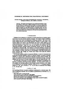
The aim of this section is to show the sparsity pattern and the comparison of standard state space form and it’s descriptor form of the models that are introduced in the above Sections. Figure 3.1 shows a power system model from [20]. Figure 3.1a shows the sparsity pattern of the unreduced Jacobian matrix A when the model is put as a descriptor form in (3.10) where the dimension of this matrix is 7135. When this model is put into standard state space form (3.9), the dimension of J (Figure 3.1b) is only 606, but the number of non-zero elements is larger than that of the descriptor form. Figure 3.2 presents the sparsity pattern of the piezo-mechanical model considered from [34]. Figure 3.2a, Figure 3.2b and Figure 3.2c are showing the sparsity pattern of the mass, damping and stiffness matrices respectively in (3.11). Figure 3.2d and " Figure # 3.2e are showing the sparsity Ja Jb pattern of the matrices E1 and A = , respectively when the model is Jc Jd represented in descriptor form (3.15). Figure 3.2f shows the sparsity pattern of the matrix J = (Ja − Jb Jd−1 Jc ) of the state space form of the piezo-mechanical model in (3.16). From Figure 3.2d and Figure 3.2e one can easily identify that dealing with the representation of the piezo-mechanical model in (3.15) is convenient in the MOR algorithms.
(a) System matrix A in (3.10)
(b) System matrix J in (3.9)
Figure 3.1: Sparsity patterns of the power system model (data source: [20])
3.4. Graphical representation of the system matrices
(a) Mass matrix M
(b) Damping matrix D
(c) Stiffness matrix K
(d) Matrix E1
(e) Matrix A
(f) Matrix J
29
Figure 3.2: Sparsity patterns of the piezo-mechanical model (data source: [34])
30
Chapter 3. Introduction to model problems
CHAPTER
FOUR
GENERALIZED SPARSE LRCF-ADI METHODS FOR SOLVING LYAPUNOV EQUATIONS OF LARGE SPARSE SYSTEMS
It is well known that the most expensive part in approximating a large system via balanced truncation is the solution of two Lyapunov equations for the controllability Gramian and observability Gramian. Many books, journals and research papers introduce numerous techniques or methods to solve Lyaponuv equations exactly as well as approximately. Among these methods, Bartels-Stewart methods [6], Hammarling methods [32], Krylov subspace methods [39], ADI methods [67], low rank iterative methods [62], and later low rank Cholesky factor ADI methods [47, 39, 7] that have been developed over the last decades are remarkable. But in real life, problems are not confined with a particular size or structured indeed. As the methods become more efficient, the size of the feasible and the desired problems grow. As a result research is still going on in developing more and more efficient techniques. This chapter studies one such method; sparse low rank Cholesky factor ADI introduced in [20] and this idea is extended to the generalized case. The first section gives a brief overview of past work on ADI methods. GSLRCF-ADI (generalized sparse low rank Cholesky factor ADI) algorithm is discussed in the second section. Finally the third section contains some numerical results.
Chapter 4. Generalized sparse LRCF-ADI methods
32
4.1
A brief review of ADI methods
For convenience, let us recall the following LTI continuous-time system ˙ = Jx(t) + Bu(t), E1 x(t) y(t) = Cx(t) + Da u(t),
x(t0 ) = x0 ,
(4.1)
where E1 is a nonsingular matrix, J = (Ja − Jb Jd−1 Jc ), B = B1 − Jb Jd−1 B2 , C = C1 − C2 Jd−1 Jc and Da = −C2 Jd−1 B2 . The sub-matrices Ja , Jb , Jc , Jd , B1 , B2 , C1 , C2 are defined in the earlier chapter. x(t) ∈ Rn , u(t) ∈ Rp , and y(t) ∈ Rm are state, input and output vectors, respectively. When E1 = I (identity matrix), clearly (4.1) is a standard state space system. However one can write (4.1) as a descriptor form: # #" " # Ja Jb x(t) B + 1 u(t), Jc Jd ϕ(t) B2 | {z } |{z} F A " # h i x(t) y(t) = C1 C2 . | {z } ϕ(t)
" #" # ˙ E1 0 x(t) = ˙ 0 0 ϕ(t) | {z } E
"
(4.2)
L
If the system in (4.1) is stable, the controllability Gramian Wc ∈ Rn×n and the observability Gramian Wo ∈ Rn×n are the unique solutions of the following pair of continuous-time algebraic Lyapunov equations (CALE) [31]: • standard case (when E1 = I): JWc + Wc JT = −BBT
[controllability CALE],
(4.3a)
JT Wo + Wo J = −CT C [observability CALE],
(4.3b)
• generalized case: JWc ET1 + E1 Wc JT = −BBT
[controllability CALE],
(4.4a)
JT Wo E1 + ET1 Wo J = −CT C
[observability CALE].
(4.4b)
Note that controllability Lyapunov equations and observability Lyapunov equations are dual of each other. Therefore, we emphasize on the controllability Lyapunov equations through out the chapter.
4.1. A brief review of ADI methods
33
The ADI iteration was first introduced by the authors in [46] to solve parabolic and elliptic difference equations. In general formulation, consider a linear system of the form (H + V)y = b,
(4.5)
where b is an n−dimensional vector. The matrices H and V are commuting, positive definite and symmetric. H may be represented as the discretization in x−direction, whereas V may be represented as the discretization in y−direction. Usually, the ADI method is proceeding in two stages. At first a half-step is to take in the direction H implicitly and in the direction V explicitly, then a half-step is to take in the direction V implicitly and in the direction H explicitly. Now applying this idea to the general problem (4.5) the equations for the ADI method can be written as: (H + µ j I)y j− 1 = (µ j I − V)y j−1 + b, 2 (V + µ j I)y j = (µ j I − H)y j− 1 + b,
(4.6)
2
where µ1 , µ2 , · · · are called ADI shift parameters. Author in [67] shows that, one can considers (4.3a) as a ADI model problem, and the (approximate) solution of Wc can be obtained by following iterations [31]: i− 21
(J + µi I)Wc
= −BBT − Wic (JT − µi I),
(4.7a)
i− 1
(J + µi I)(Wic )∗ = −BBT − (Wc 2 )∗ (JT − µi I),
(4.7b)
where W0c = 0, and ADI shift parameters P = {µ1 , µ2 , · · · } ⊆ C− (open left half complex plane). Combining (4.7a) and (4.7b), one can find the following single equation: Wic =(J − µ∗i I)(J + µi I)−1 Wci−1 [(J − µ∗i I)(J + µi I)−1 ]∗ − 2ρi (J + µi I)−1 BBT (J + µi I)−∗ ,
(4.8)
Q (J−µ∗ I) where ρi = real(µi ). The spectral radius of the matrix li=1 (J+µii I) , denoted by ρsr , determines the rate of ADI convergence, where l is the number of shifts used [31]. Note that since the matrix J is asymptotically stable, ρsr < 1 [31]. Smaller ρsr guarantees faster convergence [20]. The minimization of ρrs with respect to shift parameters µi is called the ADI mini-max problem [47]: {µ1 , · · · , µl } = arg
min
max
µ1 ,µ2 ,··· ,µl λ∈Λ(J)
l Y | µi − λ | i=1
| µi + λ |
,
(4.9)
which gives the idea to generate the optimal and suboptimal ADI parameters. Here, Λ(J) denotes the spectrum of J. One can use single shift
Chapter 4. Generalized sparse LRCF-ADI methods
34
(µi = µ; i = 1, 2, · · · l) throughout the ADI iteration. Then the ADI iteration reduces to the Smith method which can be summarized as follows [31] Wkcs
= −2µ
k−1 X
j
j
Jµ Bµ BTµ (Jµ )T ,
(4.10)
j=0
where Jµ = (J − µI)(J + µI)−1 , Bµ = (J + µI)−1 B. However, later Penzl showed in [47], although Smith method is convenient in using single shift, the rate of convergence is not up to mark. And he proposed that instead of a single shift, if l number of shifts are used, then the ADI convergence rate is faster. He also added that if one uses more shifts than l the rate of convergence is not improved further (see [47] for more details). Penzl introduces a set of l suboptimal shift parameters which can be chosen by a heuristic procedure that will be discussed later.
LRCF-ADI iterations:
If we assume that (BBT ) in (4.3a) has lower rank (r) compared to the order of the system (n) (r ≤ p