Available online at www.sciencedirect.com Available online at www.sciencedirect.com
Procedia Engineering
ProcediaProcedia Engineering 00 (2011) Engineering 29 000–000 (2012) 3227 – 3233 www.elsevier.com/locate/procedia
2012 International Workshop on Information and Electronics Engineering (IWIEE)
Numerical Simulation and Experiment Study on Efficiency of Inertia Separator Li Hong-weia,b*, Liu Jing-jiangb, Liu Jingb, Han Hai-bob, Niu Lib a
School of Astronautic Science and Engineering, Beijing University of Aeronautics and Astronautics, Beijing 100191,China b Baicheng Ordance Test Center of China, Baicheng 137001, China
Abstract The concentration precision of the sand/dust test and the attrition of key parts are affected seriously by the inertia efficiency separator, so the study on the separator performance is needed in the design of the sand/dust test system. With the application of discrete phase model,the performances of the manifold inertia separation components are simulated in various air velocities. The trajectories of motion of the particles in the separator are obtained, and the main factors which affect the separation efficiency are analyzed separately. According to the numerical simulation results, three types of separation components are designed and used in the experiment study, the results of the experiment study and the numerical simulation are consistent. The study results indicated that the increase of the particle dynamic energy is the main cause which leads to the separation efficiency drop rapidly while the air velocity increases. The efficiency of the slab-sided separation component with a semicircle bottom is higher than the traditional square short component and affected by the air velocity slightly, so this kind of separation component is adapted to be used in the sand/dust test system where air velocity varies in an extensive range.
© 2011 Published by Elsevier Ltd. Selection and/or peer-review under responsibility of Harbin University of Science and Technology Open access under CC BY-NC-ND license. Keywords: Hydromechanics; U figure inertia separator; gas/solid two-phase flow; CFD; environmental test
1. Introduction Sand/dust environment has a serious destructive effect on the equipments, and it is a major environmental factor,which makes much equipment lose efficacy, so the sand/ dust test methods are
* Corresponding author.: E-mail address:
[email protected]
1877-7058 © 2011 Published by Elsevier Ltd. Open access under CC BY-NC-ND license. doi:10.1016/j.proeng.2012.01.471
23228
Li Hong-wei et al. / Procedia Engineering 29 000–000 (2012) 3227 – 3233 Author name / Procedia Engineering 00 (2011)
prescribed in many technical standards at home and abroad. For the sand/dust test system, in order to avoid the continuous increase of the sand/dust concentration when the air flow blowing on the materiel, ensure the test precision and decrease adverse effects, for example, the attrition and erosion of the key components such as fan vane caused by sand particles, the particles remain in the air flow must be reclaimed efficiently. Traditional circumfluent impacting inertia separator has the advantages of simple structures,high efficiency and lower resistance, it is widely used in gas solid separation field,for instance, the circular fluidized boiler bed. But the separation efficiencies are affected not only by the air velocity, concentration of the particles, rows of the separation components and the transverse and longitudinal spacings of the components[1,2], but also the shape and structure parameters of the separation components are important factors[3]. For the purpose of getting a satisfied separate efficiency, it’s necessary to study the performance of separator in the large sand/dust test system. 2. Research approaches and the experiment facilities 2.1. The method of numerical simulation 2.1.1. Physical model and the grid generation The cross section of the inertia separator studied in this paper is 1m×1m, and the length is 1.2m along the flowing direction, the separation components are fixed 0.5m apart from the entrance. The width of the components is 40mm, the transverse spacing between neighboring components is 80mm, and the longitudinal spacing is adjusted according to the requirements of the experiment and calculation. Since the region is a regular oblong and matches the characteristics of symmetry, just 1/2 of the inner flow field of separator is numerical simulated to improve the simulation precision and efficiency,and the total amount of grid is about 1~1.3 million. The configurations of the separator and three kind of separation components are shown in Fig.1. The outlet of the separator has been defined as the boundary condition of “escape”, and the bottom of separator has been defined as the boundary condition of “trap”. Count up the number of the trapped particles and the total mount of the injected particles with different radii after calculation. The ratio of the trapped number to the total mount is the separation efficiency of this kind of particles, the total separation efficiency is calculated according to the mass fraction of various particles. 2.1.2. Mathematical model Generally, there are two main methods to study multiphase flow in FLUENT, the Euler-Euler method (two-phase/multi-phase model) and Euler-Lagrange method (particle trajectory model or discrete phase model)[4,5]. The discrete phase model assumes that the second phase (discrete phase) is so sparse that the interactions between the particles can be ignored, and takes no account of the effects of the volume fraction of the particles on the continuous phase,all these assumptions are accordant to the characteristic of the object studied in this paper, so the discrete phase model(DPM) is adopted in calculation. In DPM, the fluid phase is treated as continuum by solving the time-average Navier-Stokes equations under Euler frame. As for the study of the discrete phase (particles), the force balance equations of single particle are solved according to the flow field variable,get its speed and finally track its trajectory. In the flow field,the forces acting on the particles are really complex[1], including the fluid drag force(viscous resistance), the gravity, the pressure gradient force, the additional quality force etc. Among these forces, the gravity and the fluid drag force are main forces acting on particles in the separation process of fluid, other forces are
Li Hong-wei et al./ Procedia / ProcediaEngineering Engineering0029(2011) (2012)000–000 3227 – 3233 Author name
3
much less in magnitude in this study, and are not taken into consideration in calculation. The force balance equation of the particle could be written (for the x direction in Cartesian coordinates) as:
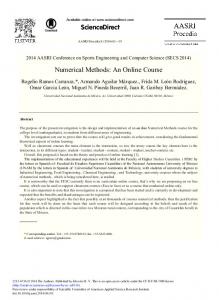
Transverse space
(a)Flat hemline(b)Semicircle hemline(c)Semicircle hemline with lengthened wing (d)Separator and components
Fig.1 Sketch map of three kinds of component and separator
du p
= FD ( u − u p ) +
gx ( ρ p − ρ )
(1) + Fx dt ρp where FD(u-up) is the drag force per unit particle mass, and FD=3 μ CDRe/(4 ρ pdp2) (s-1),u is the velocity of fluid phase(m/s), up is the velocity of the particle(m/s), μis the dynamic viscosity of the fluid(Pa.s)、ρ (kg/m3)is the density of the fluid, ρ p(kg/m3)is the density of the particle, dp(m)is the diameter of the particle, relative Reynolds number Re= ρ dp|up-u|/ μ , drag force coefficient CD=a1+a2/Re+a3/Re,a1、a2、a3 are constant. Fx is an additional acceleration (force per unit particle mass) term. 2.2. Experimental methods and facilities The separator model used in experiment has the same configuration and size with the calculating model described in 2.1.1. The inertia separator is fixed in the test section of the sand/dust test wind tunnel (maximum wind speed is 30m/s, the wind speed and the sand blast can be adjusted continuously), injected sand particles under various air flow velocities, collected the sand particles by a sand collection apparatus from the upper reaches and the lower reaches of separator. Get the separation efficiency by weighting method,alter the configuration and the longitudinal spacing of the components, and finally contrast the effects of components’ configuration and the longitudinal spacing on the separation efficiency. The particle used in experiment is silica sand with a diameter of 220~1000 μm. The design of separator based on the numerical calculation results, the profile of the separate components is shown in Fig.1. (a),(c). The widths of these three components are same. The hemline of component 1# is flat, while 2# and 3# are semicircles with edge folds at the entrance, but are differ in depth along the flow direction. The components are assembled on a shell, so the longitudinal spacing can be adjusted conveniently,and it is easy to compare the influences of various longitudinal spacings on the separation efficiency. Other devices including the sand collection apparatus, portable anemometer (precision is 0.1m/s), electronic balance (precision is 0.1g) etc. 3. Results analysis
3229
43230
Li Hong-wei et al. / Procedia Engineering 29 000–000 (2012) 3227 – 3233 Author name / Procedia Engineering 00 (2011)
100
100
90
90
90
80
70
Experiment Calculation
60
50
80
70
4
5
6
7
8
Air speed/(m/s)
9
10
11
(a)Efficiency of component 1#
Experiment Calculation
60
50
3
Efficiency/(%)
100
Efficiency/(%)
Efficiency/(%)
3.1. The influence of air velocity on separation efficiency
80
70
50 3
4
5
6
7
8
9
10
11
Experiment Calculation
60
3
4
(b)Efficiency of component 2#
5
6
7
8
9
10
11
Air speed/(m/s)
Air speed/(m/s)
(c)Efficiency of component 3#
Fig.2. The separate efficiency curves of three kinds of components under various air speed
(a) Air velocity is 4m/s
(b)Air velocity is 10m/s
Fig.3. The moving trajectories of particles in separate components under various air velocities (the hemline is flat)
The curves of the separation efficiency of three kinds of components under various air velocities are shown in Fig.2. , the data are obtained by numerical calculation and experimental methods respectively. The curves show clearly that the air velocities affect the separation efficiency apparently. The results of the numerical calculation and the test show that once the air velocity becomes higher,the efficiencies of three kinds of separation components lows in various degree. According to the traditional theoretical analysis, in the inertia separator, the higher air velocity it becomes, the larger kinetic energy of particle it has, the centrifugal force of particles is enlarged accordingly, and the particles are easier to be separated from the air flow. On the other hand, the increase of the air velocity means that the drag force acting on the particle is increased; the particles are easier to be entrained by air flow. The general trend of the influence of the air velocity on the separation efficiency is determined by these two effects. Fig.3. reveals the particles’ trajectory of motion , which is obtained by numerical simulation, the hemline of the component is flat, the color of the trajectories represent the particles’ speed. It’s clearly that, when the air velocity is slow, the reverse motion distance of particles is relatively short,and only a few of particles are secondarily entrained by air flow,however,when the air velocity increase, the reverse motion distance of particles increase rapidly, and the secondary entrainment increases obviously. Thus it is clear that the effect of the enlarged particles kinetic energy should be subdivided into two aspects. On one hand, it is easier to make the particles escape from the main air flow and enter the inner of the components, and it is advantageous to improve the separation efficiency; on the other hand, it increases the speed of
Li Hong-wei et al./ Procedia / ProcediaEngineering Engineering0029(2011) (2012)000–000 3227 – 3233 Author name
5
rebound when the particles are in collision with the inner wall of the components, once the speed reaches a certain magnitude, it makes the particles escape from the separation components,bring them back to the main air flow and finally escape by secondary entrainment of the main air flow.
100
100
90
90
90
80
70
80mm 100mm 120mm
60
50
3
4
5
6
7
8
9
Air speed/(m/s)
(a)Efficiency of component 1#
10
Efficiency/(%)
100
Efficiency/(%)
Efficiency/(%)
3.2. The influence of longitudinal spacing between neighbor components on separation efficiency
80
70
80mm 100mm 120mm
60
50
80
70
50
3
4
5
6
7
Air speed/(m/s)
8
9
(b)Efficiency of component 2#
10
120mm 140mm 160mm
60
3
4
5
6
7
Air speed/(m/s)
8
9
10
(c)Efficiency of component 3#
Fig.4. The separate efficiency curves of three kinds of component under various longitudinal space
The longitudinal spacing is defined as the distance between entrances of proximate components along the flow direction, as shown in Fig.1. The experimental results indicate that, the longitudinal spacing affects the separate efficiency greatly, but the mechanism is really complicated, it is not only related with the air velocity, but also has contact with the configuration and the geometry parameters. The separation efficiency curves of three kinds of components under various longitudinal spacings are shown in Fig.4., the data are obtained by experimental method, and the air velocity increases from 3.3m/s to 9.7m/s. It’s clearly that, there is an optimal longitudinal spacing in various experiment conditions. When the longitudinal spacing increases,the area of the air flow passageway between two rows of components along the air flow direction is larger, the average velocity of the local air flow decreases, and the replicate angle becomes smaller. The reduction of the average local speed means the ability carrying the sand is weaken , and it’s advantageous to improve the gas-particle separation , however , when the angle becomes smaller,particles are not easy to escape from the main flow, and this is disadvantageous to the gas-particle separation, so the influence of the longitudinal spacing on the separation efficiency needs to be analyzed comprehensively. When the longitudinal spacing reaches the top, with the increase of air velocity, the average air velocity is lower comparatively, the advantage of lower drag force appears gradually, accordingly, though the separation efficiency also trends to decrease, but the downtrend is gentle. For the component 1# and 2#, which depth is small comparatively, once the air velocity is beyond a certain value, the optimal efficiency can be obtained under the maximum longitudinal spacings, as shown in Fig.4 (a) and (b). As shown in Fig.4 (c), however, generally for the component 3#, the separation efficiencies under various longitudinal spacings are higher than 2# and 3#, and the changes are also mildly. It indicates that the enhancement of depth improves component’s adaptability to air velocity, and this kind of component is appropriate to be used in conditions where the speed of air flow containing sand/dust particles varies within a large range. 3.3. The influence of component’s configuration parameters on separation efficiency The efficiency comparison of three kinds of components under minimum longitudinal spacing is shown in Fig.5., the date are obtained by experimental method, and particles’ trajectories of motion in
3231
63232
Li Hong-wei et al. / Procedia Engineering 29 000–000 (2012) 3227 – 3233 Author name / Procedia Engineering 00 (2011) 100
Efficiency/(%)
90
80
70
1# 2# 3#
60
50
3
4
5
6
7
8
9
10
Air speed/(m/s)
Fig.5. The influence of component’s configuration parameter on separate efficiency
(a) Component 1#
(b)Component 2#
Fig.6. The moving trajectories of particles in the inner of components
components obtained by numerical method are shown in Fig.6. From the experimental data it is clear that when the air speed is lower relatively, the efficiencies of 1# and 2# are close, as the air velocity increases, the difference of rebound appear gradually, when the air velocity is 9.7m/s, the dispersion is 5.2%. In Fig.6, it shows that the particles’ trajectories of motion are more complicated since the effect of semicircle hemline, the increase of the impact among particles and components aggravate the wastage of particles’ kinetic energy, by this way, improve the separation efficiency under higher air velocity. As for the component 3#, its efficiency is higher than 1# and 2# apparently under various air velocities, besides the influence of the semicircle hemline, the increase of depth make it more difficult for the particles to escape from the components, and maintain the higher separate efficiency under various air velocities thereby. 4. Conclusion The DPM of the software Fluent is adopted to conduct a numerical simulation on the separator efficiency of various separation components, forecast the trend of the separator efficiency preferably, and then gains the separator efficiencies of various separation components under the different operation conditions via experiments. The result of the study indicates that: First point: Air velocity is one of the key factors that affect the separator efficiency heavily. It is found that the increase of the air velocity is advantageous for the particles to escape from air by the analysis on how air velocity exerts an influence on the separator efficiency, however, once the depth of separation elements is not large enough , the excessively high energy of motion leads to such a result that a great number of particles reenter the major region as a result of their quick rebound after the crash with the separation components, then escape from the separator due to the second entrainment of the air velocity, which is one of the significant causes leading to the sharp decrease of the separator efficiency at a high air velocity. This discovery provides a new way of thinking for the design of efficient separator.
Li Hong-wei et al./ Procedia / ProcediaEngineering Engineering0029(2011) (2012)000–000 3227 – 3233 Author name
Second point: The alteration of the shape of the separation components' hemline conducts a remarkable influence on the moving trajectories of solid particles in the components, and the consumption of the kinetic energy of the particles can be increased effectively to improve the separator efficiency effectively by the optimal design of the shape of the hemline. Third point: The efficiency of the inertial separator is determined by the synthetic effect of various factors, the influence of which should be analyzed under the certain conditions. Previous studies have indicated that the separator efficiency will peak when the longitudinal spacing is 2-2.5 times as abroad as the separation component, while this paper demonstrates that the separator with larger longitudinal space is more flexible to the air velocity. Although the efficiency is not always being the lowest one when air velocity is low, it declines gently with the gradual increase of the air velocity, and gets the highest efficiency under the certain circumstances. Fourth point: The semicircular separation component designed by the numerical simulation results is slab-sided and high-efficient, and the efficiency doesn't decline apparently along with the increase of the air velocity. It is suitable for the occasions where the air velocity varies greatly and the occasions with high requirement for separator efficiency. References [1]Cen Kefa etc. The Theories and Technologies of Gas-Solid Separation. Hangzhou: Zhejiang University Press; 1999,p.78, p.278 [2]Akira Ogawa. Separation of Particles from Air and Gases. Florida: CRC Press; 1984:2. [3]Tan Xiaojun, Chen Lihua, Li Hongjian, Numecical Simulation of Gas-solid two-phase Flow in Semiround-pipe Inertia Separator. Journal of Hydrodynamics 2005; Ser, A, Vol.20, Supp [4] Jiang Fan etc. The Advanced Application and Example Analyze of Fluent. Beijing: Tsinghua University Press; 2008, p140183 [5] “Equations of Motion for Particles”, FLUENT 6.3 User’s Guide, Segment 2, Chapter 22. [6] Yan Chao. The Methods and Application of Computational Fluid Dynamics. Beijing: Beihang University Press; 2006, p1014
7
3233