Available online at www.sciencedirect.com
Physics Procedia 33 (2012) 1833 – 1841
2012 International Conference on Medical Physics and Biomedical Engineering
Numerical Simulation on the Spontaneous Ignition of Leaking High Pressure Hydrogen from Terminal Unit Shen Xiaobo, Sun Jinhua State Key Laboratory of Fire Science University of Science and Technology of China Hefei, China
[email protected]
Abstract The CFD simulation study was carried out on the spontaneous ignition of high pressure leaking hydrogen from some terminal units. An integrated 2D axisymmetric PDF numerical model was established. The results show that, the strong and weak discontinuous surfaces accompanied by combustion phenomenon are formed leading the local temperature and density rising up sharply. Near the outer-edge of the tube mouth, the vortexes are prone to take shape, which contribute to the mixing of hydrogen and air resulting in intenser and longer time combustion. But the combustion is not sustainable and will die out finally. The simulation catches the detailed jet structure including mach disk and barrel shock.
2011 Published by Elsevier Ltd. Selection and/or peer-review under responsibility of [name Committee. organizer] ©©2012 Published by Elsevier B.V. Selection and/or peer review under responsibility of ICMPBE International Open access under CC BY-NC-ND license. Keywords- terminal unit; CFD; spontaneous ignition; jet structure
1 Introduction As the increasing exhausting of fossil fuel, development of some new energy comes to be the right way to solve the problem. Hydrogen is regarded as a sustainable and environmentally friendly green energy. In US and European, hydrogen energy has been widely used. But compared to the spread of hydrogen energy, the corresponding safety technologies lag behind [1]. Now, the main storage methods of hydrogen include high-pressure storage, liquid storage, metal hydride, carbon material storage and chemical storage and so on. Sarkar [2] proposed that high-pressure hydrogen storage is the most economical and proper choice from the sight of energy analysis. But due to the flammable,
1875-3892 © 2012 Published by Elsevier B.V. Selection and/or peer review under responsibility of ICMPBE International Committee. Open access under CC BY-NC-ND license. doi:10.1016/j.phpro.2012.05.292
1834
Shen Xiaobo and Sun Jinhua / Physics Procedia 33 (2012) 1833 – 1841
explosive and high diffusive properties, it is easier for hydrogen to cause serious fire or explosion accidents. A survey about hydrogen accidents conducted by developed countries in US and European indicates that the causes of 59.98 % of total cases have not been identified and no apparent ignition sources are found. Wolanski and Wojciki [3] first proposed the diffusion ignition mechanism of high pressure hydrogen. When the hydrogen leaks from the high pressure storage tank, a shock wave would be formed and heat the air ahead to an elevated temperature. Once the cold hydrogen mixes with the hot air and approaches the ignition condition, combustion or explosion would occur. Namely, the hydrogen/air mixture would be ignited at normal initial temperature. In recent years, lots of experiments and numerical simulations have been carried out. But under the confinement of high danger and test method, experiments could only qualitatively catch the impact of the initial temperature and pressure, leaking orifice diameter and shape, duct length and diameter on hydrogen spontaneous ignition process. However, the numerical simulations overcome some shortcomings of the experiments. The detail analyses are possible for shock wave formation, development and reflection in the tube, the pressure, temperature and species concentration distribution, and the refine jet structure. Nevertheless, most of those simulations were executed in codes with different discrete schemes, turbulence models, reaction mechanisms and thermal properties with limited validation and application. And also the codes occupy great computing source which is not available for general engineers. When the high pressure hydrogen leaks, the shock wave could heat the air to the spontaneous ignition temperature 843K or more. So the spontaneous ignition is dominated by mixing. In our paper, the detailed chemical reaction mechanism is not considered and the “worst case” assumption, namely, the “fast chemical reaction” assumption is adopted. The combustion occurs once the mixture is formed. The PDF model in Fluent CFD software is utilized for numerical simulation of specific high pressure hydrogen leakage problem. The total process is observed and analyzed for deep insight of the formation and development of hydrogen spontaneous ignition. 2 Problem description and numerical method Hydrogen fuel cell is treated as one of the most promising hydrogen energy applications. The matched fundamental installations, such as hydrogen refueling station, should also be constructed [13-14]. The storage pressure in the stations reach 40-45MPa in our country, and corresponding vehicle mounted gas cylinder is operated at 35MPa. Now, as the development of manufacturing process of storage tank, the 700bar tank is about to come into use. The intrinsic safety of storage tank is continuously increasing and the accidents resulted from the direct leakage from the tank is effectively controlled. And a great part of those accidents originate from high pressure hydrogen terminal unit which is operated at lower pressure than storage tank. For example, the hydrogen gas cylinders (40L) with 15MPa storage pressure are common in factories and laboratories. The output pressure from the cylinder reducing valve is about 2.5MPa. When the hydrogen is transported through pipelines to working stations, the leakage is more probable and could result in fire and explosion. Thus, 3MPa is taken as the characteristic pressure in terminal unit. A 2D axisymmetric model for spontaneous ignition is built. And only the upper half of the model is calculated for efficiency. As shown in Fig.1, the diameter of the tube is 2mm with 5mm length. The total computing district is 15mm 10mm.
Shen Xiaobo and Sun Jinhua / Physics Procedia 33 (2012) 1833 – 1841
Figure 1. Problem description
Pc
According to the choked flow theory [10] the static pressure of the leakage orifice could calculated by P0 [2 / k 1]k / k 1 . The gas is treated ideally and adiabatic exponent k 1.4 , i.e. Pc 0.528 P0 P0 is
the total pressure . The computing district is filled with quadrilateral structured meshes. And the mesh selfadaption technique is used for dealing with the complexity of the problem: small convective and diffusive scales and supersonic flow. The mesh would be condensed in zone with high pressure gradient for refinement and convergence of solving process and capturing detailed shock wave structure. At the end of this simulation, the mean mesh size decreases to 10 m High speed jet outside the tube mouth is formed due to high pressure in the equipment and pipelines. So the SST k turbulence model is used, which considers both the refinement and robustness near the wall (k model) and the independence of free flow in the far field ( k model). That is, different equations will be activated in different regions. The model is applicable for wall restriction flow and free shear flow. Thermochemistry calculation is conducted in prePDF. According to the reaction mechanism, nine species H2 H O O2 OH H2O H2O2 N2 HO2 exist in the combustion system. Chemical reaction is equilibrium and non-adiabatic. The calculation results are tabled for lookup by Fluent. The time step is 1 10 9 s 3Results and discussion
3.1 Parameter analysis in tube mouth 3.1.1 Pressure and density curve on the symmetric axis Fig.2 shows the pressure and density curves at 4 s and 12 s (the zero point on the x-axis indicates the joint of the tube and the terminal unit, i.e. pressure inlet). The high pressure hydrogen leaks abruptly from terminal unit into the tube forming a jet outside. The static air must be strongly compressed and create a pressure discontinuity which is distinguished at x=0.006 m. At the same time, density rises rapidly with a density discontinuity. In the early stage of escape from tube, at about 4 s , the pressure and density goes up 1mm away from the tube mouth compared to those inside the tube. It could be explained that, the high pressure hydrogen counteracts with surrounding air drastically and the second compression makes the interface condensed further. But the hydrogen escaping from the tube would strongly expand specially near the outer side of the tube mouth. The expansion wave could lead to the decreasing of pressure and density which is compensated by the following high pressure hydrogen. So the pressure around the tube mouth and inside the tube fluctuates with a constant statistically mean value (Fig.2, left). Furthermore, at 4 s and 12 s , the discontinuity stabilizes at about x=0.006 m, which is resulted from
1835
1836
Shen Xiaobo and Sun Jinhua / Physics Procedia 33 (2012) 1833 – 1841
the interaction of compression and expansion wave. That is, at x=0.006 m, the pulsation of high pressure hydrogen make the discontinuity shake on the x-axis. At 12 s , there is a weak discontinuity at x=0.014 m for both pressure and density. This is due to the separation of shock wave and discontinuity and downward propagating of the shock wave. But the shock wave interacting with air continuously decays without energy supplement. pressure loss is about 7.5 105 Pa during 6 s to 12 s
5x10
6
4x10
6
3x10
6
2x10
6
1x10
6
8
/Pa
7 6 5 4
3
2
/(kg/m )
3
1 0 0.000
0.003
0.006
0.009
0.012
0 0.015
/Pa
/m
6
5
3x10
6
4
2x10
6
3
1x10
6
2
3
/(kg/m )
4x10
1 0 0.000
0.003
0.006
0.009
0.012
0 0.015
/m
Figure 2. The pressure and density curves near the tube mouth (4
s left and 12
3.1.2 Temperature on the symmetric axis Fig.3 shows the temperature curves at 4 s and 12 s on the symmetric axis.
s right)
Shen Xiaobo and Sun Jinhua / Physics Procedia 33 (2012) 1833 – 1841
1800
/k
1500
4 1
1200 900 600 300 0.000
0.005
0.010
0.015
/m
Figure 3. The temperature curve near the tube mouth at different times
At 4 s , corresponding to the early stage of hydrogen escape from the tube, the hydrogen is compressed by surrounding air and temperature rise up rapidly just at x=0.006m. But at 12 s , the temperature at x=0.006m is only 300K, which indicate that although the compression effect exists, the cold hydrogen escaping from the tube and the expansion effect cool down the discontinuity more intensely. The temperature rise is not obvious. At 12 s , the temperature peak lies at x=0.012m, close to the weak discontinuity (x=0.014m), which is the result of shock wave. The peak temperature at 4 s and 12 s is 1654K and 948K respectively, which both exceed the spontaneous ignition temperature 843K. It could be supposed that combustion process occurs at corresponding positions. It is worth noting that, the temperature and pressure changes should be correlated with chemical reactions due to the introduction of PDF model, which would be discussed below.
3.2 OH radical contours prePDF need not detailed reaction mechanism but the input of species in the combustion systems [14]. The concentration of some free radicals could be treated as the measurement of chemical reaction rate or the indicator of reaction position. OH radical is chosen to indicate the flame front position in the numerical simulation. Fig.4 shows the OH distribution at different times. The unit of x-axis is meter. At 4 s , the OH radical is distributed widely near the discontinuity at x=0.006m with low concentration indicating the flame front is broad and the combustion is weak. In that place, the high pressure hydrogen counteracts with the air strongly and the temperature rises due to the compression effect. And the interface is too thin that hydrogen and air could only mix by molecular diffusivity slowly. Moreover, at 4 s , the main contribution to the peak temperature 1645K is compression, not chemical reaction.
1837
1838
Shen Xiaobo and Sun Jinhua / Physics Procedia 33 (2012) 1833 – 1841
4 s
6 s
8 s
12 s Figure 4. The OH contours at different times
At 4 s and 12 s , on the axis, due to the strong compression effect, cooling effect and relative weak expansion effect, the pressure decays slowly making insufficient mixing and final quenching of flame. But in the radial direction, due to the strong expansion effect together with the radial diffusivity from the flame front, pressure decreases fast facilitating the mixing process and keeping the combustion longer. Furthermore, OH concentration is rather high near the outer side of tube mouth. It could be explained that, when the hydrogen escapes from the tube and expands freely, the strongest adverse pressure gradient near the outer side of the tube mouth creates a vortex which benefits the mixing of hydrogen and air resulting in a more drastic combustion, as shown in Fig.5. As the time goes on, the continuous leaking hydrogen makes the vortex grow up and the high OH concentration region moves left. But owing to expansion effect and cooling effect, the OH concentration deceases gradually. Based on above analysis, it is concluded that, when the high pressure hydrogen leaks from a tube connected to the terminal unit, due to the expansion effect and cooling effect, the combustion could not sustain and finally goes out. But the instant high temperature regions are possibly the causes for other serious
Shen Xiaobo and Sun Jinhua / Physics Procedia 33 (2012) 1833 – 1841
fire and explosion accidents.
Figure 5. The vortex near the outer-edge of the tube mouth
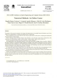
3.3 Mach number contours at different times Mach number contours make a comprehensive view of flow field structure and change pattern near the tube mouth, as shown in Fig.6. When the high pressure hydrogen leaks, the front static air would be compressed first forming a leading planar shock wave which decays into a semispherical shock wave due to the lateral diffusivity and continues to be attenuated by expansion wave. At the same time, the following hydrogen flow reaches the tube mouth and expands strongly forming a semispherical shock wave which is intensified to be a mach disk. When the hydrogen escapes from the tube, the strong expansion waves (red region) are formed, then downward propagate and finally reflect from the pressure boundary (compression wave). All those boundaries construct a barrel shock surrounding the supersonic region behind the mach disk. The flow between the flow boundary and barrel shock is sill supersonic but much slower than that in the barrel shock [9-10].
1839
1840
Shen Xiaobo and Sun Jinhua / Physics Procedia 33 (2012) 1833 – 1841
Figure 6. The mach number contours at different times
4 Conclusions This paper conducted a numerical simulation for spontaneous ignition of high pressure hydrogen leaking from terminal unit based on CFD code. The PDF method was introduced to build a complete 2D axisymmetric model in Fluent. The detailed analyses of parameter distribution, OH contours and jet structures were carried out. (1) When the high pressure hydrogen leaks, a strong discontinuity and a downward propagating weak discontinuity would be formed and both result in local pressure and temperature rise accompanied by chemical reaction. (2) Near the outer side of the tube mouth, due to the strong expansion and adverse pressure gradient, a vortex is easily formed facilitating the mixing of hydrogen and air and makes the combustion intenser and longer. (3) Due to the expansion and cooling effect, the combustion could not sustain. But the instant high temperature regions are possible the causes of some other fire and explosion accidents. (4) CFD simulation captures the detailed jet structures including mach disk and barrel shock for high pressure hydrogen leakage from the tube. Acknowledgement This work has been funded by the National Natural Science Foundation of China (No.50976110). The authors gratefully acknowledge this support. References [1]
G. Astbury. A review of the properties and hazards of some alternative fuels[J]. Process Safety and Environmental
Protection. 2008, 86(6): 397-414. [2]
S. Arindam, B. Rangan. Net energy analysis of hydrogen storage opotions[J]. International Journal of Hydrogen
Energy,2005,30(8):867-877. [3]
G. Astbury, S. Hawksworth. Spontaneous ignition of hydrogen leaks: A review of postulated mechanisms[J].
International Journal of Hydrogen Energy. 2007, 32(13): 2178-2185. [4]
P. Wolanski, S. Wojcicki. Investigation into the mechanism of the diffusion ignition of a combustible gas flowing into an
oxidizing atmosphere[C]//Proceedings of 14th Symposium on Combustion. Pittsburgh: the Combustion Institute,1973:1217-1223. [5]
V.V. Golub, D.I. Baklanov, T.V. Bazhenova et al. Experimental and numerical investigation of hydrogen gas auto-
ignition[J]. International Journal of Hydrogen Energy. 2009, 34(14): 5946-5953. [6]
V. Golub, D. Baklanov, T. Bazhenova et al. Shock-induced ignition of hydrogen gas during accidental or technical
opening of high-pressure tanks[J]. Journal of Loss Prevention in the Process Industries. 2007, 20(4-6): 439-446. [7]
T. Mogi, Y. Wada, Y. Ogata et al. Self-ignition and flame propagation of high-pressure hydrogen jet during sudden
discharge from a pipe[J]. International Journal of Hydrogen Energy. 2009, 34(14): 5810-5816. [8]
F. Dryer, M. Chaos, Z. Zhao et al. Spontaneous Ignition of Pressurized Releases of Hydrogen and Natural Gas into Air[J].
Shen Xiaobo and Sun Jinhua / Physics Procedia 33 (2012) 1833 – 1841 Combustion Science and Technology. 2007, 179(4): 663-694. [9] B.P. Xu, L. Elhima, J. Wen et al. Numerical study on the spontaneous ignition of pressurized hydrogen release through a tube into air[J]. Journal of Loss Prevention in the Process Industries. 2008, 21(2): 205-213. [10] B.P. Xu, J. Wen, S. Dembele et al. The effect of pressure boundary rupture rate on spontaneous ignition of pressurized hydrogen release[J]. Journal of Loss Prevention in the Process Industries. 2009, 22(3): 279-287. [11] E. Yamada, S. Watanabe, A.K. Hayashi et al. Numerical analysis on auto-ignition of a high pressure hydrogen jet spouting from a tube[J]. Proceedings of the Combustion Institute. 2009, 32(2): 2363-2369. [12] F. Williams. Detailed and reduced chemistry for hydrogen autoignition[J]. Journal of Loss Prevention in the Process Industries. 2008, 21(2): 131-135. [13] Zheng Chuguang, Zhou Xiangyang. PDF model of turbulent reactive flow[M]. The second edition. Wuhan: HUST Press Co.,Ltd, 2005.(in Chinese) [14] Fluent 6.3 User’s Guide[M]. New Hampshire, Lebanon: Fluent Inc.,2006.
1841