Little, W. A. , "Proceeding of the NBS Cryocooler Conference", Edited by J. E. Zimmeman and T. M. Flynn, NBS Spec. Publ. No. 508, p. 75, April 1978. 2. Yuen ...
AN EXPERIMENTAL STUDY AND NUMERICAL SIMULATION OF TWO-PHASE FLOW OF CRYOGENIC FLUIDS THROUGH MICRO-CHANNEL HEAT EXCHANGER
W. W. Yuen and I. C. Hsu Department of Mechanical Engineering University of California, Santa Barbara Santa Barbara, CA 93106 and Cryogenic Payloads Laboratory Advanced Technology Center Lockheed Martin Missiles & Space Palo Alto, CA 94304-1191
ABSTRACT The design, fabrication, testing and analysis of a microchannel heat exchanger, a key component for a microminiature Joule-Thomson Cryogenic Refrigerator is described. Results show that the heat exchanger can be fabricated efficiently and economically with the existing manufacturing technology. The heat exchanger was tested to be mechanically robust and durable under high pressure operating condition. “Choking” did not occur in the micro-channels of the heat exchanger. The thermal performance is excellent, providing the rapid cooling as designed. A numerical code is developed both to interpret the data and to provide some sensitivity study and assessment on the performance characteristics of the heat exchanger. Furthermore, this code will be utilized as a design tool for optimizing the performance of next generation planar heat exchangers. INTRODUCTION A microminature Joule-Thomson cryogenic refrigerator is a highly compact and efficient refrigerator which has wide range of potential applications in the cooling of laboratory apparatus and low noise electronic devices under cryogenic conditions. The objective of this work is to develop the fundamental understanding of the thermal and mechanical performance characteristics of a planar microchannel heat exchanger, a key component of the refrigerator. In this paper, results of the first-year experimental and analytical studies are presented.
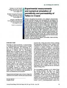
EXPERIMENTS Design and Fabrication of the Heat Exchanger While the need to operate in microminiature size is essential for the success of the refrigerator [1], the exact size of the heat exchanger and the geometric dimension of the microchannel (depth and width) depend on the available fabrication technology. Three microchannel heat exchangers with similar designs were fabricated by the Center for Microelectronics and Optoelectronics of Lawrence Livermore National Laboratory. The dimensions for each heat exchanger unit are 2.54 cm by 3.04 cm and 0.4 cm thick. Each unit is comprised of two halves made of silicon and Corning 7740 borosilicate glass, whose coefficient of thermal expansion closely matches that of silicon. The silicon layer is 1.016 mm thick with multiple micro-channels parallel to the long dimension of the heat exchanger. The first heat exchanger unit has an aspect ratio, between the depth of the micro-channel to its width, of 1.6:1 but the second and third unit have been fabricated with an aspect ratio of 3.4:1; in order to increase the surface area for heat transfer. All of the micro-channels are cut into the silicon layer using a computer controlled dicing saw. The dimensions for the micro-channels in the silicon layer are 813 µm deep and either 508 µm or 239 µm wide, depending on the aspect ratio for the particular unit. All the wall thicknesses for the micro-channels are 102 µm thick. The first heat exchanger unit, with an aspect ratio of 1.6:1, has 36 parallel channels per silicon layer and the other two heat exchangers, with an aspect ratio of 3.4:1, has 65 channels per layer. A schematic of the silicon layer with the micro-channel is shown in Figure 1.
3.04 cm
2.54 cm
Figure 1: Schematic of the silicon layer of the micro-channel heat exchanger.
The borosilicate glass layer is 3.05 mm thick with two flow manifolds of 3.81 mm wide cut into it, parallel to the short dimension of the heat exchanger. The depth of each manifold is 2.03 mm with two circular holes of 3.30 mm diameter bored through the glass layer acting as inlet and exit for the coolant flow. A schematic of the glass layer is shown in Figure 2.
3.04 cm
2.54 cm
Figure 2: Schematic of the borosilicate glass layer. Finally, the finned silicon layer is contact bonded to the glass flow manifold layer to form the complete planar heat exchanger. A photograph of the micro-channel heat exchanger is shown in Figure 3.
Figure 3: A close-up photograph of the micro-channel heat exchanger. Preliminary Test Results To test the mechanical and thermal performance characteristics of the heat exchanger, a series of blow-down experiments have been performed. The heat exchangers are instrumented so that cooling can be achieved and monitored. To enable the high-pressure coolant to flow through the heat exchanger, a stainless steel flat washer was brazed onto one end of a 3.175 mm-OD stainless steel tubing with a 330 µm diameter hole drilled through this washer to act as a Joule-
Thomson expansion orifice. This tubing is then epoxy bonded to the inlet manifold of the planar heat exchanger and supports the heat exchanger inside the test chamber. A rectangular focal plane substrate made of alumina is epoxy bonded to the silicon side of the planar heat exchanger to represent the approximate thermal mass of a planar infrared focal plane assembly. Then a platinum resistance temperature sensor is epoxy mounted onto this alumina substrate and utilized to measure its temperature during Joule-Thomson expansion of coolant flowing through the planar heat exchanger. A schematic of the experimental setup is shown in Figure 4. A photograph of the "instrumented" micro-channel heat exchanger is shown in Figure 5.
Planar HX
Test Chamber
100 cc Gas Tank
Figure 4: Schematic of the blow-down experiment for the micro-channel heat exchanger. Blowdown experiments are performed using krypton compressed to high pressure (170 to 449 bar) with two heat exchangers of different channel width. For a 100 cc volume krypton tank and initial substrate temperature of 288 K (15°C), the minimum temperature achieved for the two heat exchangers with different channel widths are shown in Table 1. Typical temperature transient data for the 504 µm channel-width heat exchanger (at 272 bar) and the 239 µm channelwidth heat exchanger (at 449 bar) are shown in Figures 6.
Table 1: Thermal performance data of the micro-channel heat exchanger. Channel Width = 504 µm Pressure (Bar) Tmin (K) 170 204 204 182 238 176 272 156
Channel Width = 239 µm Pressure (Bar) Tmin (K) 272 180 340 158 374 159 408 151 449 153
Figure 5: Close up photograph of the "instrumented" micro-channel heat exchanger.
Figure 6: Typical temperature transient data for the two micro-channel heat exchangers.
To better compare the thermal performance of the heat exchangers, the flow rate of the coolant through the Joule-Thomson expansion nozzle has to be set to a standard flow rate. Thus second planar heat exchanger with 239 µm channel-width has been retrofitted with a capillary tubing instead of an Joule-Thomson expansion orifice in order to facilitate the adjustment of flow rate. A short length of fine stainless steel hypodermic tubing with an internal diameter of 102 µm was brazed into the 3.175 mm-OD coolant supply line and utilized as a restriction to the flow. The flow rate through this restriction was adjusted to 4.5 standard liters per minute (slpm) of nitrogen by trimming the length of the hypodermic tubing. The nitrogen gas was supplied from a gas bottle with its outlet pressure regulated to 69 bar (1000 psig). Due to a factor of 3.5 reduction in the diameter of the flow restriction, compared with the first heat exchanger unit, the flow rate of krypton through the heat exchanger has been proportionally reduced. This accounts for the slower cooling rate observed for the 239 µm channel-width heat exchanger shown on Figure 6. In all cases, "choking" did not occur in the micro-channels and the heat exchanger remained mechanically stable for all tests. It is interesting to note that both heat exchangers yield approximately the same minimum temperature at the high pressure limit. Additional tests are
currently under consideration to characterize more completely the thermal and mechanical performance characteristics of the heat exchanger ANALYSIS The focus of the analytical effort is to develop a computational capability to perform two phase thermal and flow analysis in arbitrary three-dimensional geometry. The computer code will be used first to analyze performance data of the micro-channel heat exchanger. It will also be the basic design tool used to determine optimal design parameters (e.g. gas mixture ratio, geometric dimensions, etc.) for the microminature Joule-Thomson cryogenic refrigerator. The code is based on a multifield Eulerian treatment [2]. To facilitate the simulation of flows in complex geometry, it assumes three continuous fields (solid, liquid and gas). Complex flow geometry, such as those in a micro-channel heat exchanger, is simulated by specifying a solid fraction distribution in a 3-d flow field. Heat transfer and friction loss boundary conditions can also be simulated with the specification of appropriate solid/liquid and solid/gas interfacial drag and heat transfer constitutive relations. Because of the three-fluid formulation, the code can also be used to simulate the flow of solid particles in liquid/gas two phase mixture. The mathematical formulation is similar to an existing code developed for the analysis of steam explosion [2]. The detail is given in the same reference and will not be repeated here. Due to the relatively large uncertainty in flow conditions associated with the current set of preliminary experiments (for example, the friction loss associated with the various inlet and outlet restriction/orifices are not known), the initial effort of the numerical simulation will focus mainly on the qualitative performance characteristics of the micro-channel heat exchanger. These results are useful to demonstrate the effectiveness of the micro-channel concept and to provide improvements for future designs. Numerical Parameters of the Simulation The flow volume in the micro-channel heat exchanger is modeled by a 28 mm by 22 mm by 3 mm computational domain with a grid size of ∆x = ∆y = ∆z = 1 mm. The silicon layer is modeled as a two-dimensional plane layer within which the fluid is restricted to flow in the ydirection only (the “long (28 mm)” side of the layer). The thickness of the layer is one computational cell, corresponding approximately to the actual depth of the microchannel (813 µm). The flow volume in the channel is preserved by specifying a solid fraction of 0.167 in the layer. The heat transfer across channels is calculated based on fully-developed pipe flow correlations [3]. The two manifolds are modeled as 4 mm wide, 22 mm long and 2 mm deep rectangular volume located on top of the silicon layer. A schematic of the cross-section vertical plane including the inlet from the high pressure tank is shown in Figure 7. Note that this vertical section is closed to the ambient because the venting orifice is located in a different plane. The time step is adjusted automatically by the code to maintain numerical stability. For the results presented in this work (with an inlet pressure of 300 bar), the average time step is 10-8 sec. It is important to note that a direct simulation of all the geometric characteristics of the micro-channel heat exchanger (e.g. taking a grid size of 0.5 mm) is computationally intensive and is probably unnecessary for the current objective of illustrating the qualitative behavior of the heat exchanger. More detailed geometric simulation, together with better characterization of the inlet and outlet friction loss, will be the objective of future calculations.
100 cc High Pressure Tank
Ambient Pressure
3 mm
28 mm
Figure 7: Schematics of the vertical plane including the inlet from the high pressure tank. Results and discussion Numerical results generated for the blowdown of Krypton at a tank pressure of 300 bar is presented. The thermodynamic properties are generated by the program GASPAK[4]. To demonstrate the condensation and flow behavior, the transient void fraction distribution at four different times at the silicon layer is shown in Figure 8. The corresponding distribution in the vertical plane of the inlet orifice in the direction of the microchannel is shown in Figure 9 and the distribution in the vertical plane in the direction of the manifold is shown in Figure 10. The average void fraction in the silicon layer is shown in Figure 11. The void fraction distribution shows clearly that the micro-channel is effective in generating quickly a uniform liquid zone across the full heat transfer surface. The design objective of generating a uniform temperature surface (for example, in infrared detector application) is thus met. The condensation occurs almost instantaneously in the micro-channels near the inlet orifice as demonstrated in Figure 9, and is much less efficient the direction on the manifold, as illustrated in Figure 10. This difference in condensation effect can be attributed to the incompatibility between the inlet flow from a single orifice and the flow direction restricted by the micro-channels. At the channels near the inlet orifice, the stagnation pressure built up locally forces the flow into the micro-channel naturally. The fluid which is directed in the direction of the manifold, on the other hand, must make two 90-degree turns (one downward toward the silicon layer and then sideways into the micro-channel) to enter the micro-channel. This requires significant pressure build-up and thus delays the cooling and condensation of the middle section. This result suggests that the current design can be improved by either by eliminating the microchannel at the area directly under the two manifolds or providing a distributed inlet flow across the inlet manifold. The condensation and cooling can then be achieved more quickly and efficiently. In general, the numerical prediction of temperature and pressure distribution are consistent with experimental data. Discussion of the numerical data, however, is meaningful only if they are presented with a full parametric study on the effect of frictional loss along the orifice. These numerical data are currently being generated and they will be presented in future publications.
Figure 8: Void fraction distribution and liquid volumetric flux at the bottom silicon layer.
Figure 9: Void fraction distribution and liquid volumetric velocity at the vertical plane of the inlet orifice in the direction of the micro-channel.
Figure 10: Void fraction distribution and liquid volumetric velocity at the vertical plane of the inlet orifice in the direction of the manifold.
1.0
0.8
0.6 α avg 0.4
0.2
0.0 0.000
0.005
0.010 Time (s)
Figure 11: Average void fraction at the silicon layer.
0.015
CONCLUSIONS The important basic component of a microminiature Joule-Thomson cryogenic refrigerator, a micro-channel heat exchanger, is designed and fabricated. Preliminary experiments show that the heat exchanger is mechanically robust and has excellent thermal performance characteristics. A computer code is developed both to interpret the performance characteristics of the heat exchanger and to serve as a design tool for the refrigerator. Results of numerical simulation show that the micro-channel heat exchanger is effective in generating a uniform liquid fraction over the whole base surface. Analysis of the predicted flow dynamics suggests a modification in design to improve the condensation efficiency. ACKNOWLEDGMENT This work is supported by Lockheed Martin and the U.C. MICRO program. REFERENCES 1.
Little, W. A. , "Proceeding of the NBS Cryocooler Conference", Edited by J. E. Zimmeman and T. M. Flynn, NBS Spec. Publ. No. 508, p. 75, April 1978.
2.
Yuen, W. W. and Theofanous, T. G., "PM-ALPHA: A Computer Code for Assessing the Premixing in Steam Explosion," DOE/ID-10502, April 1995.
3.
Incropera, F. P. and DeWitt, D. P., "Fundamentals of Heat and Mass Transfer,", 4th Ed., John Wiley and Son, Inc., 1996.
4.
McCarthy, R. D. and Arp, V., "User's Guide to GASPAK, Version 3.1," CRYODATA, P.O.Box 558 Niwot, CO. 80544, 1992.