HIGHWIND, TEMPO and AWESCO projects, since I was able to attend and profit from ...... online: http://cdn.syscop.de/publications/Diehl2016.pdf). [87] Diehl, M.
ARENBERG DOCTORAL SCHOOL Faculty of Engineering Science
Numerical Simulation Methods for Embedded Optimization
Inexact Newton Forward Simulation Iterated Sensitivities
Rien Quirynen Dissertation presented in partial fulfillment of the requirements for the joint degree of Doctor of Engineering Science: Electrical Engineering and Doctor Rerum Naturalium (Freiburg)
January 2017
Numerical Simulation Methods for Embedded Optimization
Rien QUIRYNEN
Examination committee: Prof. Dr. A. Bultheel, chair Prof. Dr. M. Diehl, supervisor (University of Freiburg) Prof. Dr. S. Vandewalle, supervisor Prof. Dr. J. Suykens Ass. Prof. Dr. P. Patrinos Ass. Prof. Dr. G. Pipeleers (all KU Leuven) Prof. Dr. S. Bartels Prof. Dr. D. Kröner (all University of Freiburg) Prof. Dr. Dres. h.c. H. G. Bock (Heidelberg University) January 2017
Dissertation presented in partial fulfillment of the requirements for the joint degree of Doctor of Engineering Science: Electrical Engineering and Doctor Rerum Naturalium Arenberg Doctoral School Faculty of Engineering Science KU Leuven Faculty of Mathematics and Physics University of Freiburg
© 2017 KU Leuven – Faculty of Engineering Science Uitgegeven in eigen beheer, Rien Quirynen, Kasteelpark Arenberg 10 box 2446, B-3001 Leuven (Belgium)
Alle rechten voorbehouden. Niets uit deze uitgave mag worden vermenigvuldigd en/of openbaar gemaakt worden door middel van druk, fotokopie, microfilm, elektronisch of op welke andere wijze ook zonder voorafgaande schriftelijke toestemming van de uitgever. All rights reserved. No part of the publication may be reproduced in any form by print, photoprint, microfilm, electronic or any other means without written permission from the publisher.
Acknowledgements As I believe it should mostly be the case, it is with strongly mixed feelings that I write this final section of my PhD thesis. On the one hand, of course, relief and excitement about what the future still holds. While on the other hand, nostalgia and also astonishment about how fast this period has gone by. I can safely say that the last four years have formed a challenging but mostly exciting journey that allowed me to broaden my horizon on both a personal and professional level. I learned so many new things, experienced new places and this while meeting the most amazing people. For this, I have to thank a lot of people that have contributed to this experience. My first and greatest thanks goes to Moritz Diehl, without whom you would most likely not have been reading my PhD thesis to begin with. He provided me with the initial spark of inspiration and motivation to perform research, starting with my final master project under his supervision. Thanks to his clear passion for research and the very flexible and comfortable working environment that he creates, I discovered my own passion and determination to pursue a PhD. Throughout this experience, Moritz provided me with many more research ideas than one could possibly explore in one PhD project, with the support and flexibility to direct my own research path and the continuous source of enthusiasm and inspiration which makes him such an exceptional supervisor. I also thank Moritz for creating a very fruitful environment for cooperation and exchange of research ideas within the group, which greatly profits from a particular attention to creating an enjoyable working atmosphere. I owe my sincere gratitude to Stefan Vandewalle for his valuable feedback and guidance, and especially for agreeing to become my supervisor at KU Leuven. In addition to my two main supervisors, I would also like to thank Sébastien Gros and Boris Houska, who contributed strongly by mentoring me both on a personal and professional level. Sébastien was a postdoctoral researcher in our group when I started and he helped me with becoming a productive researcher from the very start of my PhD project. But also after he eventually became
i
ii
ACKNOWLEDGEMENTS
assistant professor in Chalmers, we stayed in contact and continued a fruitful cooperation. Similarly, I met Boris as a very bright and inspiring PhD researcher in the same group when I was still a master student myself. I feel privileged to have worked together on a daily basis during my research time in Shanghai and also afterwards, I could always count on his quick but insightful feedback and contributions to joint publications. I would like to thank my colleagues and fellow researchers both in Leuven and Freiburg but also during my visit in Geneva and Shanghai, for the inspiring discussions and collaborations, the relaxing (coffee) breaks and generally the great times we had together in- and outside of the office. From my research period in Leuven, I especially want to thank Adeleh, Andrew, Attila, Boris, Greg, Janick, Joachim, Joel, Joris, Kurt, Mario, Milan, Quoc, Sébastien and Slava. I would like to thank Adrian, Andrea, Dang, Dimitris, Fabian, Gianluca, Gianni, Jochem, Jonas, Jörg, Michael, Mikhail, Rachel, Robin and Thor for creating a fruitful and enjoyable working environment together in Freiburg. Considering the multiple locations where I gained a network of friends and colleagues, it is unlikely that the above lists are close to complete. In addition, I would like to thank both Thiva Albin and Dennis Ritter from the control research group of Dirk Abel at the Aachen University, for our fruitful collaboration resulting in multiple exciting publications. Especially, I would like to express my gratitude to agree on using our algorithms and software for their challenging real-world problem and on their experimental test setup, with the corresponding results in this thesis. I am indebted to Dimitris, Fabian, Rachel, Robin and Thor, as well as both of my supervisors for providing very valuable comments and remarks on earlier versions of this manuscript. I would also like to thank all the members of my PhD jury for reading my thesis and for providing crucial feedback on my research results. I gratefully acknowledge funding by the Research Foundation – Flanders (FWO), through a personal 2 × 2 years PhD fellowship. I would additionally like to thank all people involved at the FWO for their very smooth organization of all administrative tasks, especially considering the multiple locations where I have stayed during my PhD project. Also the funding by the DFG, via the project “Numerical methods for optimization based control of cyclic processes”, as part of the research unit FOR 2401 during the last three months of the PhD is gratefully acknowledged. I would like to thank Leen Cuypers, Jacqueline De bruyn, Elsy Vermoesen and John Vos from KU Leuven and Daniela Högerle, Christine Paasch and Kerstin Pfeiffer from the University of Freiburg for their crucial support with all administrative tasks and for making this joint PhD possible. I also want to thank all people involved in the EMBOCON, SADCO, HIGHWIND, TEMPO and AWESCO projects, since I was able to attend and profit from many of their events with my own funding from FWO. Through
ACKNOWLEDGEMENTS
iii
these various research networks, I met a lot of interesting people with whom I had inspiring interactions and we had great times together. In addition, I gratefully acknowledge the funding from the Junior Mobility Programme (JuMo) in the form of a YouReCa travel grant at the KU Leuven. Within this project on the topic of “Integration Methods for Real-Time Multiple Shooting”, I was able to spend about four months at the University of Geneva and three more months at the Shanghai Jiao Tong University in the period of 2013-2014. I especially thank Martin Gander and Boris Houska for hosting me respectively in Geneva and Shanghai and for providing me with the chances to interact and have interesting discussions with many other researchers. I would additionally like to thank all the amazing people that I met during my time at both locations, in- and outside of the university, since they made my stays such an enjoyable and memorable experience. Last but surely not least, I would like to thank all my friends on whom I could count for support but even more for pleasant distractions from any workaholic tendencies. Especially in the final stage of writing my thesis, many outdoor activities around Freiburg reminded me of the beauty and adventures to be had outside of LATEX. I most definitely cannot imagine this continuing journey without the endless support from my amazing parents, Marleen and Willy, as well as from both of my sisters, Geertrui and Melle.
Rien Quirynen
Abstract Dynamic optimization based control and estimation techniques have gained increasing popularity, because of their ability to treat a wide range of problems and applications. They rely on the explicit formulation of a cost function, which needs to be minimized given the constraints of the problem and the system dynamics. Especially in the context of real-time applications of control and estimation on embedded hardware, the computational burden associated with the online solution of the optimal control problem forms the main limiting factor in the deployment of such an advanced strategy. For that purpose, this thesis considers the development of tailored algorithms of simulation methods for embedded optimization that allows for an efficient implementation of nonlinear model predictive control (NMPC) or moving horizon estimation (MHE). A direct treatment of the optimal control problem requires the numerical simulation of the continuous time nonlinear dynamics and the solution of the resulting large but structured optimization problem. We additionally propose a new format to define the dynamic model, which allows one to directly exploit the present structure of linear or partially linear subsystems in the formulation of the system dynamics. In addition, we also discuss embedded optimization algorithms for a more general set of interconnected subsystems based on a distributed multiple shooting technique. As we focus on Newton-type optimization algorithms, it is important to extend the numerical simulation method with an efficient propagation of its first and possibly higher order derivative information. We discuss the tailored implementation of such a sensitivity analysis for both explicit and implicit integration, such as the collocation methods that form a specific family of implicit Runge-Kutta schemes. In addition, a novel Hessian propagation scheme is proposed for both a discrete and continuous time sensitivity analysis, which allows one to maintain and exploit the symmetry of the second order derivatives. Based on these symmetric sensitivity equations, an alternative three-sweep propagation (TSP) technique is presented and analyzed.
v
vi
ABSTRACT
When embedding an implicit integration scheme within a direct multiple shooting based Newton-type optimization algorithm, one ends up with an outer and inner level of iterations which is typically not the most efficient computational approach. We therefore propose an alternative implementation, which we refer to as a lifted collocation integrator, and discuss its advantages and disadvantages compared to multiple shooting and direct collocation. Two alternative extensions to inexact Newton based optimization are presented, using either an adjoint differentiation technique or an iterative sensitivity propagation. We establish new theoretical results on the local convergence of this inexact Newton scheme with iterated sensitivities. Unlike for previously existing algorithms, we show that local convergence for the inner scheme is necessary and often also sufficient for asymptotic contraction of the new proposed optimization method. In addition to the use of tailored optimal control algorithms, the performance of embedded applications strongly relies on efficient code implementations. This thesis therefore includes an implementation of the major new algorithmic techniques as part of the automatic code generation tool within the opensource ACADO Toolkit software package. We discuss some of the main realworld control applications that were made possible using such an ACADO code generated solver. More specifically, we discuss the airpath control for a two-stage turbocharged gasoline engine in more detail. The resulting NMPC scheme on the dSpace MicroAutoBox is shown to meet the challenging demands of this control application, with a sampling time of 25 ms. It is validated based on closed-loop simulations as well as in-vehicle experimental results.
Beknopte Samenvatting Dynamische optimalisatie gebaseerde controle- en schattingstechnieken worden steeds meer populair, omwille van hun vermogen om een wijde selectie aan problemen en toepassingen te behandelen. Ze zijn afhankelijk van de expliciete formulering van een kostfunctie, welke moet worden geminimaliseerd onder de beperkingen van het probleem en de bijhorende systeemdynamica. Vooral in de context van real-time toepassingen van controle en schatting op ingebedde hardware, vormt de rekenkundige last voor het online oplossen van het optimaal controleprobleem een belangrijke beperkende factor in de implementatie van een dergelijke geavanceerde strategie. Deze thesis beschouwt daarom de ontwikkeling van op maat gemaakte algoritmen voor ingebedde optimalisatie- en simulatiemethoden, welke een efficiënte implementatie toelaten van niet-lineaire model predictieve controle (NMPC) of bewegende horizon schatting (MHE). Een directe behandeling van het optimaal controleprobleem vereist de numerieke simulatie van de niet-lineaire dynamica in continue tijd en de oplossing van het resulterend, groot maar gestructureerd optimalisatieprobleem. We stellen bovendien een nieuwe formulering van het dynamisch model voor, om de aanwezige structuur van (gedeeltelijk) lineaire deelsystemen onmiddellijk te kunnen herkennen en dan ook te benutten. Bovendien bespreken we ook het gebruik van ingebedde optimalisatie algoritmen voor een meer algemene reeks van onderling verbonden deelsystemen, en dit op basis van een gedistribueerde variant van multiple shooting. Gezien we ons richten op Newton gebaseerde optimalisatie algoritmen, is het belangrijk om de numerieke simulatiemethode uit te breiden met een efficiënte propagatie van de bijhorende eerste en hogere orde afgeleiden. We bespreken daarom de aangepaste implementatie van een dergelijke sensitiviteitsanalyse voor zowel expliciete als impliciete integratie, zoals bijvoorbeeld de collocatiemethoden die een specifieke klasse vormen van impliciete Runge-Kutta schema’s. Daarnaast presenteren we ook een nieuw schema voor de specifieke propagatie van de Hessiaan en dit zowel in discrete
vii
viii
BEKNOPTE SAMENVATTING
als in continue tijd. Het laat ons toe om de symmetrie van deze tweede orde afgeleiden te behouden en dan ook te benutten. Op basis van deze symmetrische vergelijkingen, kan een alternatieve three-sweep propagatie (TSP) techniek worden gebruikt voor de sensitiviteitsanalyse. Bij het gebruik van een impliciet integratieschema binnen een Newton gebaseerd optimalisatie algoritme, eindigt men met een buitenste en binnenste niveau van iteraties en dat is typisch niet de meest efficiënte berekeningsaanpak. We stellen daarom een alternatieve implementatie voor, welke we lifted collocatie noemen, en we discussiëren de voor- en nadelen in vergelijking met multiple shooting en directe collocatie. Twee alternatieve uitbreidingen zijn mogelijk voor inexacte Newton gebaseerde optimalisatie, door gebruik van ofwel een achterwaartse differentiatie techniek ofwel een iteratieve sensitiviteitsanalyse. We presenteren nieuwe theoretische resultaten in verband met de lokale convergentie van dit inexact Newton schema met iteratieve sensitiviteiten. In tegenstelling tot standaard algoritmen, kunnen we aantonen dat de lokale convergentie voor het binnenste schema nodig is en vaak ook voldoende voor de asymptotische contractie van de voorgestelde optimalisatiemethode. Naast het gebruik van op maat gemaakte optimale controlemethoden, is de numerieke prestatie voor ingebedde toepassingen sterk afhankelijk van efficiënte implementaties. Deze thesis bevat daarom ook een software implementatie van de nieuwe algoritmische technieken als onderdeel van de automatische code generatie tool binnen de open-source ACADO Toolkit. We vermelden een aantal van de belangrijkste controle toepassingen, die mogelijk werden gemaakt dankzij ACADO gebaseerde code. Meer specifiek, bespreken we bijvoorbeeld de airpath besturing voor een tweefasige turbo benzinemotor. Het resulterend NMPC algoritme op de dSpace MicroAutoBox kan de uitdagende eisen van deze controle toepassing verwezenlijken, zoals bevestigd op basis van closed-loop simulaties en experimentele resultaten met een echt voertuig.
Zusammenfassung Auf numerischer Optimierung beruhende Regelungs- und Schätzungsverfahren erfreuen sich zunehmender Beliebtheit aufgrund der erfolgreichen Verwendung in zahlreichen Anwendungen. Diese Verfahren basieren auf einer explizit formulierten Kostenfunktion, die unter Einhaltung von problemspezifischen Randbedingungen und der dynamischen Eigenschaften des Systems minimiert wird. Besonders bei Echtzeit-kritischen Anwendungen auf eingebetteten Systemen ist der erhöhte Rechenaufwand, verursacht durch die erforderliche Lösung eines optimalen Steuerungsproblems, ein limitierender Faktor für die Verwendung einer solch fortgeschrittenen Regelungsstrategie. Aus diesem Grund handelt diese Arbeit von der Entwicklung maßgeschneiderter Algorithmen für Optimierungs- und Simulationsmethoden für eingebettete Systeme, die eine effiziente Implementierung von Algorithmen aus der nichtlinearen modellbasierten prädiktiven Regelung (NMPC) und Zustandsschätzung auf bewegten Horizonten (MHE) ermöglichen. Diese Verfahren erfordern die Simulation der zeitkontinuierlichen und häufig nichtlinearen Systemdynamik sowie die Lösung eines großen, jedoch strukturieren Optimierungsproblems. Hierfür wird eine neue Formulierung des dynamischen Modells eingeführt, die es erlaubt lineare oder teilweise lineare Komponenten zu erkennen und effizient zu nutzen. Basierend auf der Theorie des verteilten Mehrschussverfahrens werden darüber hinaus Optimierungsalgorithmen speziell für Netzwerke aus eingebetteten Systemen vorgestellt. Für die hier betrachteten Newton-basierenden Optimierungsalgorithmen ist eine Erweiterung der Simulationsmethoden um das effizientes Propagieren von Ableitungen erster und eventuell höherer Ordnung von großer Bedeutung. Maßgeschneiderte Implementierungen für eine Sensitivitätsanalyse von expliziten und impliziten Integrationsverfahren, sowie von Kollokation Verfahren werden diskutiert. Letztere bilden eine spezielle Gruppe von impliziten Runge-Kutta Verfahren. Zudem wird eine neue Methode für die Propagation der Hesse Matrix vorgestellt, die sowohl eine diskrete als auch kontinuierliche Sensitivitätsanalyse
ix
x
ZUSAMMENFASSUNG
erlaubt und dabei vorhandene Symmetrien in der zweiten Ableitung ausnutzt und erhält. Basierend auf diesen symmetrischen Sensitivitäts-Gleichungen wird ein alternativer, auf drei Durchläufen basierender Ansatz (TSP) analysiert. Durch die Verwendung eines impliziten Integrationsverfahrens innerhalb eines Newton-basierten Optimierungsalgorithmus entstehen Iterationen auf zwei verschiedenen Stufen. Das Lösen des Problems auf der inneren sowie der äußeren Stufe bringt einen erhöhten Rechenaufwand mit sich. In dieser Arbeit wird eine alternative Implementierung namens geliftete Kollokations-Integratoren vorgestellt und die Vor- und Nachteile des Verfahrens werden im Vergleich zur Mehrschuss- und direkte Kollokation Methode erläutert. Zwei alternative Erweiterungen zur inexakten Newton-basierten Optimierung werden eingeführt, wobei eine die Methodik der Rückwärts-Differenzierung und die andere eine iterativen Propagation der Sensitivitäten verwendet. Das iterative Verfahren wird um einen theoretischen Beweis für die lokale Konvergenz ergänzt. Im Gegensatz zu bereits existierenden Algorithmen wird bewiesen, dass lokale Konvergenz des inneren Problems notwendig, und häufig auch hinreichend ist, um eine asymptotische Kontraktion des vorgestellten Newton-basierten Optimierungsverfahrens zu erzielen. Zusätzlich zu angepassten Algorithmen für die optimierungsbasierte Regelung ist eine effiziente Implementierung notwendig, um die erforderliche Performanz auf eingebetteten Systemen zu garantieren. Aus diesem Grund umfasst diese Arbeit, die Integration der bedeutenden algorithmischen Erkenntnisse in das quelloffene ACADO Toolkit. Die Software generiert problemspezifischen Quellcode, der wiederum verwendet werden kann um gegenwärtige Regelungsprobleme zu lösen. Im Detail wird die Regelung des Luftstroms eines zweistufig aufgeladenen Turbomotors diskutiert. Es wird gezeigt, dass das hieraus resultierende NMPC Regelungssystem auf einer dSpace MicroAutoBox den hohen Anforderungen dieser Anwendung gerecht wird, was in Simulationen und in FahrzeugExperimenten validiert wird.
Abbreviations BLAS CPU FLOP FPGA LGPL iff
Basic Linear Algebra Subprograms central processing unit floating point operation field-programmable gate array GNU Lesser General Public License if and only if
Dynamic Systems DAE IVP LTV MIMO NARX ODE PDE PID SISO
Differential-Algebraic Equations Initial Value Problem Linear Time Varying multiple-input multiple-output Nonlinear AutoRegressive eXogenous model Ordinary Differential Equations Partial Differential Equations proportional–integral–derivative single-input single-output
Numerical Simulation AB AM BDF DIRK DOPRI ERK ESDIRK IRK LM MOL RKF
Adams-Bashforth Adams-Moulton Backward Differentiation Formula Diagonally Implicit RK Dormand–Prince Explicit Runge-Kutta Explicit SDIRK Implicit Runge-Kutta Linear Multistep Method Of Lines Runge–Kutta–Fehlberg
xi
xii
Abbreviations
RK SDIRK
Runge–Kutta Singly Diagonally IRK
Sensitivity Analysis END FB FOA IFT IND TSP VDAE VDE
External Numerical Differentiation Forward-Backward propagation Forward-Over-Adjoint Implicit Function Theorem Internal Numerical Differentiation Three-Sweep Propagation Variational Differential-Algebraic Equations Variational Differential Equations
Optimization Theory FONC KKT LICQ NLP QP SOSC
First Order Necessary Conditions Karush-Kuhn-Tucker Linear Independence Constraint Qualification Nonlinear Programming Quadratic Programming Second Order Sufficient Conditions
Newton-Type Optimization AF-INIS BFGS GGN INIS IN IP SCP SQP
Adjoint-free INIS Broyden-Fletcher-Goldfarb-Shanno Generalized Gauss-Newton Inexact Newton with Iterated Sensitivities Inexact Newton Interior Point Sequential Convex Programming Sequential Quadratic Programming
Optimal Control BVP CMS DMS DP HJB MHE MPC MS OCP RTI
Boundary Value Problem Centralized Multiple Shooting Distributed Multiple Shooting Dynamic Programming Hamilton-Jacobi-Bellman Moving Horizon Estimation Model Predictive Control Multiple Shooting Optimal Control Problem Real-Time Iteration
List of Symbols Direct Optimal Control zk
discrete-time algebraic variables
l(·)
discrete-time stage cost
Ns
number of integration steps per interval
Tint
integration step size
Ts
discretization length
xk
discrete-time differential states
K
collocation variables
N
number of shooting intervals
q
number of collocation nodes
Linear Algebra 0
zero matrix
1
identity matrix
N
set of natural numbers
⊗
Kronecker product
R
set of real numbers
ρ(·)
spectral radius
Sn
set of n × n symmetric matrices
Sn++
set of n × n positive definite matrices xiii
xiv
LIST OF SYMBOLS
σ(·)
spectrum of a matrix
k·k
norm function
Nonlinear Programming c(·)
equality constraints
h(·)
inequality constraints
F(·)
first order necessary conditions
κ
local contraction rate
L(·)
Lagrangian function
ψ(·)
objective function
Dynamic Optimization `(·)
continuous-time stage cost
h(·)
path inequality constraints
m(·)
mayer cost term
r(·)
terminal constraints
R(·)
residual function
T
time horizon length
Dynamic Systems fe (·)
explicit set of differential equations
f (·)
implicit set of differential equations
g(·)
implicit set of algebraic equations
u(t)
continuous-time control inputs
x(t)
continuous-time differential states
x(t) ˙
continuous-time differential state derivatives
y(t)
continuous-time system outputs
z(t)
continuous-time algebraic variables
Contents Abstract
v
Contents
xv
List of Figures
xix
List of Tables
xxiii
Introduction
1
1 Fast Nonlinear Model Predictive Control and Estimation
9
1.1
Controlled Dynamic Systems . . . . . . . . . . . . . . . . . . .
10
1.2
Direct Optimal Control . . . . . . . . . . . . . . . . . . . . . .
14
1.3
Nonlinear Programming Methods . . . . . . . . . . . . . . . . .
21
1.4
Tailored Convex Solvers for Optimal Control . . . . . . . . . .
32
1.5
Real-Time Algorithms for MPC and MHE . . . . . . . . . . . .
36
2 Numerical Simulation and Sensitivity Propagation
51
2.1
Numerical Integration Methods . . . . . . . . . . . . . . . . . .
52
2.2
Implicit Runge-Kutta Methods . . . . . . . . . . . . . . . . . .
58
2.3
Efficient Sensitivity Propagation . . . . . . . . . . . . . . . . .
66
xv
xvi
CONTENTS
2.4
Collocation for Embedded Optimization . . . . . . . . . . . . .
82
2.5
Continuous Output for Optimal Control . . . . . . . . . . . . .
90
2.6
Conclusions and Outlook . . . . . . . . . . . . . . . . . . . . .
95
3 Symmetric Hessian Propagation Technique
97
3.1
Problem Statement . . . . . . . . . . . . . . . . . . . . . . . . .
99
3.2
Discrete-Time Sensitivity Propagation . . . . . . . . . . . . . .
101
3.3
Continuous-Time Sensitivity Propagation . . . . . . . . . . . .
106
3.4
Three-Sweep Hessian Propagation Scheme . . . . . . . . . . . .
110
3.5
Numerical Case Study . . . . . . . . . . . . . . . . . . . . . . .
115
3.6
Conclusions and Outlook . . . . . . . . . . . . . . . . . . . . .
119
4 Structure Exploitation for Linear Subsystems
121
4.1
A Three-Stage Dynamic Structure . . . . . . . . . . . . . . . .
122
4.2
Tailored Structure Exploiting IRK methods . . . . . . . . . . .
124
4.3
Optimal Control Application Examples
. . . . . . . . . . . . .
128
4.4
Conclusions and Outlook . . . . . . . . . . . . . . . . . . . . .
134
5 Compression Algorithm for Distributed Multiple Shooting
135
5.1
Distributed Multiple Shooting . . . . . . . . . . . . . . . . . . .
136
5.2
The Compression Algorithm . . . . . . . . . . . . . . . . . . . .
139
5.3
NMPC Application: Chain of Masses . . . . . . . . . . . . . . .
143
5.4
Conclusions and Outlook . . . . . . . . . . . . . . . . . . . . .
148
6 Lifted Newton-Type Collocation Integrators
149
6.1
Simultaneous Direct Optimal Control
. . . . . . . . . . . . . .
150
6.2
Exact Lifted Collocation Integrator . . . . . . . . . . . . . . . .
155
6.3
Adjoint-based Inexact Lifted Collocation . . . . . . . . . . . . .
166
6.4
Inexact Newton with Iterated Sensitivities . . . . . . . . . . . .
170
CONTENTS
xvii
6.5
Lifted Collocation in ACADO Code Generation . . . . . . . . .
179
6.6
Case Study: Chain of Masses . . . . . . . . . . . . . . . . . . .
180
6.7
Conclusions and Outlook . . . . . . . . . . . . . . . . . . . . .
186
7 Local Convergence of Inexact Newton with Iterated Sensitivities
189
7.1
Problem Formulation . . . . . . . . . . . . . . . . . . . . . . . .
190
7.2
Inexact Newton with Iterated Sensitivities (INIS) . . . . . . . .
194
7.3
Adjoint-Free INIS Optimization . . . . . . . . . . . . . . . . . .
203
7.4
Numerical Optimal Control Results . . . . . . . . . . . . . . . .
206
7.5
Conclusions and Outlook . . . . . . . . . . . . . . . . . . . . .
208
8 Open-Source ACADO Code Generation Software
211
8.1
ACADO Code Generation Tool . . . . . . . . . . . . . . . . . .
212
8.2
Real-Time Control Applications . . . . . . . . . . . . . . . . . .
218
8.3
ACADO Integrator Code Generation . . . . . . . . . . . . . . .
222
8.4
Conclusions and Outlook . . . . . . . . . . . . . . . . . . . . .
226
9 Two-Stage Turbocharged Gasoline Engine
227
9.1
Introduction to Airpath Control
. . . . . . . . . . . . . . . . .
228
9.2
Two-Stage Turbocharged Gasoline Engine . . . . . . . . . . . .
230
9.3
Modeling of the Airpath System . . . . . . . . . . . . . . . . .
233
9.4
Nonlinear MPC and State Estimation . . . . . . . . . . . . . .
238
9.5
Simulative Assessment of NMPC . . . . . . . . . . . . . . . . .
242
9.6
In-Vehicle Experimental Results
. . . . . . . . . . . . . . . . .
246
9.7
Conclusions and Outlook . . . . . . . . . . . . . . . . . . . . .
248
10 Conclusions and Outlook
251
Bibliography
257
xviii
CONTENTS
Curriculum Vitae
287
List of Publications
289
List of Figures 1
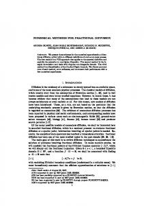
Illustration of the considered principle of using embedded optimization for real-time estimation and feedback control. . .
2
1.1
Illustration of the unconverged (left) and converged (right) state and control trajectories of a multiple shooting method. . . . . .
19
1.2
Block condensing with qpDUNES: trade-off in choosing the block size M for the optimal control of a chain of 4 masses with horizon length N = 200. . . . . . . . . . . . . . . . . . . . . . . . . . . .
37
1.3
Overview of an SQP-type numerical treatment of multiple shooting based real-time optimal control. . . . . . . . . . . . .
37
1.4
Illustration of the receding horizon principle: model predictive control based on the successive solution of optimal control problems. 40
1.5
Illustration of the estimation horizon Te in MHE and the prediction horizon Tp in MPC, and the corresponding state and control trajectories at a given time point (inspired by [313]). . . . 41
1.6
Illustration of the RTI scheme for nonlinear MPC and MHE, including their interactions within the closed-loop system (inspired by [115]). . . . . . . . . . . . . . . . . . . . . . . . . .
48
1.7
Illustration of the scheduling in time of the computations within the RTI framework for embedded optimization (inspired by [313]). 49
2.1
An incomplete overview of numerical integration schemes. . . .
53
2.2
Illustration of single-step versus multistep integration methods.
53
2.3
Structure of the matrix A for different families of RK methods [199]. 58 xix
xx
LIST OF FIGURES
2.4
Illustration of one integration step of a collocation method based on a polynomial interpolation through a set of points ci , i = 1, . . . , q. 61
2.5
The roots of the shifted Legendre polynomials of order 1, 2 and 3, which are respectively used as nodes for the Gauss methods of order 2, 4 and 6. . . . . . . . . . . . . . . . . . . . . . . . . . .
63
The cube toy example setup, used in the multi-rate estimation problem to illustrate a continuous output based MHE implementation. . . . . . . . . . . . . . . . . . . . . . . . . . . . . . . . .
94
2.6
3.1
Illustration of the optimal state and control trajectories, corresponding to the periodic OCP for the nonlinear bioreactor in Eq. (3.33). . . . . . . . . . . . . . . . . . . . . . . . . . . . . 118
4.1
Schematic of the three-stage dynamic system structure, illustrating the workflow in the structure exploiting collocation based integrators. . . . . . . . . . . . . . . . . . . . . . . . . . . . . . 123
4.2
Closed-loop trajectories for the velocity of both trolley and cable, before (dashed) and after extra penalization of high frequencies (solid). . . . . . . . . . . . . . . . . . . . . . . . . . . . . . . . . 130
4.3
Illustration of a closed-loop trajectory of the position and orientation of the quadcopter in a point-to-point motion based on NMPC. . . . . . . . . . . . . . . . . . . . . . . . . . . . . . .
133
Schematic of a multi-stage dynamic system structure, illustrating the workflow in an extended structure exploiting collocation based integrator. . . . . . . . . . . . . . . . . . . . . . . . . . .
134
5.1
Benchmark case study example for optimal control: illustration of a chain of nm = 8 masses connected by springs. . . . . . . .
144
5.2
Chain mass optimal control example: illustration of the different partitioning options to identify the coupled subsystems. . . . .
145
5.3
Comparison of the NMPC closed-loop trajectories for a CMS and a DMS based direct optimal control implementation. . . . . . .
146
6.1
Illustration of Ns fixed integration steps of a collocation scheme over one shooting interval [ti , ti+1 ], including the corresponding equations. . . . . . . . . . . . . . . . . . . . . . . . . . . . . . . . 151
4.4
LIST OF FIGURES
xxi
6.2
An overview of the idea of using lifted collocation integrators, with combined properties from multiple shooting and direct collocation.156
6.3
Illustration of the parallelizable condensing and expansion to efficiently eliminate and recover the collocation variables from the linearized KKT system. . . . . . . . . . . . . . . . . . . . .
160
6.4
Minimizing the control effort versus time optimal OCP formulation for the chain mass example: optimal state and control trajectories (nm = 8). . . . . . . . . . . . . . . . . . . . . . . . 183
6.5
SQP convergence using different lifting techniques for the minimum effort (Gauss-Newton) and time optimal OCP (exact Hessian) with nm = 5. . . . . . . . . . . . . . . . . . . . . . . .
187
Illustration of the divergence of the IN and the convergence of the INIS scheme for the QP in Eq. (7.9). In addition, the asymptotic rate of convergence for INIS can be observed to be the same as for the forward problem. . . . . . . . . . . . . . . . . . . . . . .
195
Illustration of the divergence of the IN and the convergence of the INIS scheme for the NLP in Eq. (7.20). In addition, the asymptotic rate of convergence for INIS can be observed to be the same as for the forward problem unlike the adjoint-free AF-INIS implementation for this NLP example. . . . . . . . . . . . . . .
200
Convergence results of the Gauss-Newton based SQP method with different inexact Newton-type techniques for the chain mass optimal control problem using nm = 4 masses. . . . . . . . . . .
208
Illustration of (a) a general-purpose solver versus (b) the principle of code generation to obtain a custom solver for solving instances of a certain problem formulation (inspired by [222]). . . . . . .
213
8.2
Illustration of the layers in the typical workflow when using the MATLAB interface of the ACADO code generation tool. . . . . . . .
215
8.3
MATLAB code example to implement NMPC using ACADO code generation for the optimal swing-up of an inverted pendulum on top of a cart. . . . . . . . . . . . . . . . . . . . . . . . . . . . .
217
8.4
Schematic of the overhead crane experimental setup [316]. . . .
219
8.5
Illustration of the kite carousel setup in motion at KU Leuven [313].220
7.1
7.2
7.3
8.1
xxii
LIST OF FIGURES
8.6
Sketch of a diesel engine airpath with its main components [41]. . 221
8.7
The miniature race car setup at the University of Freiburg. . .
8.8
Illustration of the two modules in the ACADO code generation tool.223
8.9
Overview of the main ACADO code generation classes to export tailored algorithms. . . . . . . . . . . . . . . . . . . . . . . . . .
9.1
System overview of the investigated two-stage turbocharging concept . . . . . . . . . . . . . . . . . . . . . . . . . . . . . . . . 231
9.2
Illustration of the demonstrator vehicle and the testing track. . . 231
9.3
Validation of the stationary transfer behaviour of the DAE model, based on corresponding measurement data at neng = 2500 min−1 . 237
9.4
Illustration of the closed-loop system on the dSpace MicroAutoBox: NMPC based on ACADO code generation with dead time compensator (DTC) and extended Kalman filter (EKF). . . . . 238
9.5
Overview on design parameters of the different components that are crucial for the real-time feasible NMPC scheme. . . . . . .
9.6
Closed-loop hardware-in-the-loop simulations: comparison of LTI, LTV and NMPC for a step in the boost pressure reference signal. 244
9.7
Steady state measurement data for neng = 2500 min−1 , with an illustration of the change in boost pressure for 10% wastegate actuation. . . . . . . . . . . . . . . . . . . . . . . . . . . . . . .
245
Vehicle dynamometer experiments: closed-loop control for a step in the boost pressure reference signal at engine speed neng = 2500 min−1 . . . . . . . . . . . . . . . . . . . . . . . . . . . . . .
247
9.8
9.9
222
224
243
Vehicle dynamometer experiments: closed-loop control for a step in the boost pressure reference signal for different engine speeds. 248
9.10 Closed-loop experimental results with the vehicle on the road. .
249
List of Tables 2.1
Computational cost of the Newton-type schemes per integration step for a Gauss collocation based method (nk = nx + nz and nw = nx + nu ). . . . . . . . . . . . . . . . . . . . . . . . . . . .
87
2.2
Order of accuracy for the end point and of the continuous output for the 1-, 2- and 3-stage Gauss-Legendre and Radau IIA methods. 91
2.3
Average computation time for approximate infinite horizon NMPC. 94
2.4
Average computation time of one CGN iteration, using respectively an auto generated ACADO solver and MATLAB’s generalpurpose DAE solver ode15s. . . . . . . . . . . . . . . . . . . . .
95
3.1
Theoretical cost comparison of second order sensitivity propagation.112
3.2
Storage cost for the second order sensitivity propagation techniques.113
3.3
The proposed second order sensitivity propagation techniques.
114
3.4
Computation times for a numerical simulation of the chain mass [325] using explicit RK4: TSP-SYM versus FB-FOA sensitivity propagation. . . . . . . . . . . . . . . . . . . . . . .
114
3.5
Parameter values and bounds for the bioreactor. . . . . . . . .
116
3.6
Detailed computation times for exact Hessian based SQP using the explicit RK4 method: TSP-SYM versus FB-FOA sensitivity propagation. . . . . . . . . . . . . . . . . . . . . . . . . . . . . .
119
Average computation times for exact Hessian based SQP using the implicit RK4 method: FB-SYM versus FB-FOA sensitivity propagation. . . . . . . . . . . . . . . . . . . . . . . . . . . . . .
119
3.7
xxiii
xxiv
LIST OF TABLES
4.1
Average computation times: RTI based NMPC of an overhead crane. . . . . . . . . . . . . . . . . . . . . . . . . . . . . . . . .
4.2
Average computation times for RTI based NMPC of an overhead crane, including the penalization of higher frequency state information. . . . . . . . . . . . . . . . . . . . . . . . . . . . . . . 131
4.3
Average computation times for RTI based NMPC of a quadcopter.133
5.1
Computational complexity analysis based on a q-stage collocation scheme: CMS versus DMS with compression (nw = nx + nu ). .
143
5.2
Average computation times for CMS and DMS based RTI schemes on the optimal control example of the chain of masses. . . . . .
147
5.3
Average computation times for the compression procedure in the DMS implementation: Algorithm 4 versus a dense linear solver.
147
5.4
Average timing results for DMS based RTI using different partitions for the chain of masses in coupled subsystems (q = 2). 148
6.1
Comparison of the three collocation based approaches to solve the nonlinear optimal control problem in Eq. (6.7). . . . . . . .
162
6.2
Overview of the presented algorithms for (inexact) Newton based lifted collocation integrators. . . . . . . . . . . . . . . . . . . .
168
6.3
Overview on the different variants of collocation based optimal control algorithms (EH = Exact Hessian, GN = Gauss-Newton). 181
6.4
Average Gauss-Newton based SQP timing results for the minimum effort chain mass OCP using 4-stage Gauss collocation (Ns = 3, q = 4), including different numbers of masses nm and resulting numbers of states nx . . . . . . . . . . . . . . . . . 184
6.5
Detailed timing results for Gauss-Newton based SQP on the minimum effort OCP using nm = 5 masses or nx = 24 states (Ns = 3, q = 4). Note that one iteration of direct collocation (6.7) based on Ipopt takes about 500 ms, and one sparse QP solution using OOQP takes 2.4 s on average. . . . . . . . . . . . . . . . . 185
6.6
Average exact Hessian based SQP timing results for the time optimal chain mass problem using a 4-stage Gauss collocation method (Ns = 3, q = 4), including different numbers of masses nm and resulting numbers of states nx . . . . . . . . . . . . . . .
129
186
LIST OF TABLES
xxv
6.7
Detailed timing results for exact Hessian based SQP on the time optimal OCP using nm = 5 masses or nx = 24 + 1 states (Ns = 3, q = 4). Note that one iteration of direct collocation (6.7) based on Ipopt takes about 300 ms, and one sparse QP solution using OOQP takes 5 s on average. . . . . . . . . . . . . . . . . . 186
7.1
Average timing results per Gauss-Newton based SQP iteration on the chain mass optimal control problem using direct collocation (Ns = 3, q = 4), including different numbers of masses nm and states nx . . . . . . . . . . . . . . . . . . . . . . . . . . .
9.1
207
Comparison of rise time t95 between nonlinear MPC (NMPC), linear time varying (LTV) MPC and linear MPC. . . . . . . . . 243
Introduction Our quality of life, the world’s productivity and its sustainability become more and more determined by the outcome and benefits of process automation. In this domain of automatic control, an important distinction can be made between offline and online tasks. The offline context refers to the problems that can be solved while the process is not yet running, such as the system design, analysis and identification. These activities are not limited by real-time feasibility constraints and typically require considerable amounts of brainwork and computer-human interaction. It includes the implementation and tuning of an automatic control scheme, which can be used to stabilize the system and, for example, steer it to a specific desired state. The latter is referred to as a controller for the dynamic system and executes itself continuously as long as the process is running, i.e., it forms part of the online context. This work is concerned mostly with the online problems related to the control of fast dynamic systems. In addition to the task of computer based automatic control, this includes online state and system parameter estimation. Since many systems operate in a repetitive manner such as, for example, robot arm manipulators or chemical batch processes, the field of iterative learning can play an important role. In this context, the control performance can be improved iteratively based on previous repetitions. In addition to this online information that can be either learned, measured or estimated, there are typically many remaining effects or disturbances which cannot be taken into account. This is the motivation for closing the loop with feedback control, in order to reject such unknown disturbances or any mismatch. A typical case is when the difference between the observed system output and the desired reference is provided as the feedback signal to the controller. A popular viewpoint among researchers on mathematical optimization is that all relevant decisions can and should be cast into an optimization problem. Based on a quantitative representation and suitable approximation of the considered environment, one can typically identify a certain objective or performance index
1
2
LIST OF TABLES
Control actuation reqs.
System
measurements
estimate
Estimation reqs.
Figure 1: Illustration of the considered principle of using embedded optimization for real-time estimation and feedback control. and corresponding constraints or limitations of the problem task. Many of these cases result in static optimization formulations, i.e., without explicitly considering dynamic system evolutions. Application examples of the latter include supply chain management, scheduling or portfolio optimization in economics as well as setpoint calculation, optimal design and regression analysis in modeling and engineering. On the other hand, throughout this thesis, we are more interested in dynamic optimization problems which directly take a model for the dynamic process behaviour into account. In the context of systems engineering, the resulting field is typically referred to as optimal control. The corresponding formulation of a dynamic optimization problem consists of the system dynamics in addition to the problem objective and constraint functions. Examples of optimal control applications include the optimization of an actuation profile in order to perform a certain task, system state and parameter estimation or optimal experiment design. This thesis focuses more specifically on the real-time optimal control of nonlinear small to medium-scale systems with relatively fast dynamics, in order to design an advanced feedback control strategy. For this purpose, both the online estimation and control task can be carried out by embedded dynamic optimization tools. Technically, the term embedded in this case refers to the situation of having any dedicated computer system as part of a larger (typically mechanical or electrical) device, often with limited processing resources and with real-time computing constraints. Figure 1 illustrates the resulting closedloop system. In the context of model predictive control (MPC) and moving horizon estimation (MHE), both the control and estimation task correspond to
LIST OF TABLES
3
an online sequence of dynamic optimization problems based on the receding horizon principle. More specifically, the system parameters or actuation profile are optimized over a certain time horizon using specific measurements and directly taking into account the problem objective, the system dynamics and additional constraints or specifications. These desirable properties also account for the increasing popularity of such dynamic optimization based closed-loop control and estimation techniques. The main disadvantage of embedded optimization based approaches is the resulting computational effort, especially in case of complex nonlinear problems. One needs to solve a large, typically non-convex dynamic optimization problem online and this under strict timing constraints in order to stabilize and control the potentially fast process dynamics. One attractive alternative therefore relies on the explicit and offline computation of the resulting feedback control law, even though this approach unfortunately suffers from the curse of dimensionality when solving this problem and storing the results. Instead, we focus on the direct and online solution of the optimal control problem at each sampling time point. In order to widen the range of applications that can be treated by using such online optimization based techniques, it becomes crucial to use efficient implementations of tailored algorithms on suitable computational hardware. For that reason, this thesis considers the development of real-time feasible numerical algorithms for embedded optimization and it includes open-source software implementations. In the case of complex nonlinear systems with fast dynamics, the numerical simulation of the continuous time differential equations forms an important computational component of any direct optimal control method. In addition, the use of derivative based optimization algorithms results in the need for an efficient propagation of corresponding first and possibly higher order sensitivity information.
Contributions and Outline of this Thesis Let us introduce the structure of this thesis, by describing the specific topics that are discussed in the different chapters as well as their corresponding main contributions.
4
LIST OF TABLES
Chapter 1 - Fast Nonlinear Model Predictive Control and Estimation This chapter introduces the class of dynamic systems and the corresponding optimal control problem formulation, which we handle throughout this thesis. It provides a detailed overview on direct optimal control, including a discussion on the theory and numerical algorithms for nonlinear programming. In addition, the current state of the art is presented regarding tailored solvers for optimal control and online algorithms for fast nonlinear MPC and MHE. More specifically, the Real-Time Iteration (RTI) scheme is introduced which forms the algorithmic framework for many of the new developments in the following chapters. Chapter 2 - Numerical Simulation and Sensitivity Propagation In direct optimal control, one relies on a numerical integration scheme to simulate the system of differential equations. This chapter provides an overview on numerical simulation methods with a specific focus on explicit and implicit Runge-Kutta formulas. Within a Newton-type optimization method, it also becomes crucial to accurately and efficiently evaluate first and possibly higher order sensitivities for each simulation result. Different approaches for performing the corresponding sensitivity analysis are presented and compared for both explicit and implicit integration schemes. A detailed discussion is provided on collocation methods and their efficient implementation for embedded optimization. In addition to the introduction of these concepts, the chapter contributes new optimal control applications based on continuous output. For example, it shows that the continuous output feature allows for an efficient implementation of closed-loop costing for MPC and of an MHE scheme with multi-rate measurements.
LIST OF TABLES
5
The first two chapters introduced and provided an overview of the state of the art regarding numerical algorithms for both embedded optimization and simulation. Building on these concepts, all subsequent chapters present the main contributions of the thesis. Chapter 3 - Symmetric Hessian Propagation Technique This chapter presents an efficient second order differentiation scheme for both discrete- and continuous-time sensitivity analysis. A novel Hessian propagation technique is proposed, which allows one to maintain and exploit the symmetry of the directional derivative contributions for any explicit or implicit integration method. In addition, the discussion in a continuous-time framework allows for a generic sensitivity analysis before applying a numerical discretization scheme. Based on the proposed symmetric sensitivity equations, a new alternative three-sweep Hessian propagation (TSP) scheme will be presented. Unlike the classical forward-backward approach, this technique can result in a considerable reduction of the corresponding memory requirements. An implementation of these symmetric Hessian propagation techniques in the open-source ACADO Toolkit software is presented and its performance is illustrated on the case study of a nonlinear biochemical reactor. Chapter 4 - Structure Exploitation for Linear Subsystems The chapter proposes a new format for defining nonlinear dynamic models and shows how the three-stage structure therein can be strongly exploited especially by implicit integration methods. The structure of linear subsystems in the differential equations is introduced and motivated, followed by a discussion on the consequences for the implementation of direct optimal control methods. Two real-world control examples are used to illustrate the relevance of the proposed three-stage model structure. Numerical experiments show that considerable speedups can be achieved with these structure exploiting integrators, which are implemented as part of the ACADO code generation tool. Chapter 5 - Compression Algorithm for Distributed Multiple Shooting We propose and discuss algorithmic techniques for the efficient implementation of real-time feasible NMPC for decomposable systems based on Distributed Multiple Shooting (DMS). The chapter describes how tailored collocation based integrators with continuous output can be used to efficiently parameterize the coupling between subsystems. In addition, a novel compression algorithm is presented as an effective way of reducing the computational burden for the embedded convex solver. As a particular example, we discuss the numerical exploitation of a tridiagonal coupling structure. The resulting DMS-RTI
6
LIST OF TABLES
scheme is implemented based on the ACADO code generation and is illustrated using the example of a chain of spring connected masses. Already within a serial implementation, the presented algorithm is shown to be able to provide impressive speedups over the conventional scheme. Chapter 6 - Lifted Newton-Type Collocation Integrators We present an implicit extension of the lifted Newton method for collocation schemes and discuss its connection to multiple shooting and direct collocation in a general framework, independent of the Newton-type optimization method. It allows us to interpret this technique as a direct and parallel exploitation of the specific collocation problem structure, for which we discuss both the advantages and disadvantages over classical approaches. In addition, the chapter proposes and analyzes two alternative approaches for inexact Newton based lifted collocation, using either an adjoint derivative propagation or iterated forward sensitivities. A more practical contribution of this chapter is the open-source implementation of these novel lifting schemes within the ACADO code generation tool for embedded optimal control applications. The numerical performance of the proposed algorithmic techniques is illustrated on the benchmark case study of the optimal control for a chain of masses. Chapter 7 - Local Convergence of Inexact Newton with Iterated Sensitivities The chapter presents the Inexact Newton method with Iterated Sensitivities (INIS) in the most general nonlinear programming framework in order to discuss its local convergence. We show that this scheme allows us to recover a strong connection between the local contraction rate of the forward problem and the local convergence properties of the resulting Newton-type optimization algorithm. Unlike the case for standard inexact Newton methods, local contraction based on the Jacobian approximation for the forward problem is necessary and, under mild conditions, even sufficient for local convergence of the INIS optimization scheme. In addition, an adjoint-free (AF-INIS) variant for Newton-type optimization is proposed and its local convergence properties are also studied. This alternative approach is preferable whenever the algorithm can be carried out independently of the respective values for the multipliers corresponding to the equality constraints, but it generally does not preserve the local convergence properties of the forward scheme. Finally, the numerical performance and theoretical results for the presented algorithms are illustrated based on an optimal control case study. Chapter 8 - Open-Source ACADO Code Generation Software As mentioned earlier, an important contribution of the thesis consists of the implementation
LIST OF TABLES
7
of the presented new algorithmic techniques as part of the open-source ACADO code generation software package. This chapter therefore introduces the concept of automatic code generation and discusses the implementation as part of the ACADO Toolkit. In addition, we describe the typical workflow needed to export a tailored optimal control solver and we present the ACADO integrator suite, which forms the main software result of this thesis, in more detail. The tool provides the option to generate a stand-alone, embeddable integrator code with tailored sensitivity propagation, which can be used, e.g., to prototype new algorithms. We discuss some of the many real-world control applications that were made possible by using the newly developed algorithmic techniques within the open-source ACADO code generation tool. Chapter 9 - Two-Stage Turbocharged Gasoline Engine A particularly challenging optimal control application consists of the development of a nonlinear MPC (NMPC) scheme which allows one to meet the tough demands on closedloop control of a two-stage turbocharged gasoline engine. This forms a promising airpath concept in order to reduce the fuel consumption, even though it exhibits strong nonlinear behaviour while having high demands on the control quality and system limitations. The overall goal is that the control scheme makes use of the specific turbocharging architecture to overcome the trade-off between a fast transient raise of the boost pressure and a high specific power. The main contribution in this chapter is the proposed implementation of a real-time feasible NMPC algorithm, with a sampling time of 25 ms, based on an ACADO code generated solver on the dSpace MicroAutoBox as the embedded control hardware. The resulting system is thoroughly validated by performing closedloop simulations and real-world experiments using the implementation within a demonstrator vehicle, both on a dynamometer and on the road.
Chapter 1
Fast Nonlinear Model Predictive Control and Estimation Computation times below one microsecond are typically associated with explicit approaches for linear Model Predictive Control (MPC), for example, as presented in [30] and implemented in the Multi-Parametric Toolbox MPT3 [163]. Given the modern computer architectures and the algorithmic techniques presented in this chapter, it is however possible to achieve such real-time requirements using online, embedded optimization for relatively small applications. Based on the control example from [68], numerical results for Nonlinear MPC (NMPC) simulations with a sampling time below one microsecond have been presented in [270]. Moreover, the proposed direct methods do not suffer from the curse of dimensionality [29] in the same way as explicit solution strategies, such that also larger applications can be considered [315]. Outline The chapter is organized as follows. Section 1.1 briefly presents the class of systems and corresponding dynamic models in which we are interested. The optimal control problem formulation and direct solution approaches are introduced in Section 1.2, followed by an overview on nonlinear programming and Newton-type optimization in Section 1.3. Sequential quadratic programming can rely on structure exploiting solvers for optimal control, as described in Section 1.4. Finally, Section 1.5 presents online algorithms that allow real-time implementations of fast nonlinear model predictive control and estimation.
9
10
1.1
FAST NONLINEAR MODEL PREDICTIVE CONTROL AND ESTIMATION
Controlled Dynamic Systems
Let us start by introducing the class of dynamic systems, which we are interested in throughout this thesis. We mostly consider controlled dynamic systems, i.e., systems that can be manipulated externally. In most of this thesis, the particular nature of this controlled system will not be specified even though the focus is on fast dynamic systems with sampling times in the milli- or even microsecond range. A typical domain of application therefore consists of mechatronic systems (see Chapter 9) but the proposed algorithmic techniques can also be used for other classes of dynamic systems [218]. The system of interest can be described by a deterministic set of differential equations. Note that our discussion further omits other interesting modeling classes for dynamic systems, such as stochastic differential equations [33] or black box modeling [216, 293]. Instead, we focus on systems of Ordinary Differential Equations (ODE) and Differential-Algebraic Equations (DAE) which will be introduced in the next two subsections.
1.1.1
Ordinary Differential Equations
The following definition introduces an implicit ODE system. Definition 1.1 (Ordinary Differential Equations) We define the time t ∈ R, the differential states x(t) ∈ Rnx and control inputs u(t) ∈ Rnu . A system of Ordinary Differential Equations (ODE) to describe the dynamic evolution of this state vector x(t) then reads as 0 = f (x(t), ˙ x(t), u(t)),
(1.1)
where the notation x(t) ˙ = dx(t) dt is used for the differential state derivatives and ∂f the Jacobian matrix ∂ x˙ (·) is assumed to be invertible, ∀t. Note that an explicit system of ODE equations belongs to a special subclass, where the state instead is described by x(t) ˙ = fe (x(t), u(t)),
(1.2)
such that the differential state derivatives x(t) ˙ are defined explicitly. A set of differential equations (1.1) in combination with an initial condition x(t0 ) = x ˆ0 is often referred to as an initial value problem (IVP) 0 = f (x(t), ˙ x(t), u(t)),
x(t0 ) = x ˆ0 ,
(1.3)
CONTROLLED DYNAMIC SYSTEMS
11
given a control trajectory u(t) over a certain time interval t ∈ [t0 , tf ]. The following well-known theorem [69] then describes the existence and uniqueness of a solution x(t) of the IVP in Eq. (1.3). Theorem 1.2 (Picard-Lindelöf Theorem) Consider the initial value problem from Eq. (1.3) for which the Jacobian matrix ∂f ∂ x˙ (·) is assumed to be invertible, corresponding to the ODE system as described in Definition 1.1, and where the continuous-time system dynamics f (·) are Lipschitz continuous in x(t) and continuous in the control inputs u(t). Then, for some value � > 0, there exists a unique solution x(t) to the IVP on the interval [t0 − �, t0 + �]. This result will be important for direct optimal control methods, which typically rely on a piecewise polynomial control parameterization. The theorem can then be applied on each interval where the control inputs u(t) remain continuous, corresponding to a piecewise formulated initial value problem. Note that stronger assumptions will typically be made throughout this thesis on the smoothness of the system dynamics f (·), especially in the context of sensitivity analysis starting with Chapter 2.
1.1.2
Differential-Algebraic Equations
Many modeling techniques do not directly result in an ODE formulation for the dynamic system as in Definition 1.1, but instead result in a set of DAE equations. An interesting example of such an approach for multi-body systems is based on Lagrange mechanics [148, 242, 248], which can be used to directly obtain the DAE system from the Lagrange functions and the algebraic constraints. Definition 1.3 (Differential-Algebraic Equations) We introduce the differential states x(t) ∈ Rnx , control inputs u(t) ∈ Rnu and the algebraic variables z(t) ∈ Rnz to define the following set of Differential-Algebraic Equations (DAE) to describe the behaviour of a dynamic system 0 = f (x(t), ˙ x(t), z(t), u(t)). If the Jacobian matrix
∂f ∂z,x˙ (·)
(1.4)
is invertible, the DAE is said to be of index 1.
The definition corresponds to a fully implicit formulation of a DAE system [65, 66]. It is additionally important to introduce the following common semi-explicit formulation of a DAE system: x(t) ˙ = fe (x(t), z(t), u(t)) 0 = g(x(t), z(t), u(t)),
(1.5)
12
FAST NONLINEAR MODEL PREDICTIVE CONTROL AND ESTIMATION
where the function g(·) defines the algebraic equations. Note that often a relaxed formulation of these algebraic equations is used for dynamic optimization, on which more information can be found in [46, 175, 208]. The DAE system in (1.5) is of index 1 when the Jacobian matrix ∂g ∂z (·) is invertible. We refer to the differential index or differentiation index whenever we mention the index of a DAE system throughout this thesis. Definition 1.4 (Differential index) The index [281] of the DAE in (1.4) is the minimum value for i such that the following set of differential equations 0=
di f (x(t), ˙ x(t), z(t), u(t)), dti
corresponds to an ODE system as described in Definition 1.1. Even though many interesting processes are naturally described by higher index DAEs, we assume all systems in this thesis to be of differential index 1. The class of models based on the Euler-Lagrange equations [242], for example, typically corresponds to DAE systems of index 3 in case of constrained dynamics described by non-minimal coordinates [248]. In practice, one often reformulates higher index DAEs into systems of index 1 or even ODE systems by use of index reduction techniques [241]. The Pantelides algorithm is based on a time differentiation of the constraint equations to obtain an index-1 DAE with associated consistency conditions. The resulting index-reduced system typically retains a reasonable symbolic complexity [148]. Remark 1.5 A third interesting type of systems consists of Partial Differential Equations (PDE), which can depend on multiple other space variables in addition to the time dependency [26]. Note that ODE systems form a special case of DAEs, which in their turn form a special case of PDE systems. In addition, numerical methods for PDEs often rely on a particular discretization technique such as the Method of Lines (MOL) [302]. This particular approach performs the discretization first in space and then in time, resulting in a large structured set of ODEs or DAEs. More information on PDE-constrained optimization and direct optimal control for PDE systems can be found in [37, 167, 252] and references therein. Remark 1.6 A final type consists of Delay Differential Equations (DDE) to describe time-delay systems [98]. They are not further considered in this thesis. Many practical applications involve actuators, sensors or communication networks that result in such delays. It is often crucial to take these delays into account within the control design [224].
CONTROLLED DYNAMIC SYSTEMS
1.1.3
13
Additional Model Parameters
It is often the case that system dynamics are influenced by time-constant model parameters p ∈ Rnp such that the model function would instead be defined as f (x(t), ˙ x(t), u(t), p) in the case of an implicit ODE formulation. It is possible to reformulate such a system into the form of Definition 1.1 by extending the state dimension with additional variables that satisfy x˙ nx +i (t) = 0,
xnx +i (t0 ) = pi ,
i = 1, . . . , np .
In practice, the system dynamics could also be time-dependent f (t, x(t), ˙ x(t), u(t)) which can be considered a special case of including a time-variable model parameter. In a similar fashion, this can be transformed in our standard formulation by defining the following additional state variable x˙ nx +1 (t) = 1,
xnx +1 (t0 ) = t0 .
Finally, it is interesting to note that an IVP has been introduced over a certain time interval t ∈ [t0 , tf ] in Eq. (1.3). Based on the definition t(τ ) := t0 + τ T where T = tf − t0 denotes the time horizon, the system dynamics could however be rescaled in time by using dx dt dx = , dτ dt dτ
or x0 (τ ) = T x(t), ˙
or x(t) ˙ =
resulting in the following scaled dynamics � � 1 0 0=f x (τ ), x(τ ), u(τ ) , T
1 0 x (τ ), T
τ ∈ [0, 1].
In this case, the time horizon could be either a constant T = tf − t0 or a model parameter as introduced earlier. Note that the above reformulations are introduced mainly for notational convenience, while a separate treatment of these model parameters within the presented algorithmic techniques can typically be computationally more efficient.
1.1.4
Numerical Simulation
Based on the results of Theorem 1.2, we know that a unique state trajectory x(t) exists as a solution to the IVP in Eq. (1.3). Note that an extension of this existence and uniqueness theorem can be made to DAE systems such as those in Definition 1.3. More information on this topic can, for example, be found in [279, 280]. In what follows, we often refer to the simulation of differential equations as a numerical approximation of this solution at discrete time points.
14
FAST NONLINEAR MODEL PREDICTIVE CONTROL AND ESTIMATION
An overview on numerical simulation methods can be found in Chapter 2 based on [56, 157, 158]. But we already introduce a few basic concepts in this domain. Let si (ti−1 , xi−1 ) denote the numerical approximation of the solution x(ti ) at time point ti , given the state values xi−1 at time point ti−1 . In that case, si−1 (ti−1 , xi−1 ) = xi−1 holds by definition. Definition 1.7 (Numerical integration error) The local error for the numerical simulation result is defined as e(ti ) = x(ti ) − si (ti−1 , x(ti−1 )), where Tint = ti − ti−1 is typically referred to as the integration step size1 . The global or transported error is accordingly defined as E(ti ) = x(ti ) − si (t0 , x(t0 )), which describes how errors are propagated by the integration scheme. Based on these error definitions, let us additionally introduce the properties of convergence and order for a numerical integration scheme. Definition 1.8 (Order of accuracy) A numerical method is said to be convergent when its values converge to the exact solution for Tint → 0, where Tint represents the integration step size. The method has order P if the local error satisfies P +1 lim e(ti ) = O(Tint ).
Tint →0
Note that P > 0 is a necessary condition for convergence.
1.2
Direct Optimal Control
NMPC is an approach of increasing popularity for real-time control due to the ability to explicitly handle constraints and nonlinear dynamics that characterize the system of interest. This approach is based on the solution of a nonlinear Optimal Control Problem (OCP) at each sampling instant. Numerical methods to solve OCPs are typically classified into three main categories: • Dynamic Programming (DP) schemes are based on Bellman’s principle of optimality in order to propagate a cost-to-go function backwards in time [29]. This approach can either result in the continuous time HamiltonJacobi-Bellman (HJB) [214] partial differential equations or in a discrete time dynamic programming recursion [32]. 1 Unlike the standard notation in [157], the symbol T int is used to denote the integration step size to avoid confusion, e.g., in the optimal control problem parameterization.
DIRECT OPTIMAL CONTROL
15
• Indirect methods for optimal control, also known as first-optimize-thendiscretize approaches are typically based on Pontryagin’s maximum principle [251] to formulate the infinite dimensional first-order necessary optimality conditions. The resulting nonlinear multi-point boundary value problem (BVP) can then be solved numerically [42, 239]. • Direct methods for optimal control, also known as first-discretize-thenoptimize approaches are based on the numerical solution of a finite dimensional optimization problem which corresponds to a discrete approximation of the original continuous-time OCP. It can be shown that this direct approach converges to the original continuous-time solution as the discretization error decreases [119]. There are multiple difficulties when applying an indirect approach in practice, such as the conditioning of the resulting BVP [34]. In addition, direct methods can be implemented in a rather flexible manner while expert knowledge is typically needed whenever the problem formulation is changed within the indirect approach. This work therefore focuses on direct methods for real-time optimal control. The main advantage of dynamic programming is that the globally optimal solution can be found, unlike for the other two schemes. In general, this however comes at the cost of performing a tabulation of the costto-go function on a state space discretization grid. The DP approach therefore suffers from the curse of dimensionality [29] such that it can be applied to systems with only a few states, except for special cases. A more elaborate comparison of all three approaches can be found in [34, 59].
1.2.1
Parametric Optimal Control Problem
This thesis aims at solving parametric optimal control problems (OCPs) as they typically arise in Model Predictive Control (MPC) and Moving Horizon Estimation (MHE), on which more information can be found in Section 1.5. We introduce the following standard problem formulation Z T min `(x(t), u(t)) dt + m(x(T )) (1.6a) x(·), u(·)
s.t.
0
0 = x(0) − x ˆ0 ,
(1.6b)
0 = f (x(t), ˙ x(t), z(t), u(t)),
∀t ∈ [0, T ],
(1.6c)
0 ≥ h(x(t), u(t)),
∀t ∈ [0, T ],
(1.6d)
0 ≥ r(x(T )),
(1.6e)
16
FAST NONLINEAR MODEL PREDICTIVE CONTROL AND ESTIMATION
where x(t) ∈ Rnx denote the differential states, x(t) ˙ are the differential state derivatives, z(t) ∈ Rnz are the algebraic variables and u(t) ∈ Rnu denote the control inputs at time t. The objective in Eq. (1.6a) consists of the functions `(·) and m(·), which typically are referred to as respectively a Lagrange and a Mayertype objective term. The optimization problem depends on the parameter value x ˆ0 through the initial value condition of Eq. (1.6b). The nonlinear dynamics in Eq. (1.6c) are described by an implicit DAE system of index 1, based on Definition 1.3. Additionally, Eqs. (1.6d) and (1.6e) denote respectively the path and terminal inequality constraints. For the sake of simplicity, the algebraic variables only enter the DAE equations (1.6c) in the proposed continuous-time OCP formulation. In practice, both the objective and constraint functions can however additionally depend on these variables and a more general presentation of direct methods for DAEconstrained optimal control can be found in [50, 131, 208]. The time horizon T will typically be considered constant throughout this thesis, even though many interesting OCP problems rely on a variable end time such as, for example, in time-optimal formulations. Note that this can however be transformed in our standard formulation (1.6) based on a rescaling of the dynamics, presented in the previous section. We are mainly interested in the solution u∗ (t, x ˆ0 ) ∀t ∈ [0, T ], which denotes a locally optimal control trajectory to be applied as a function of the current system state x ˆ0 .
1.2.2
Multiple Shooting Parameterization
The continuous-time OCP formulation from (1.6) leaves us with an infinite dimensional optimization problem, which can be tackled using either one of the approaches mentioned earlier. We consider direct optimal control methods based on a parameterization of the state and control trajectory, resulting in a Nonlinear Programming (NLP) formulation which denotes a discrete-time approximation of the original problem. In this chapter, we focus on the direct multiple shooting method which was originally proposed as an approach to solve two-point BVPs [226, 239]. The idea was later adopted by Bock and Plitt into a direct method to solve optimal control problems [51]. Let us introduce the different ingredients for this problem parameterization. Multiple shooting grid discretization points
We first define a grid of N + 1 fixed control 0 = t0 < t1 < . . . < tN = T,
which partition the control horizon into N shooting intervals. For the sake of simplicity, we consider here an equidistant grid over the control horizon
DIRECT OPTIMAL CONTROL
17
T consisting of the collection of time points ti , where ti+1 − ti = N =: Ts for i = 0, . . . , N − 1. Note however that a non-equidistant grid can be treated in a similar fashion within direct multiple shooting.
Control parameterization Next, one needs to decide on a parameterization of the control trajectory u(t) ∀t ∈ [0, T ] by a finite number of parameters which yield a suitable approximation. Typically, one relies on a piecewise polynomial approximation given the N shooting intervals of the control discretization grid [209]. For notational convenience, we use the simplest form based on a piecewise constant parameterization u(τ ) = ui
for τ ∈ [ti , ti+1 ).
State parameterization The multiple shooting grid and the control parameterization result in a natural representation of the state trajectory as the solution to N coupled initial value problems 0 = f (x(τ ˙ ), x(τ ), z(τ ), ui ),
x(ti ) = xi ,
τ ∈ [ti , ti+1 ),
(1.7)
for i = 0, . . . , N −1 and x(0) = x ˆ0 is defined. When the initial condition for x(ti ) refers to the solution of the previous IVP, one obtains a sequential approach to direct optimal control which is typically referred to as single shooting [288]. This method relies on a sequential evaluation of the full state trajectory, where the solution of each IVP depends on the simulation result of the previous one. Instead, the direct multiple shooting method introduces additional state variables xi ∈ Rnx for i = 0, . . . , N on the grid points in order to explicitly couple the initial value problems. Note that this method is consistent with the sequential approach by including the continuity constraints xi+1 = si+1 (ti , xi , ui ),
i = 0, . . . , N − 1,
where s(·) denotes a numerical simulation for the IVP (1.7) given the value x(ti ) = xi . For notational convenience, we further consider the same integration method to be used to solve the IVP on each interval of the equidistant multiple shooting grid. We therefore rewrite these conditions as xi+1 = φ(xi , ui ),
i = 0, . . . , N − 1,
resulting in a discrete-time and autonomous representation of the system dynamics. Throughout this thesis, we refer to the function φ(·) as the result of calling an integrator.
18
FAST NONLINEAR MODEL PREDICTIVE CONTROL AND ESTIMATION
Path inequality constraints The inequality constraints (1.6d) need to be imposed on the full time horizon [0, T ], resulting in a semi-infinite programming problem [165] which is generally not tractable. More information on how to practically avoid violations of these semi-infinite path constraints within direct optimal control methods can, for example, be found in [254]. For notational convenience, we simply relax these path constraints by imposing them directly on the shooting grid points 0 ≥ h(xi , ui ),
i = 0, . . . , N − 1,
which in practice often already limits the violations of these constraints in between the grid points of a sufficiently fine discretization. Nonlinear Programming (NLP) formulation To arrive at the finite dimensional NLP approximation of the OCP, we additionally approximate the continuous time objective (1.6a) by the discrete time sum N −1 X
l(xi , ui ) + m(xN ),
i=0
which can be obtained, for example, by extending the dynamics (1.6c) with quadrature states [166]. The discrete time stage cost can be evaluated efficiently as part of the solution of the state trajectory IVP [208]. Based on the above ingredients for parameterization of the OCP in Eq. (1.6), the resulting structured Nonlinear Program (NLP) reads min X, U
s.t.
N −1 X
l(xi , ui ) + m(xN )
(1.8a)
i=0
0 = x0 − x ˆ0 ,
(1.8b)
0 = xi+1 − φ(xi , ui ),
i = 0, . . . , N − 1,
(1.8c)
0 ≥ h(xi , ui ),
i = 0, . . . , N − 1,
(1.8d)
0 ≥ r(xN ),
(1.8e)
> > nx with state trajectory X = [x> and control trajectory 0 , . . . , xN ] where xi ∈ R > > > nu U = [u0 , . . . , uN −1 ] where ui ∈ R . When one addresses this problem directly in a nonlinear optimization framework, the variables in X and U generally represent a feasible state and control trajectory only at convergence. This is additionally illustrated in Figure 1.1, which visualizes the converged and unconverged multiple shooting trajectories.
DIRECT OPTIMAL CONTROL
19
Figure 1.1: Illustration of the unconverged (left) and converged (right) state and control trajectories of a multiple shooting method. Remark 1.9 Direct multiple shooting is often referred to as a simultaneous approach because the optimization and simulation problem are solved together. In comparison, a sequential approach carries out the simulation task separately from solving the optimization problem. This technique is also known as single shooting [288], where a reduced OCP formulation is obtained after replacing the variables xi by the results of a forward simulation (1.7). Since the variable space of this problem is strongly reduced in dimension from (N + 1)nx + N nu to only N nu , the task of solving this NLP appears to be simplified. However, it has been shown [8] that the cost per Newton iteration can be made equal for both approaches because of the sparsity structure in (1.8). Advantages of multiple shooting over single shooting are the stronger flexibility in initializing the problem and parallelizing the algorithm, and the improved convergence properties especially in the case of an unstable system [8].
1.2.3
Direct Transcription Methods
Direct transcription methods formulate an optimization problem where the equations to simulate the system dynamics are embedded as nonlinear equality constraints [34, 250]. This is therefore an alternative simultaneous approach for direct optimal control. These methods have the same property of representing a feasible state and control trajectory only at convergence, as illustrated by Figure 1.1 for multiple shooting. More specifically, this approach requires that all intermediate results for numerical simulation need to be lifted as additional degrees of freedom [8]. A rather popular example of such a direct transcription method is direct collocation [39, 160], where the additional constraints and variables are based on the equations to define the corresponding collocation polynomials. This family of collocation methods is discussed for numerical simulation as part of Chapter 2. The efficient solution of the resulting direct collocation NLP will be the topic of discussion in Chapter 6.
20
FAST NONLINEAR MODEL PREDICTIVE CONTROL AND ESTIMATION
Let us introduce the following general representation of a numerical simulation method applied to one shooting interval xi+1 = F (xi , zi , ui ) 0 = G(xi , zi , ui ), where zi for i = 0, . . . , N − 1 denote all intermediate variables of the integration scheme to solve the IVP (1.7). They are defined either explicitly or implicitly by the function G(·) and they are necessary to evaluate the numerical simulation result xi+1 = F (xi , zi , ui ). The resulting structured NLP reads as min
X, U, Z
s.t.
N −1 X
l(xi , ui ) + m(xN )
(1.9a)
i=0
0 = x0 − x ˆ0 ,
(1.9b)
0 = xi+1 − F (xi , zi , ui ),
i = 0, . . . , N − 1,
(1.9c)
0 = G(xi , zi , ui ),
i = 0, . . . , N − 1,
(1.9d)
0 ≥ h(xi , ui ),
i = 0, . . . , N − 1,
(1.9e)
0 ≥ r(xN ).
(1.9f)
Even though this NLP formulation is much larger than the multiple shooting type problem (1.8), direct transcription methods have the important property that the sparsity of the dynamics can typically be preserved within the additional constraints (1.9c) and (1.9d). In addition, the solution of the augmented NLP formulation in Eq. (1.9) relies on the evaluation of the functions F (·) and G(·) and their respective derivatives. For direct multiple shooting, one needs to propagate the sensitivities directly through the dynamics as discussed in the next chapter. On the other hand, multiple shooting can rely on any (generalpurpose) solver to simulate the system dynamics. Many of these solvers include step size and order control to provide guarantees regarding the accuracy of the simulation results, which typically allows a reduced overall number of integration steps [158]. See [7, 27, 166] for more details about the use of step size control, especially within direct optimal control. Alternatively, it is less trivial but not impossible to extend the direct transcription formulation in Eq. (1.9) with such an adaptive approach [36, 215, 246]. A more detailed comparison between the multiple shooting method and the direct collocation approach can be found as part of Chapter 6 on lifted collocation integrators.
NONLINEAR PROGRAMMING METHODS
1.3
21
Nonlinear Programming Methods
This section introduces a few important concepts and algorithmic techniques from the field of nonlinear optimization, with a focus on the tools needed for real-time optimal control applications. A detailed overview can be found in [39, 112, 232] and references therein. For this purpose, we consider a compact Nonlinear Programming (NLP) formulation that covers both optimal control problems in Eqs. (1.8) and (1.9). All optimization variables are collected into the vector y ∈ Rny such that the standard NLP form reads min
ψ(y)
(1.10a)
s.t.
0 = c(y)
(1.10b)
0 ≥ h(y),
(1.10c)
y
where ψ : Rny → R, c : Rny → Rneq , h : Rny → Rnineq . Because of the numerical methods presented in this section and also further in this thesis, we introduce the following assumption on all problem functions. Assumption 1.10 The objective ψ(y) and constraint functions c(y) and h(y) in the NLP from Eq. (1.10) are twice continuously differentiable in all arguments.
1.3.1
Optimality Conditions
We are interested in the conditions for optimality of the NLP in Eq. (1.10), which is not necessarily convex in general. Because of our focus on real-time feasible implementations of direct optimal control methods, it will typically be sufficient to find a locally optimal solution. Definition 1.11 (Feasible point) A vector y¯ is called a feasible point, iff the constraints in Eqs. (1.10b) and (7.21c) are satisfied 0 = c(¯ y ),
0 ≥ h(¯ y ).
The feasible set Ω is then defined to include all such points, i.e., Ω = {y ∈ Rny | 0 = c(y), 0 ≥ h(y)}. Definition 1.12 (Local minimizer) A vector y ? is called a local minimizer or a locally optimal solution, iff this point is feasible y ? ∈ Ω and there exists a local neighborhood N of y ? , i.e., an open ball around y ? , such that ∀y ∈ Ω ∩ N : ψ(y) ≥ ψ(y ? ).
(1.11)
22
FAST NONLINEAR MODEL PREDICTIVE CONTROL AND ESTIMATION
A local minimizer can also be the global solution when the latter condition holds for the complete feasible set Ω instead of a local neighborhood N . Even though many recent developments have been made with respect to algorithms for global optimization [113, 174], they are generally not yet tractable especially for realtime optimal control of nontrivial systems with relatively fast dynamics. The online optimization algorithms in this thesis are even based on the approximative solution of the optimization problem at one sampling time, starting from the approximative solution of the previous problem. Based on a good initialization and a sufficiently high sampling rate, these methods result in a local convergence over time as will be discussed in Section 1.5. In order to present the optimality conditions that characterize a local minimizer, we first need to introduce a few more concepts. Definition 1.13 (Active constraint) An inequality constraint hi : Rny → R is called active in a feasible point y¯ ∈ Ω, iff hi (¯ y ) = 0. The index set A(¯ y ) ⊂ {1, . . . , nineq } of active inequality constraints is typically referred to as the active set. Definition 1.14 (LICQ) The linear independence constraint qualification (LICQ) holds at a feasible point y¯ ∈ Ω, iff all vectors ∇ci (¯ y ) for i ∈ {1, . . . , neq } and ∇hi (¯ y ) for i ∈ A(¯ y ) are linearly independent. Note that weaker constraint qualifications exist as discussed in [232], even though the above LICQ condition can often be satisfied in practice and will therefore be sufficient for our purposes. Let us introduce the Lagrangian function, which plays an important role in the optimality conditions. Definition 1.15 (Lagrangian function) For the NLP formulation in Eq. (1.10), the Lagrangian function is defined as L(y, λ, ν) = ψ(y) + λ> c(y) + ν > h(y).
(1.12)
The vectors λ ∈ Rneq and ν ∈ Rnineq denote the Lagrange multipliers or the dual variables, which can be interpreted as shadow prices [232]. The following theorem then specifies the first order necessary conditions (FONC) to characterize a local minimizer. Theorem 1.16 (Karush-Kuhn-Tucker (KKT) conditions) Let y ? be a local minimizer for the NLP in (1.10) which satisfies the LICQ condition. Then,
NONLINEAR PROGRAMMING METHODS
23
there exist Lagrange multipliers λ? and ν ? for which holds ∇y L :
∇ψ(y ? ) + ∇c(y ? )λ? + ∇h(y ? )ν ? = 0
(1.13a)
∇λ L :
c(y ? ) = 0
(1.13b)
∇ν L :
h(y ? ) ≤ 0
(1.13c)
ν? ≥ 0
(1.13d)
νi? hi (y ? ) = 0,
i = 1, . . . , nineq .
(1.13e)
A primal-dual solution (y ? , λ? , ν ? ) is called a KKT point. ∂c Note that we use the notation ∂y (¯ y ) = ∇c(¯ y )> = cy (¯ y ) to denote a Jacobian. When the LICQ holds at the local minimizer y ? , the optimal Lagrange multipliers (λ? , ν ? ) are unique. A proof for this and Theorem 1.16 can be found in [232]. Eqs. (1.13b) and (1.13c) are typically referred to as the primal feasibility conditions, while Eq. (1.13a) denotes the stationarity conditions, Eq. (1.13d) states the dual feasibility and Eq. (1.13e) forms the complementarity conditions. In the case of a convex NLP, every local minimizer is also a global solution and these first order KKT conditions are then both necessary and sufficient. For the general non-convex form, we introduce the second order sufficient conditions (SOSC) after defining strict complementarity.
Definition 1.17 (Strict complementarity) Let (y ? , λ? , ν ? ) be a KKT point of the NLP in (1.10). Strict complementarity then holds for this solution if all active inequality constraints are strictly active, i.e., if νi? > 0 for all i ∈ A(y ? ). In order to state the second-order sufficient conditions, we additionally define the critical cone at a KKT point. Definition 1.18 (Critical cone) Let (y ? , λ? , ν ? ) be a KKT point of the NLP in (1.10), then the critical cone corresponds to the set ? > ∇ci (y ) d = 0, ∀i ∈ {1, . . . , neq } d ∈ C(y ? , ν ? ) ⇔ ∇hi (y ? )> d = 0, ∀i ∈ A(y ? ) with νi? > 0 (1.14) ∇hi (y ? )> d ≤ 0, ∀i ∈ A(y ? ) with νi? = 0. Theorem 1.19 (Second-order sufficient conditions) Let (y ? , λ? , ν ? ) be a KKT point of the NLP in (1.10). If the Hessian of the Lagrangian is strictly positive definite in the directions of the critical cone, i.e., if the following condition holds d> ∇2y L(y ? , λ? , ν ? ) d > 0,
∀d ∈ C(y ? , ν ? ), d 6= 0,
then the point y ? is a local minimizer of (1.10).
24
FAST NONLINEAR MODEL PREDICTIVE CONTROL AND ESTIMATION
We then define a regular KKT point, based on the collection of conditions which we assume throughout this thesis, to simplify our discussion. Definition 1.20 (Regular KKT point) A local minimizer of the constrained NLP in (1.10) is called a regular KKT point (y ? , λ? , ν ? ) if LICQ, strict complementarity and SOSC are satisfied at this point. Assumption 1.21 The local minimizers of the optimal control problems in Eqs. (1.8) and (1.9) are assumed to be regular KKT points.
1.3.2
Newton-Type Optimization
An overview of algorithms for nonlinear optimization can be found in [39, 112, 232]. In this thesis, we only consider Newton-type optimization algorithms to solve the NLP (1.10) with a focus on Sequential Quadratic Programming (SQP). In order to discuss optimization algorithms and their convergence properties, we briefly introduce some of the common convergence rates [232]. Definition 1.22 (q-linear convergence rate) Let y (k) ∈ Rny denote the iterates where y (k) → y ? for k → ∞. We say that y (k) converges q-linearly if there exists a constant r ∈ (0, 1) such that ky (k+1) − y ? k ≤ r, ky (k) − y ? k
∀k ≥ k¯ ∈ N.
Definition 1.23 (q-superlinear convergence rate) Let y (k) ∈ Rny denote the iterates where y (k) → y ? for k → ∞. We say y (k) converges q-superlinearly if ky (k+1) − y ? k = 0. k→∞ ky (k) − y ? k lim
Definition 1.24 (q-quadratic convergence rate) Let y (k) ∈ Rny denote the iterates where y (k) → y ? for k → ∞. We say that y (k) converges q-quadratically if there exists a constant K ∈ (0, ∞) such that ky (k+1) − y ? k ≤ K, ky (k) − y ? k2
∀k ≥ k¯ ∈ N.
Equality constrained optimization Let us first consider the equality constrained case, i.e., nineq = 0 and L(y, λ) = ψ(y) + λ> c(y). Newton-type optimization algorithms are based on the direct
NONLINEAR PROGRAMMING METHODS
25
solution of the first order necessary conditions ∇y L(y, λ) = 0 c(y) = 0, from Theorem 1.16 and this using a Newton-type root finding method [79, 82]. An exact Newton iteration on these KKT conditions reads as � 2 �� � � � ¯ c> (¯ ¯ ∆y ∇y L(¯ y , λ) ∇y L(¯ y , λ) y y) , (1.15) =− ∆λ c(¯ y) cy (¯ y) 0 | {z } {z } | ¯ = F (¯ y ,λ)
¯ = J(¯ y ,λ)
∂c where cy (¯ y ) := ∂y (¯ y ) = ∇c(¯ y )> denotes the Jacobian matrix and the values y¯ ¯ denote the current primal and dual variables. To arrive at a more compact and λ � � ¯ ∆y = −F(¯ ¯ notation, we refer to the exact Newton iteration as J(¯ y , λ) y , λ) ∆λ ¯ := ∂F (¯ ¯ based on the Jacobian matrix J(¯ y , λ) y , λ). ∂(y,λ)
There exist many Newton-type optimization methods that are based on specific approximations of the KKT matrix J(·) in Eq. (1.15), in order to result in desirable convergence properties at a considerably reduced computational cost. Such an approach can be based on the approximation of the Hessian of the ¯ using only first order derivative information ˜ ≈ H := ∇2y L(¯ Lagrangian H y , λ) as performed in the family of Quasi-Newton methods [80, 232]. A compact overview of Hessian approximation schemes will be provided further in the context of SQP methods. Other Newton-type optimization algorithms even use an inexact Jacobian matrix for the equality constraints [49, 94, 175], as will be the topic of discussion in Chapter 7. One iteration of any such inexact Newton-type method can be written as follows in the compact form � � ¯ ∆y = −F(¯ ¯ ˜ y , λ) J(¯ y , λ), (1.16) ∆λ ¯ ≈ J(¯ ¯ := ∂F (¯ ¯ ˜ y , λ) based on a Jacobian approximation J(¯ y , λ) ∂(y,λ) y , λ) and where the function F(·) denotes the KKT right-hand side in Eq. (1.15). The convergence of this scheme then follows the classical and well-known local contraction result from [44, 82, 94, 252]. We use a particular version of this theorem from [86], providing sufficient and necessary conditions for the existence of a neighborhood of the solution where the Newton-type iteration converges. For this purpose, we consider the full-step iteration ˜ w) w ¯+ = w ¯ − J( ¯ −1 F(w), ¯
(1.17)
26
FAST NONLINEAR MODEL PREDICTIVE CONTROL AND ESTIMATION
¯ is defined. We first present where the current primal-dual iterate w ¯ := (¯ y , λ) a classical result from nonlinear systems theory [218], which we do not prove here. Let ρ(P ) denote the spectral radius, i.e., the maximum absolute value of the eigenvalues for the square matrix P . Lemma 1.25 (Linear stability analysis) We regard an iteration of the form w ¯ + = G(w) ¯ with G(·) a continuously differentiable function in a neighborhood of a fixed point w? = G(w? ). If � the spectral radius of the Jacobian matrix ∂G is smaller than one, ρ ∂w (w? ) < 1, then the fixed point is asymptotically stable. More specifically, the iterates converge to w? with a q-linear convergence � ∂G rate with asymptotic contraction factor ρ ∂w (w? ) . On the other hand, if � ∂G ρ ∂w (w? ) > 1, then the fixed point is unstable and the iterations can move away, even if the initial guess is arbitrarily close to w? . ˜ −1 F(w), We can apply this lemma to the Newton-type iteration G(w) = w − J(w) ˜ based on the extra assumption that the Jacobian approximation J(·) is continuously differentiable, in addition to being invertible. This assumption is satisfied for an exact Newton method, for schemes based on fixed Jacobian approximations as well as for the Gauss-Newton (GN) method for nonlinear least squares optimization, which will be introduced further. We can now present the main local contraction theorem. Theorem 1.26 (Local Newton-type contraction) We consider the twice continuously differentiable function F(y, λ) from Eq. (1.15) given Assumption 1.10 and the regular KKT point F(y ? , λ? ) = 0. We apply the Newton-type iteration ¯ ≈ J(¯ ¯ is assumed ˜ y , λ) from Eq. (1.16), where the Jacobian approximation J(¯ y , λ) to be continuously differentiable and invertible in a neighborhood of the solution. If all eigenvalues of the iteration matrix have a modulus smaller than one, i.e., if the spectral radius � ˜ ? , λ? )−1 J(y ? , λ? ) − 1 < 1, κ? := ρ J(y (1.18) then this fixed point (y ? , λ? ) is asymptotically stable. In addition, the iterates ¯ converge linearly to the KKT point (y ? , λ? ) with the asymptotic contraction (¯ y , λ) rate κ? when initialized sufficiently close. On the other hand, if κ? > 1, then the fixed point (y ? , λ? ) is unstable. Proof. We apply Lemma 1.25 directly to the Newton-type iteration G(w) = ˜ −1 F(w), where w := (y, λ) denotes all the optimization variables. w − J(w) First, we observe that w? = G(w? ) holds, due to F(w? ) = 0. We then compute
NONLINEAR PROGRAMMING METHODS
27
the Jacobian of G(·) at the fixed point w? : ∂G ? ∂(J˜−1 ) ? ˜ ? )−1 ∂F (w? ) (w ) = 1 − (w ) F(w? ) −J(w | {z } ∂w ∂w ∂w =0
˜ ? )−1 J(w? ), = 1 − J(w where 1 denotes the identity matrix. In summary, the spectral radius of the iteration matrix is a tight criterion for local Newton-type convergence. If it is larger than one, the Newton-type method diverges, while if it is smaller than one, the method converges. More advanced convergence results, under weaker assumptions, can be found in [77, 82, 206]. Note that the exact Newton method from Eq. (1.15) has a locally quadratic convergence rate [79, 82]. Even though Theorem 1.26 holds for any method that satisfies the corresponding conditions, other Newton-type variants exist that, for example, allow locally superlinear convergence [94, 143] based on quasi-Newton Jacobian updates. In the case of optimal control for differentialalgebraic equations, even quadratic convergence rates have been shown for a specific Newton-type optimization method with inexact derivatives in [175]. Remark 1.27 Results on global convergence will not be discussed throughout this thesis, even though a lot of research has focused on globalization strategies such as line search, trust-region or filter methods [39, 112, 232]. In the context of embedded optimization where a good initial guess is typically available from the previous iterate of the online algorithm, local convergence results and contraction rates instead become more valuable in practice [90]. Inequality constrained optimization In order to extend Newton-type optimization algorithms to the inequality constrained case, one needs to decide on a way to treat these inequality constraints in the KKT conditions (1.13). We briefly discuss two popular classes of algorithms for nonlinear optimization: Interior Point (IP) methods and Sequential Quadratic Programming (SQP). Interior point or barrier methods are among the most powerful algorithms for nonlinear optimization, especially for large-scale programming problems [232]. The main idea is to approximate the non-smooth complementarity condition in Eq. (1.13e) by the smooth version νi hi (y) = τ for i = 1, . . . , nineq and where τ > 0 is typically referred to as the barrier parameter. The resulting perturbed KKT system is subsequently solved for a sequence of positive barrier parameter
28
FAST NONLINEAR MODEL PREDICTIVE CONTROL AND ESTIMATION
values for which τ → 0. The corresponding primal and dual solutions y¯(τ ), ¯ ) and ν¯(τ ) can then be shown to locally coincide with the primal-dual λ(τ central path, which converges to the solution of the original KKT system (1.13). This approach can also be interpreted as solving the KKT conditions of a barrier problem that handles the inequality constraints by means of a barrier function, and this for a sequence of positive parameter values. As the name suggests, the iterates of an IP method remain in the strict interior of the feasible region even though an infeasible start is typically possible based on a slack reformulation. More information on this family of optimization algorithms can be found in [39, 232, 327]. A widely used general-purpose IP method is implemented for sparse NLPs in the open-source code Ipopt [317, 318]. Unlike the smoothening technique of interior point methods, Sequential Quadratic Programming (SQP) is based on sequentially approximating the NLP by a quadratic subproblem. The combinatorial complexity of determining the correct active set then needs to be addressed for each simpler subproblem. This approximation is typically done using a convex Quadratic Programming (QP) subproblem. But generalizations of this idea exist under the collective name of Sequential Convex Programming (SCP) as discussed in [304, 305], including Sequential Semidefinite Programming (SSDP) in [120, 300]. One important motivation for SQP methods is based on the observation that for a fixed active set, Newton iterations on the KKT optimality conditions (1.15) can be interpreted as solving equality constrained QP approximations of the original NLP [232]. Unlike IP techniques, which do not easily benefit from a good initial guess [296], the natural warm-starting capabilities of SQP methods make them especially popular for embedded optimization [90]. This thesis therefore focuses on the family of SQP methods for nonlinear programming and a compact overview is provided next.
1.3.3
Sequential Quadratic Programming
An SQP method applied to the general NLP in Eq. (1.10) proceeds in each iteration by solving the following QP subproblem min ∆y
s.t.
1 > ∆y H∆y + ∇y ψ(¯ y )> ∆y 2
(1.19a)
0 = c(¯ y ) + cy (¯ y )∆y
| λQP
(1.19b)
0 ≥ h(¯ y ) + hy (¯ y )∆y
| νQP ,
(1.19c)
∂c where cy (¯ y ) := ∂y (¯ y ) and hy (¯ y ) := ∂h y ) denote the constraint Jacobian ∂y (¯ ¯ ν¯) matrices. In the case of an exact SQP method, the matrix H = ∇2y L(¯ y , λ,
NONLINEAR PROGRAMMING METHODS
29
denotes the Hessian of the Lagrangian. The current primal and dual variables are updated based on the solution of the QP (1.19) as follows y¯+ = y¯ + α∆y ¯+ = λ ¯ + α(λQP − λ) ¯ λ ν¯+ = ν¯ + α(νQP − ν¯), where the step size α is typically determined using a globalization strategy [232]. Throughout this thesis, we omit such globalization techniques in the context of online algorithms for embedded optimization (see Remark 1.27) and we therefore consider α = 1. As mentioned earlier, we have a special focus on SQP methods for real-time optimal control applications because of their warmstarting capabilities. In addition, SQP methods satisfy linearized versions of the inequality constraints (1.19c) in each iteration which will show to be especially important within online algorithms for Nonlinear MPC in Section 1.5. In what follows, we provide a compact overview of Hessian approximation techniques and local convergence results for SQP methods. Hessian approximation techniques Exact Hessian based SQP methods rely on the computation of the second ¯ ν¯) which can be computationally expensive in order derivatives H = ∇2y L(¯ y , λ, general [268]. Many popular variants of SQP methods are therefore based on Hessian approximation techniques that often result in a slower local convergence rate but this at a considerably lower computational cost per iteration, typically resulting in a reduction of the overall computation time. An important class of such SQP algorithms uses exact constraint Jacobians but approximates the Hessian matrix H, using an update formula based on first order derivative information [255]. These schemes are better known as Quasi-Newton methods and the most widely used formula is the BroydenFletcher-Goldfarb-Shanno (BFGS) update [232]. Quasi-Newton methods are very successful for nonlinear optimization, e.g., in the form of the software packages SNOPT [133] and MUSCOD-II [209]. Based on our experience, these techniques are however less recommendable in the context of real-time optimal control due to their fluctuating convergence rate. For example, after a state jump due to external noise, the Hessian approximation can be poor such that many BFGS updates are needed to recover a reasonable convergence rate. This is in conflict with the real-time or deterministic run-time requirements as they will be specified in Section 1.5.
30
FAST NONLINEAR MODEL PREDICTIVE CONTROL AND ESTIMATION
Another popular Hessian approximation technique is used in the Constrained or Generalized Gauss-Newton (GGN) method as presented in [48, 292]. This scheme is applicable to optimization problems with a (nonlinear) least squares type objective ψ(y) = 12 kR(y)k22 which is quite common in optimal control problems. The function R(·) is often referred to as the residual function, since it typically denotes an error or misfit [48]. The GGN method approximates the Hessian of the Lagrangian using the matrix ¯ ν¯), HGN (¯ y ) = Ry (¯ y )> Ry (¯ y ) ≈ ∇2y L(¯ y , λ,
(1.20)
where Ry (¯ y ) := ∂R y ) denotes the Jacobian of the residual at the current ∂y (¯ optimization values y¯. Note that the Gauss-Newton Hessian approximation HGN (y) does not depend on the dual variables and is therefore also called a multiplier-free approach. This is an important advantage in practice, because it means that its performance does not depend on the availability of a good initial guess for these Lagrange multipliers. The resulting objective (1.19a) in the QP subproblem reads as 1 1 kR(¯ y ) + Ry (¯ y )∆yk22 = ∆y > Ry (¯ y )> Ry (¯ y )∆y + R(¯ y )> Ry (¯ y )∆y + constant 2 2 =
1 > ∆y HGN ∆y + ∇y ψ(¯ y )> ∆y + constant. 2
The GGN method is based on the observation that the matrix in Eq. (1.20) forms a good Hessian approximation, as long as the residual evaluations R(·) remain small or the problem functions have small second order derivatives [232]. This is typically the case in parameter estimation problems or tracking formulations of optimal control, which are two important application examples [48]. In case of a perfect fit, i.e., zero residuals at the solution, a locally quadratic convergence rate can even be observed. In all other situations, the GGN method results in a typically (fast) linear convergence rate. Subproblem convexification For a regular KKT point, based on the SOSC condition from Theorem 1.19, the Hessian of the Lagrangian is locally positive definite on the null space of the active constraints. This, however, does not mean that each QP subproblem (1.19) will be convex when initializing the SQP method further away from this KKT point. In general, regularization or convexification techniques are therefore used to result in convex QP subproblems [133, 134, 232]. Both of the aforementioned Hessian approximation techniques allow one to avoid this issue in a rather convenient way. The Gauss-Newton Hessian approximation is positive definite
NONLINEAR PROGRAMMING METHODS
31
by definition, if ∂R ∂y has full rank, and therefore does not require regularization. Quasi-Newton methods often rely on a modified update formula in order to maintain a positive definite Hessian approximation as discussed in [232]. In case of optimal control problems such as Eq. (1.8) for direct multiple shooting, it is important to apply an efficient convexification technique that additionally preserves the sparsity structure of the problem as proposed in [310]. Alternative inexact SQP methods In addition to Quasi-Newton and Gauss-Newton methods, even fixed Hessian approximations are sometimes used in practice because of computational advantages. An SQP scheme with a fixed Hessian approximation is equivalent to a preconditioned proximal gradient method with fixed step size [230, 336] as discussed in [193]. Another important family of algorithms relies on the approximation of the constraint Jacobian matrices in addition to the Hessian approximation technique, in order to further reduce the computational effort [49, 94, 324]. The SQP subproblem then reads as min ∆y
s.t.
1 > ¯ ν¯)> ∆y ∆y H∆y + a(¯ y , λ, 2
(1.21a)
0 = c(¯ y ) + A ∆y
| λQP
(1.21b)
0 ≥ h(¯ y ) + B ∆y
| νQP ,
(1.21c)
based on the Jacobian approximations A ≈ cy (¯ y ) and B ≈ hy (¯ y ). These methods typically rely on adjoint derivative computation techniques [141] to ¯ ν¯) = ∇y L(¯ ¯ ν¯) − A> λ ¯ − B > ν¯ efficiently evaluate the modified gradient a(¯ y , λ, y , λ, in the QP objective (1.21a). This gradient correction is needed in order to allow local convergence to solutions of the original NLP [49, 94, 324]. These algorithms will therefore be referred to as adjoint based inexact SQP methods, as discussed further as part of Chapter 7. Local convergence results This thesis will focus on local convergence results for equality constrained optimization problems such as those in Theorem 1.26. This is motivated by the following standard result on the local stability of the active set within SQP type methods [49, 52, 232, 284]. Theorem 1.28 (Stability of QP active set) Consider a local minimizer (y ? , λ? , ν ? ) of the NLP (1.10), for which LICQ and strict complementarity
32
FAST NONLINEAR MODEL PREDICTIVE CONTROL AND ESTIMATION
holds, and the Hessian matrix H in the QP subproblem is positive definite on ¯ ν¯) is the nullspace of the linearized active constraints. If a current iterate (¯ y , λ, ? ? ? sufficiently close to the minimizer (y , λ , ν ), then the solution of the QP (1.19) has the same active set as the original NLP. The fact that the active set remains stable near a solution allows us to study local convergence properties of SQP methods for a given active set. This explains why exact Hessian schemes locally converge quadratically, Quasi-Newton methods typically result in a superlinear convergence while other techniques such as GaussNewton methods converge linearly based on standard Newton-type convergence theory [232]. This is also the reason why our presentation in Chapter 6 and 7 considers equality constrained optimization problems when discussing local Newton-type convergence. Even though Theorem 1.28 is crucial to locally obtain the equivalence of the SQP method with a Newton-type algorithm, the region of full step convergence is typically much larger than the neighborhood where the QP active set is always the same [49].
1.4
Tailored Convex Solvers for Optimal Control
In the previous section, we gave an overview on Nonlinear Programming (NLP) and the popular Newton-type optimization algorithms. When applying an SQP method to the multiple shooting type OCP in Eq. (1.8), each iteration solves the following structured QP subproblem min
∆X, ∆U
N −1 X i=0
� �> � � � � 1 ∆xi ∆xi > ∆xi Hi + gi ∆ui ∆ui 2 ∆ui
1 > + ∆x> N HN ∆xN + gN ∆xN 2
(1.22a)
s.t. 0 = ∆x0 − ∆ˆ x0 , � � ∂φ(¯ xi , u ¯i ) ∆xi − ∆xi+1 , 0 = ci + ∂(xi , ui ) ∆ui � � ∂h(¯ xi , u ¯i ) ∆xi 0 ≥ hi + , ∂(xi , ui ) ∆ui 0 ≥ r+
∂r(¯ xN ) ∆xN , ∂xN
(1.22b) i = 0, . . . , N − 1,
(1.22c)
i = 0, . . . , N − 1,
(1.22d) (1.22e)
TAILORED CONVEX SOLVERS FOR OPTIMAL CONTROL
33
> > ¯ = [¯ ¯ where X x> ¯> u> ¯> 0 ,...,x 0 ,...,u N ] and U = [¯ N −1 ] denote the current state and control trajectory which form the linearization point for the problem functions. In addition, we define the vectors gi := ∇l(¯ xi , u ¯i ) and gN := ∇m(¯ xN ), ∆ˆ x0 = x ˆ0 − x ¯0 , ci := φ(¯ xi , u ¯i ) − x ¯i+1 , hi := h(¯ xi , u ¯i ) and r := r(¯ xN ). The terminal cost matrix HN := ∇2x m(¯ xN ) is defined, while the stage Hessian blocks Hi for i = 0, . . . , N − 1 depend on the used approximation technique. The Lagrangian of the NLP in (1.8) is given by
L(X, U, Λ, ν) =
N −1 X
> l(xi , ui ) + m(xN ) + λ> ˆ 0 ) + νN r(xN ) −1 (x0 − x
i=0
+
N −1 X
(1.23) λ> i (φ(xi , ui ) − xi+1 ) +
i=0
N −1 X
νi> h(xi , ui ),
i=0
where λi for i = 0, . . . , N − 1 denote the multipliers corresponding to the continuity constraints (1.8c), λ−1 denotes the multiplier of the initial value condition (1.8b) and νi for i = 0, . . . , N denote the multipliers corresponding the inequality constraints in (1.8d) and (1.8e). In case of an exact Hessian SQP method, these block matrices correspond to the following second order ¯ ν¯). In case of the common (nonlinear) least ¯ U ¯ , Λ, derivatives Hi := ∇2(xi ,ui ) L(X, squares type objective l(xi , ui ) = 12 kR(xi , ui )k22 , the Gauss-Newton Hessian approximation reads HGN,i := ∇R(¯ xi , u ¯i )∇R(¯ xi , u ¯ i )> . The QP subproblem in Eq. (1.22) has a particular sparsity structure, such that general-purpose sparse algorithms are typically not recommendable for real-time optimal control applications as discussed in more detail in [121, 123]. There are two common approaches for solving the band structured QP subproblems (1.22) arising in optimal control. The first approach exploits the sparsity structure of the problems by employing tailored direct linear algebra routines within the convex QP solver, while the second eliminates all state deviations via the continuity constraints of Eq. (1.22c) and solves instead a dense QP of significantly smaller dimension. The state elimination is better known as condensing as proposed by [51]. As we will show, these approaches can be competitive and they both benefit from rather recent research.
1.4.1
Direct Sparsity Exploitation
As mentioned earlier, convex solvers exist that specifically tackle the sparse block banded structure of the multi-stage QP for direct optimal control. The main advantage of these sparsity exploiting solvers is that their computational complexity can typically scale linearly in the horizon length N due to the use of
34
FAST NONLINEAR MODEL PREDICTIVE CONTROL AND ESTIMATION
tailored linear algebra routines [274, 313]. One popular example is the FORCES code generation framework [97], which exports efficient primal-dual interior point solvers. Note that extensions of these embedded IP techniques can be made to more general convex optimization problems such as quadratically constrained QPs (QCQPs) and second-order cone programs (SOCP) [95]. Another implementation of this structure exploiting IP method for embedded optimization can be found in the HPMPC package [123]. The latter uses improved Riccati recursion based solvers to treat the linear-quadratic (LQ) control problems at each iteration [121]. An efficient implementation of a structure exploiting, primal-barrier IP method can be found in [323]. The dual Newton strategy [117] is another efficient, sparsity exploiting method to solve the multi-stage QP (1.22) as implemented in the qpDUNES software. This algorithm is based on a dual decomposition approach in the equality constraints, in combination with a non-smooth Newton method on the dual problem. The resulting two-level optimization problem is unconstrained in the dual variables and separable in the primal stage variables, resulting in a naturally parallelizable approach. Another important advantage of the dual Newton strategy over interior point methods is that it can benefit from warmstarting in the context of embedded optimization [115]. In addition to the aforementioned Newton-type algorithms, also the family of first-order gradient methods [230] has been shown to provide desirable properties for fast embedded optimization [135, 182, 245, 283]. More specifically, these techniques are typically shown to be relatively easy to code, with a low computational cost per iteration which also scales linearly in the horizon length and with generally good warm-starting capabilities [282]. In addition, for the solution of QPs, these first-order methods have the advantage over general Newton-type algorithms that the required number of iterations to reach a given accuracy can typically be tightly estimated which allows a priori computational complexity certification [230]. Note that this class of algorithms includes the alternating direction method of multipliers (ADMM) [53] and other operator splitting methods that have been shown to be quite favorable for fast MPC applications [234, 299]. For example, efficient software implementations can be found in QPgen [135], POGS [243] and FiOrdOs [306]. These splitting techniques have recently even been extended to the non-convex case, tailored to real-time NMPC [172].
TAILORED CONVEX SOLVERS FOR OPTIMAL CONTROL
1.4.2
35
Condensing and Expansion
� ∆xi As mentioned earlier, the continuity constraints ∆xi+1 = ci + ∆ui for i = 0, . . . , N −1 can be used to numerically eliminate the state variables from the QP in the form of a condensing procedure [51]. Although the subproblem can then be solved in the reduced variable space consisting of the control inputs N nu instead of the full space of dimension (N + 1)nx + N nu , the current state ¯ are still updated in each SQP iteration using an expansion step [8]. variables in X The fact that the NLP iterations are still performed in the full variable space, is the crucial difference with using a single shooting method directly in the space of the control variables. Note that the condensed, small scale QP can be solved by an efficient, dense linear algebra solver such as qpOASES which is a parametric active-set method [109]. ∂φ(¯ xi ,¯ ui ) ∂(xi ,ui )
�
The computational complexity analysis of condensing has recently been revisited in [19, 25, 122]. These novel results have shown that the corresponding computational cost can be made asymptotically of order O(N 2 ), including the factorization cost as discussed in [25, 122]. Employing the condensing technique is known to perform very well for relatively short horizon lengths. But in case of longer horizon lengths N , it can be favorable to use one of the aforementioned structure exploiting solvers which typically have an asymptotically linear complexity O(N ). Comparative simulation results can be found in [313]. Classical condensing is generally a good approach in case of many state variables nx > nu , while complementary condensing [189] was proposed as a competitive alternative in case of many controls nu > nx .
1.4.3
Block Condensing: optimal level of sparsity
Whether the sparse or condensed formulation is more appropriate for a certain problem depends mainly on the horizon length and the ratio between number of states and controls [313]. Recently, a hybrid method that tries to combine the advantages of both approaches has been proposed [24]. The idea is based on collecting multiple stages of the QP subproblem, e.g., into groups consisting ˜ = N groups of stages each of M consecutive stages. For each of these N M or blocks, one can then eliminate all but the first state variable based on a condensing procedure carried out independently within each block. Note that this approach is naturally parallelizable since the condensing can be performed for each block in parallel. This technique has been referred to as either partial condensing [24, 121] or block condensing [115, 192] in the literature.
36
FAST NONLINEAR MODEL PREDICTIVE CONTROL AND ESTIMATION
Depending on the structure exploiting algorithm that is used to solve the multistage QP (1.22), there is a specific trade-off to be made in the computational complexity analysis related to the dimension of the block variables nx + M nu ˜ = N . By varying the block size M , one can and the total number of blocks N M directly impact this trade-off such that an optimal block size can typically be found, resulting in an optimal level of sparsity. A detailed study on this optimal choice of the block size for Riccati based algorithms to solve the linear-quadratic control problems can be found in [24, 121]. It has however been shown that the previously mentioned dual Newton strategy can often profit even more from this block condensing approach, because of the effect that an increased block size has on the number of dual Newton iterations [192]. Let us briefly comment on this combination of the dual Newton strategy, as implemented efficiently in the solver qpDUNES [117], together with the block condensing technique as implemented in the ACADO code generation tool for real-time NMPC [177] and presented in more detail in [192]. Figure 1.2 was taken as a highlight from [192], which illustrates the computational trade-off when varying the block size M . It can be seen in the upper right part of the figure that the solution of each subproblem, which comprises nx + M nu block variables, naturally becomes more expensive for increasing values of M . At the ˜ = N decreases and typically also the same time, the number of subproblems N M average number of dual Newton iterations as shown in the upper left part of the figure. As a result, the optimal block size can be observed to be about M = 10 for the overall computation time in the bottom part of Figure 1.2 on this specific chain mass control example [192]. Because of a similar effect of the block size on the convergence of the outer iterations, this blocking technique has also been shown beneficial for the augmented Lagrangian based alternating direction inexact Newton (ALADIN) method [178] to directly tackle the nonlinear OCP problem in Eq. (1.8) as presented in [194].
1.5
Real-Time Algorithms for MPC and MHE
In the past few sections, we have provided a compact overview on the different algorithmic tools that can be used to implement dynamic optimization based control and estimation techniques. Figure 1.3 repeats the necessary problem transformations to solve the parametric, continuous time OCP in Eq. (1.6). For this purpose, a direct multiple shooting method can be used to parameterize the continuous time problem resulting in a finite dimensional NLP in Eq. (1.8). The nonlinear optimization problem can then be solved using an SQP-type algorithm. This section briefly introduces Model Predictive Control (MPC) and Moving Horizon Estimation (MHE) to respectively compute the next control input or
REAL-TIME ALGORITHMS FOR MPC AND MHE
Average number of iterations
2
Computation time [ms]
Number of iterations
4
37
3.5
3
2.5
2 0 10
10
Average time per iteration, per block
1.5
1
0.5
0 0 10
1
10
1
10
2
(Average time per iteration, per block)x(Average number of iterations)x(Number of blocks) Computation time [ms]
20 18 16 14 12 10 8 10 0
10 1
10 2
Block size
Figure 1.2: Block condensing with qpDUNES: trade-off in choosing the block size M for the optimal control of a chain of 4 masses with horizon length N = 200. sampling time MPC/MHE solve parametric OCP OCP in Eq. (1.6) multiple shooting (see Section 1.2.2) NLP in Eq. (1.8) SQP-type method (see Section 1.3.3) QP in Eq. (1.22) Figure 1.3: Overview of an SQP-type numerical treatment of multiple shooting based real-time optimal control. state estimate for the system of interest. Both approaches are based on real-time dynamic or embedded optimization within a receding horizon framework. We introduce the corresponding online algorithms for optimal control, with a focus on the SQP based real-time iteration (RTI) scheme.
38
1.5.1
FAST NONLINEAR MODEL PREDICTIVE CONTROL AND ESTIMATION
Model Predictive Control
In order to carry out a certain control task, one could formulate and solve a corresponding optimal control problem, e.g., of the form in Eq. (1.6) and simply apply the computed trajectory of control inputs in open loop to the system. In an ideal situation, the result of this implementation would be optimal by definition, according to the provided OCP formulation. For any real-world application, one would however have to deal with many uncertainties, such as modeling errors, unforeseen external disturbances and imperfect information regarding the current state of the system. One way to deal with this challenge is by instead using robust optimal control formulations which optimize the control trajectory to be applied, under the consideration of the various possible worst-case scenarios. More information on this active topic of research can be found in [31, 173, 312] and references therein. Instead, this thesis focuses on closing the loop with feedback control, where one observes the system in order to correct the control actions online [114]. Model Predictive Control (MPC) is an advanced dynamic optimization based strategy for feedback control, that can be used to control a large class of systems [151, 257, 277]. The increasing popularity especially of Nonlinear MPC (NMPC) is due to its ability to directly handle nonlinear dynamics, constraints and objectives which allows one to naturally translate design requirements into mathematical statements. The scheme is based on the solution of a parametric OCP at each sampling instant, for which a quite standard formulation was provided earlier in (1.6). This optimization problem is parametric, since it depends on the current state of the system x ˆ0 that can be either measured directly or estimated as will be discussed further. The model in Eq. (1.6c) should correspond to an accurate representation of the system dynamics of interest, i.e., it can be based on a set of ODE equations (1.1) or an index-1 DAE system (1.4). Note that the objective in Eq. (1.6a) consists of the stage cost `(·) and the terminal cost m(·), for which the following tracking formulation is quite common Z Tp 1 1 kR(t, x(t), u(t))k22 dt + kRN (x(T ))k22 , (1.24) 2 2 0 based on a nonlinear least squares type cost and where Tp will be further referred to as the prediction horizon length. As mentioned earlier, such an objective function typically results in computationally more tractable optimization problems because Gauss-Newton based Hessian approximations can be used. This is in contrast with more general economic MPC formulations where the stage cost can, for example, represent a minimization of risk or a direct maximization of profit [278]. More specifically, the following tracking
REAL-TIME ALGORITHMS FOR MPC AND MHE
39
type cost function is quite common for practical formulations of MPC � 1 1 kx(t) − xref (t)k2Q + ku(t) − uref (t)k2R dt + kx(T ) − xref (T )k2P , 2 2 0 (1.25) where the deviation from a specific reference state and control trajectory is x u directly penalized. The corresponding weighting matrices Q ∈ Sn++ , R ∈ Sn++ nx and P ∈ S++ are important tuning parameters in the resulting MPC formulation. For simplicity, these cost matrices are typically chosen to be constant even though they could also be time-varying. Z
Tp
In order to implement the MPC scheme, one additionally needs to decide on a sampling frequency with which the optimal control problems are solved. The sampling time Ts should be short enough with respect to the fast dynamics in the process to be controlled; while it should be long enough to allow the necessary computations to be carried out in time. The resulting receding horizon control strategy can be summarized as follows: 1. get the current state of the system x ˆ0 from the estimator 2. solve (approximately) the parametric optimization problem in (1.6) 3. apply the optimal control solution u(t), ∀t ∈ [0, Ts ] to the system 4. repeat step 1-3 after the fixed sampling time of Ts This concept is additionally illustrated in Figure 1.4 which shows the state and control trajectories at two consecutive sampling time points. The figure demonstrates how the use of the current state estimate introduces feedback into the process and therefore closes the loop. It can be observed in Figure 1.4 that the planned control trajectory and the corresponding predicted states change from one time instant to the next, because of the deviation of the state estimate from the model based prediction. Note that this procedure can be simplified further when the control discretization in Section 1.2.2 is designed such that step 3 corresponds directly to applying the first control input in the discrete time trajectory. For some applications, it can also be useful to implement a shrinking horizon version of the above scheme, e.g., in batch operation of chemical engineering processes [257].
40
FAST NONLINEAR MODEL PREDICTIVE CONTROL AND ESTIMATION
Figure 1.4: Illustration of the receding horizon principle: model predictive control based on the successive solution of optimal control problems. Because practical implementations of NMPC employ a finite prediction horizon length Tp , it is important to investigate the stability of the resulting feedback control strategy. In addition to the computational attractiveness of a tracking type MPC scheme based on the objectives in either (1.24) or (1.25), these positive definite formulations also considerably simplify the nominal and robust stability analysis of the resulting closed-loop system [17, 151, 277]. Techniques to guarantee stability are typically based on the use of an appropriate terminal ingredient in the form of an (in-)equality constraint and/or a corresponding terminal cost [68]. Other stability results use problem formulations with a sufficiently long control horizon [149] or an additional prediction horizon and a locally stabilizing control law [231]. Recent extensions of such results have also been proposed towards stability of economic MPC formulations [18, 87, 150, 228], even though these topics are outside the scope of this thesis. An alternative approach is based on the design of a tracking cost that locally approximates the economic MPC formulation with the corresponding advantages regarding stability guarantees and the used algorithms, as discussed in [329, 330].
1.5.2
Moving Horizon Estimation
The performance of any feedback control strategy is strongly affected by the accuracy with which the current state of the system can be obtained. In many practical applications, the full state of the system cannot be measured directly such that the design of an observer or state estimator becomes crucial [225]. Note that in addition to the current state of the system, also other system parameters can often be estimated online to aid the control task. One way to tackle this estimation task is by formulating it as a dynamic optimization problem. Moving Horizon Estimation (MHE) considers an estimation horizon of fixed length Te in the past, on which the deviation of the model based
REAL-TIME ALGORITHMS FOR MPC AND MHE
41
predictions from the actual measurements can be directly minimized [273]. Similar to predictive control, MHE can naturally and optimally take constraints into account. While MPC can be seen as an extension of the Linear Quadratic Regulator (LQR), MHE can be seen as an extension of the Kalman filter for constrained nonlinear systems [276]. In many cases, MHE can outperform an Extended Kalman Filter (EKF) at an increased computational cost [161].
Figure 1.5: Illustration of the estimation horizon Te in MHE and the prediction horizon Tp in MPC, and the corresponding state and control trajectories at a given time point (inspired by [313]). The dynamic optimization problem that needs to be solved is nearly a dual of the problem in MPC, because it uses the same optimal control structure even though MPC looks into the future while MHE provides an estimate based on measurements in the past. The relation between these two concepts is illustrated in Figure 1.5, showing both the prediction and estimation horizon with respect to a specific time point. The main difference in the optimal control formulation for MHE is that the initial state is free, such that no constraint like Eq. (1.6b) is necessary. The control inputs over the past estimation horizon are already known to the estimator and therefore also do not need to be optimized further. Let us additionally introduce disturbances w(t) to account for a plant-model mismatch, resulting in the following DAE formulation 0 = f (x(t), ˙ x(t), z(t), u(t), w(t)),
(1.26)
where the control input u(t) can be considered a known, time-varying parameter. Based on this extended dynamic model, the following continuous time MHE
42
FAST NONLINEAR MODEL PREDICTIVE CONTROL AND ESTIMATION
problem formulation could be proposed min
x(·), w(·)
s.t.
Z 0
Te
1 1 kR(t, x(t), u(t), w(t))k22 dt + kR0 (x(0))k22 2 2
(1.27a)
0 = f (x(t), ˙ x(t), z(t), u(t), w(t)),
∀t ∈ [0, Te ], (1.27b)
0 ≥ h(x(t), u(t), w(t)),
∀t ∈ [0, Te ], (1.27c)
where the estimate for the current state of the system is provided by x(Te ) at the end of the horizon. Note that practical MHE applications sometimes treat the controls as additional degrees of freedom, using the applied values as measurements in order to account for actuator uncertainty. Most MHE formulations are based on a convex function to penalize the mismatch between the real measurements and the model based predictions, such as the least squares objective formulation in Eq. (1.27a). In order to increase robustness of the estimates against measurement outliers, the so-called Huber penalty [180] can sometimes be used instead as proposed in [130]. A discussion on how to efficiently deal with this alternative cost function in optimization can be found in [54, 144, 193]. Note that the objective in (1.27a) includes an arrival cost term [275], defined by the function R0 (·), which is important for the stability analysis of the resulting MHE scheme [277]. The conceptual idea of this arrival cost is to summarize all prior information that cannot be considered because of the finite length of the estimation horizon. This can be interpreted somewhat similar to the purpose of the terminal cost in MPC, which summarizes the behaviour of the system past the prediction horizon. Practical implementations to update the arrival cost are typically based on variants of an Extended Kalman Filter (EKF), as discussed in [197, 200]. It is important to note that the introduction of path constraints (1.27c) in MHE should be done carefully. Even when the same constraints are imposed in the MPC formulation, it is still possible in practice for the real system to violate them, e.g., due to unknown disturbances. In such a case, one does not want MHE to be negatively biased by these constraints but instead it should correctly estimate these violations. However, such constraints can still be included in the problem formulation, e.g., to avoid unphysical behaviour in the model based predictions. For more information on this and other MHE related topics, the reader is referred to [273, 276]. Note that the disturbances w(t) in the MHE problem (1.27) take a similar role as the control inputs for predictive control. From an algorithmic point of view, we can therefore refer exclusively to the optimization problem in (1.6) to discuss direct optimal control methods and the corresponding online algorithms.
REAL-TIME ALGORITHMS FOR MPC AND MHE
1.5.3
43
Real-Time Considerations
It would be the dream in nonlinear MPC and MHE to obtain the solution to the next OCP instantly at each sampling point, which is of course impossible because of computational delays. There are, however, online algorithms available to deal with this issue such as described in [13, 183, 190, 211, 235]. A survey and classification of some of these algorithms can be found in [90], on which also this discussion is mainly based. Let us mention some of the common ingredients that are used for real-time optimal control: • The successive solution of rather similar optimal control problems allows one to effectively initialize the algorithm, using the (approximate) solution at the previous sampling instant. Many continuation techniques are based on sensitivity analysis [61] as will be discussed further. • It can be beneficial to do as many computations offline as possible and this can go from code optimizations and precomputations to the explicit solution of the control law for small-scale problems [30]. • Instead of solving the MPC problem starting at the current state of the system, it can be a good idea to compensate the computational delay by predicting the state at the time when the problem will be solved [111]. • The necessary computations in each sampling time can be divided into a preparation and a feedback phase [88]. The preparation phase is typically the most CPU intensive one and the feedback phase quickly delivers an approximate solution, once the current state of the system is available. • Instead of performing iterations for a problem that is getting older and older, it is also possible to work with the most recent information in each new iteration. This idea of postponing computations and allowing the algorithm to converge over time is used, e.g., in [88, 212, 235]. More specifically, we are interested in online algorithms for embedded optimization which combine the following key properties: • deterministic: In order to guarantee real-time feasibility, it is important to allow a close to deterministic runtime for the used algorithms. For example, this can rely on a certification of the computational complexity as discussed in [282] or the strict limitation of adaptivity in embedded numerical simulation schemes as discussed in Chapter 2. • parallelizability: Since multi-core platforms become more and more the standard also for embedded control hardware, parallelizability of the
44
FAST NONLINEAR MODEL PREDICTIVE CONTROL AND ESTIMATION
proposed algorithms plays a big role. Even though it is a recurring topic throughout this thesis, extra focus on this aspect is made in Chapter 5. • structure exploitation: Related to the earlier mentioned preparation and optimization of the online computations for embedded optimization, it is important to identify and exploit any common problem structures. One example of this is discussed in Chapter 4 and the concept is directly in line with the principle of automatic code generation in Chapter 8. Further, we will present the online optimization framework of the Real-Time Iteration (RTI) scheme [89] based on Sequential Quadratic Programming (SQP) which allows one to combine many of the properties above.
1.5.4
Continuation Methods
In Nonlinear MPC, a sequence of optimal control problems with different initial [0] [1] values x ˆ0 , x ˆ0 , . . . needs to be solved. For the transition from one optimization problem to the next, it is beneficial to take into account the fact that the optimal solution depends almost everywhere differentiably on x ˆ0 . Using the concept of parametric NLP sensitivities, one can design a predictor step to obtain a good guess for the solution of the next problem. This is the general idea behind a numerical continuation method as discussed in more detail in [16, 90]. The solution manifold has smooth parts whenever the active set does not change, but non-differentiable points occur where the active set changes [152]. After linearizing at such a point in the context of a nonlinear IP method, a simple tangential predictor would lead to a relatively bad approximation. One remedy would be to increase the path parameter τ , which decreases the nonlinearity but it comes at the expense of generally less accurate solutions. Such a tangential predictor is, for example, used in the C/GMRES method presented in [235], the advanced step NMPC controller [333] and a more recent decomposition based algorithm for distributed NMPC [172]. One can deal with these active set changes more naturally in an SQP type framework by the following procedure proposed and analyzed in [88, 304, 332]. First, the parameter x ˆ0 needs to enter the NLP linearly which is automatically the case for a simultaneous OCP formulation such as in Eq. (1.8). The optimization problem needs to be addressed using an exact Hessian based SQP [k] method [232]. Finally, the solution trajectories for the current problem in x ˆ0 are used as initial guess to formulate and solve the SQP subproblem for the new [k+1] parameter value x ˆ0 . Note that shift initialization strategies are typically used to account for the horizon moving forward in time [38, 93, 212]. The resulting generalized tangential predictor can work across active set changes [90] and is
REAL-TIME ALGORITHMS FOR MPC AND MHE
45
also referred to as initial value embedding [88]. This alternative continuation strategy is used in the RTI scheme [89] as well as the multi-level iterations [49], which are presented next. Note that in practical NMPC applications, an approximate variant of this tangential predictor can be used, e.g., based on a Gauss-Newton Hessian approximation.
1.5.5
Real-Time Iterations
Based on the previous discussion of online algorithms for Nonlinear MPC and corresponding continuation methods to exploit the similarity between subsequent dynamic optimization problems, we finally introduce the RTI scheme as presented in [88, 89]. The method is based on SQP (see Section 1.3.3) to iteratively solve the direct multiple shooting OCP in Eq. (1.8). Since it is an online algorithm that avoids performing iterations for a problem that is only getting older, each iteration attempts to use new information from the system. This results in one SQP type iteration per sampling time for the RTI scheme, including either new measurements in the case of MHE or a new state estimate in the case of MPC. The standard implementation is based on the Generalized Gauss-Newton (GGN) method for least squares type objectives [48], as presented in Algorithm 1. Note that extensions of this approach have been proposed, including Jacobian approximations [49] or even second order sensitivities [268] (see Chapter 3). In the latter case, it is important to include sparsity preserving regularization techniques as described in [310].
46
FAST NONLINEAR MODEL PREDICTIVE CONTROL AND ESTIMATION
Algorithm 1 Real-Time Iteration (RTI) scheme using Gauss-Newton [0]
[0]
[0]
[0]
Input: initial guess X [0] = (x0 , . . . , xN ), U [0] = (u0 , . . . , uN −1 ), k = 0 while true do Preparation phase [k]
[k]
1. Call an integrator to obtain the results φ(xi , ui ) and their first order sensitivities
[k] [k] ∂φ(xi ,ui )
∂(xi ,ui )
for i = 0, . . . , N − 1 (see Chapter 2).
2. Linearize the path constraints as in (1.22) and evaluate the Gauss[k] [k] [k] [k] Newton Hessian blocks HGN,i = ∇R(xi , ui )∇R(xi , ui )> . 3. Optional: one can apply condensing to eliminate the state variables and prepare the dense QP as described in Section 1.4.2. 4. Wait until the current state estimate x ˆ0 arrives. Feedback phase 5. Solve the structured QP subproblem in (1.22), apply the full SQP step X [k+1] = X [k] + ∆X, U [k+1] = U [k] + ∆U and send the new [k+1] control input u0 to the process. 6. Increment k and shift the trajectories X and U forward in time. end while The first important property to observe in Algorithm 1 is that the computations in each iteration are divided into a preparation and a feedback phase [88]. The typically more CPU intensive preparation phase is performed with a predicted state, before the current state estimate is even available. This part of the algorithm is naturally parallelizable, because each linearization for i = 0, . . . , N − 1 in steps 1-2 can be done independently and therefore in parallel. Once the value x ˆ0 becomes available, the feedback phase quickly delivers a solution guess to the new problem by solving the prepared, convex SQP subproblem. This idea is in line with the earlier mentioned concept of using the most current information in each iteration, i.e., to allow the algorithm to converge over time. Note that the solution of the QP subproblem in step 5 employs the initial value embedding strategy. By performing the problem linearization in steps 1 and 2 using the previous shifted solution guess, but including the new state estimate in the initial value condition, a combined predictor-corrector step is obtained at the cost of only one QP solution [90]. This algorithmic technique arises naturally here by using the multiple shooting problem formulation in Eq. (1.8), where the parameter value x ˆ0 enters linearly.
REAL-TIME ALGORITHMS FOR MPC AND MHE
47
It has been shown in [91] that, under some reasonable assumptions, the nominal stability of the closed-loop system using the RTI scheme in Algorithm 1 can be guaranteed also in presence of inaccuracies, model errors or disturbances. And even though the RTI scheme was originally proposed as an efficient algorithm for Nonlinear MPC [88], it has been shown to be quite competitive also for nonlinear MHE including corresponding convergence guarantees [328]. It is thereby important to include a numerically efficient arrival cost update scheme within the MHE algorithm such as, e.g., based on a QR factorization as proposed in [200]. Examples of real-world applications using MHE in combination with nonlinear MPC, based on the concept of performing real-time iterations independently for both problem formulations, have been presented in [145, 198, 315]. This idea is illustrated in Figure 1.6, where the interactions within the closed-loop system between the MHE estimator, the MPC controller and the real process are depicted. In this figure, x ˆ0 denotes the current state estimate, u0 is the control input applied to the system and ye denotes the latest measurement. Efficient implementations exist, based on the concept of automatic code generation [222, 237], of the RTI scheme for fast nonlinear MPC [177] as well as fast MHE [107]. More information can also be found in Chapter 8 on the open-source ACADO code generation tool.
48
FAST NONLINEAR MODEL PREDICTIVE CONTROL AND ESTIMATION
Figure 1.6: Illustration of the RTI scheme for nonlinear MPC and MHE, including their interactions within the closed-loop system (inspired by [115]). The specific scheduling in time of the computations within the RTI framework is illustrated in Figure 1.7. The feedback phase in the context of MHE is thereby also referred to as the estimation phase. It can be observed in this figure how the RTI scheme allows one to minimize the computational delay between obtaining a new measurement ye from the system and applying the next control input u0 . An interesting extension of this concept is known as the multi-level or mixed-level iterations, as presented in [49, 118]. This online algorithm typically consists of 4 different levels of QP updates, which we refer to as level A, B, C and D. An iteration on the highest level (D) corresponds to the standard RTI scheme since it computes a Newton-type step based on a complete problem linearization. The other three levels attempt to reduce the overall computational burden, or alternatively to increase the sampling frequency, by reusing specific parts of the QP data. At the lowest level (A), one solves the same QP but only with the new state estimate x ˆ0 which corresponds to a linear MPC scheme that at least takes active set changes into account [90]. The intermediate levels are typically performed less frequently and are based on partial updates of the QP data, excluding the matrices such that, e.g., factorizations can be reused. A feasibility improvement in level (B) is based on
REAL-TIME ALGORITHMS FOR MPC AND MHE
49
the evaluation of the nonlinear constraints, while the optimality improvement in level (C) computes the Lagrange gradient in the form of the adjoint based SQP [324] method in Eq. (1.21). Note that a full SQP step on the highest level (D) needs to be performed whenever the system linearization does not allow Newton-type contraction as discussed in [49].
Figure 1.7: Illustration of the scheduling in time of the computations within the RTI framework for embedded optimization (inspired by [313]).
Chapter 2
Numerical Simulation and Sensitivity Propagation Shooting based optimal control methods rely on an accurate discretization of the original continuous-time OCP, resulting in a finite dimensional NLP [36, 48]. In the context of NMPC, these OCPs have to be solved under strict timing constraints [90]. In many practical control applications, the numerical simulation of the nonlinear dynamics as well as the propagation of first or even higher order derivative information is the main bottleneck in terms of computation time. The current chapter provides an overview on numerical integration schemes and on the task of performing a corresponding sensitivity analysis. A more detailed discussion will be presented for the collocation methods, which form a subclass of Implicit Runge-Kutta (IRK) schemes, and their implementation within an embedded optimization algorithm. This chapter includes the continuous output based optimal control formulations as presented originally in [261] and [271]. In addition, it presents the embedded integrators based on the article in [269] and the master thesis in [259]. Outline The chapter is organized as follows. Section 2.1 first presents a few of the important families of numerical integration schemes, with a focus on singlestep methods. The class of Implicit Runge-Kutta (IRK) schemes is discussed in Section 2.2 as a popular approach to simulate both stiff or implicit systems of differential equations. Section 2.3 then provides a detailed discussion on the tailored propagation of sensitivities for numerical integration schemes, in the context of direct optimal control methods. The implementation of the
51
52
NUMERICAL SIMULATION AND SENSITIVITY PROPAGATION
specific class of collocation methods within embedded optimization algorithms is discussed in Section 2.4, including efficient sensitivity propagation schemes. Finally, Section 2.5 presents and motivates the use of a continuous output feature within the optimal control problem formulation.
2.1
Numerical Integration Methods
Section 1.1.4 gave already an introduction into the domain of the numerical simulation of differential equations, e.g., including the concepts of local and global error propagation and convergence of the integration scheme. This section aims at providing a compact overview on the numerical solution of ordinary differential equations (ODE), with a further discussion on the treatment of algebraic equations in the next section. For this purpose, let us consider the following explicit version of the IVP from Eq. (1.3) x(t) ˙ = fe (t, x(t)),
x(t0 ) = x ˆ0 ,
(2.1)
where the initial value x ˆ0 is given. Note that there are no control inputs u(t) included in this IVP, because they are assumed to be known from the perspective of the numerical simulation routine. The existence and uniqueness of the solution is guaranteed under the assumptions in Theorem 1.2.
2.1.1
General Linear Methods
Each numerical integration method takes a step forward in time, e.g., over the interval t ∈ [tn , tn+1 ] in order to find an approximate value for the solution point x(tn+1 ). A first distinguishing feature is then whether this numerical method employs merely the previous point xn ≈ x(tn ) or a set of previously computed solution values xn , xn−1 , . . . (and their function values). The first approach is typically referred to as single-step methods, while the latter is called a multistep method as illustrated also in Figure 2.2. These two families are collectively referred to as general linear methods, based on a linear combination of solution points and function evaluations [63]. A compact and therefore incomplete overview of these numerical integration schemes is provided in Figure 2.1. Note that most single-step methods use additional, auxiliary function evaluations in order to obtain a certain order of accuracy (see Definition 1.8). Multistep methods, on the other hand, provide their order of accuracy by storing more solution points and they therefore require a good starting procedure [157].
NUMERICAL INTEGRATION METHODS
53
Figure 2.1: An incomplete overview of numerical integration schemes.
General Linear Methods
Multistep
Linear Multistep
explicit AB, . . .
implicit AM, BDF, . . .
Single-step
Runge-Kutta
explicit
implicit
ERK IRK (E)(S)DIRK, . . .
(a) Single-step: uses previous solution point
(b) Multistep: uses certain amount of previous points
Figure 2.2: Illustration of single-step versus multistep integration methods. In this thesis, the focus will be on single-step methods. They do not need a starting procedure, which makes them rather suitable for short simulation times as they are needed in simultaneous approaches for direct optimal control (see Section 1.2). Especially for embedded optimization where a relatively low accuracy is required, a few integration steps of a high order Runge-Kutta (RK)
54
NUMERICAL SIMULATION AND SENSITIVITY PROPAGATION
method is typically sufficient. Similar advantages of single-step schemes over multistep methods for the solution of dynamic optimization problems have been observed by [199, 291]. Nevertheless, we briefly mention some of the linear multistep (LM) methods for completeness. Linear multistep methods An s-step Linear Multistep (LM) method uses the solution points xi and the corresponding function evaluations fi = fe (ti , xi ), for i = n − s + 1, . . . , n to compute the next solution value xn+1 ≈ x(tn+1 ) xn+1 + αs−1 xn + . . . + α0 xn−s+1 = Tint (βs fn+1 + βs−1 fn + . . . + β0 fn−s+1 ) ,
(2.2)
where Tint refers to the integration step size and αi , βi are the constants defining the method, with at least α0 or β0 different from zero. The scheme can be written more compactly as xn+1 = Tint
s+1 X i=1
βi−1 fn−s+i −
s X
αi−1 xn−s+i ,
(2.3)
i=1
which defines the value xn+1 explicitly in the case βs = 0 and implicitly when βs = 6 0. In the latter case of an implicit LM method, a procedure is needed in order to solve the resulting nonlinear equation (2.3). One popular family of LM schemes is known as the Adams methods, on which more information can be found in [157]. These numerical methods are constructed by integrating a polynomial interpolation as an approximation of the system right-hand side in (2.1). When including the new value (tn+1 , fn+1 ) in the interpolation points, an implicit Adams method can be obtained. These explicit and implicit formulas are also respectively referred to as Adams-Bashforth (AB) and Adams-Moulton (AM) methods [39]. Another important class of LM methods consists of the Backward Differentiation Formulas (BDF). Unlike the Adams methods, BDF formulas are based on numerical differentiation. The BDF methods of order up to 5 are quite popular also for direct optimal control [7, 27, 166], because of their good stability properties for stiff differential equations as discussed in the next section. Remark 2.1 The main distinction in our presentation of integration methods will be between stiff and nonstiff problems, considering general differential equations. There are however other important classes of problems with a special geometric structure, such as Hamiltonian dynamics [207]. For this purpose,
NUMERICAL INTEGRATION METHODS
55
different types of structure-preserving or geometric integrators have been proposed and studied extensively [72, 156, 205]. An interesting application example in the optimal control for mechatronic systems is based on the SO(3) orthogonal Lie group, typically used to represent the orientation of a body in a 3-dimensional space [184, 297]. As discussed further in [28, 146], an alternative to using tailored integrators to preserve the corresponding invariants is to perform a Baumgarte stabilization directly into the system dynamics in order to avoid numerical drift. It is important to note that these effects occur more prominently for long simulation times and therefore will not be our main concern in embedded optimization for direct optimal control, where the horizon length is relatively short and the required accuracy is rather low.
2.1.2
Single-Step Methods
Unlike LM formulas, single-step methods refer to only one previous solution point and its function evaluation to determine the current value. The family of Runge-Kutta (RK) methods is the most important class of single-step schemes, which are generically applicable to ODEs. Unlike LM methods based on a linear combination of previous solution points as in (2.3), RK methods perform additional function evaluations at intermediate stage points in order to achieve a high order of accuracy. Let us introduce the following general formulation of an RK method with q stages k1 = fe (tn + c1 Tint , xn + Tint
q X
a1j kj ),
j=1
.. . kq = fe (tn + cq Tint , xn + Tint
q X
(2.4) aqj kj ),
j=1
xn+1 = xn + Tint
q X
bi ki ,
i=1
in which bi denote the weights and aij the internal coefficients of the method for i = 1, . . . , q and j = 1, . . . , q. These expressions are sometimes referred to as the differential formulation, since ki ∈ Rnx for i = 1, . . . , q denote the state derivatives at the stages points [39]. An alternative formulation of the same RK method, based directly on the stage values Xi ∈ Rnx for the differential states,
56
NUMERICAL SIMULATION AND SENSITIVITY PROPAGATION
can be written as X1 = xn + Tint
q X
a1j fe (tn + cj Tint , Xj ),
j=1
.. . Xq = xn + Tint
q X
(2.5) aqj fe (tn + cj Tint , Xj ),
j=1
xn+1 = xn + Tint
q X
bi fe (tn + ci Tint , Xi ),
i=1
which is then referred to as the integral formulation. It is mathematically equivalent to Eq. (2.4). In numerical experiments, one can however experience a different conditioning for both formulations, especially in the case of implicit methods as shown in [23]. The internal coefficients aij satisfy the following consistency condition q X
ci =
(2.6)
aij ,
j=1
which simplifies the derivation of order conditions [157]. For the method to have at least order 1, the values bi must satisfy q X
bi = 1,
(2.7)
i=1
which is the first of the Runge-Kutta order conditions. The formulas in either Eq. (2.4) or (2.5) are typically represented uniquely using a Butcher [63] tableau such as found below. c
2.1.3
A bT
=
c1 .. .
a11 .. .
···
a1q .. .
cq
aq1 b1
··· ···
aqq bq
(2.8)
Explicit Runge-Kutta Schemes
Explicit RK (ERK) methods have the property that the stage values ki in (2.4) or Xi in (2.5) can be obtained explicitly, and this successively for i = 1, . . . , q.
NUMERICAL INTEGRATION METHODS
57
This means that the coefficient matrix A = (aij ) is strictly lower triangular in the Butcher tableau (2.8). The simplest RK method is the forward Euler method, xn+1 = xn + Tint fe (tn , xn ), which is only of order 1. A more practical explicit RK method is the following 4-stage scheme of order 4 0 1/2 1/2 1
1/2 0 0 1/6
1/2 0 1/3
(2.9)
1 1/3
1/6
This RK method is so commonly used that it is often referred to as the classical Runge-Kutta method of order 4 (RK4). ERK methods of order up to 8 are among the most widely used schemes for nonstiff problems [157].
2.1.4
Implicit Runge-Kutta Schemes
Implicit RK (IRK) methods are described by a matrix A = (aij ) that is not strictly lower triangular, but rather fully dense in general. This means that the expressions in (2.4) or (2.5) correspond to a system of nx × q nonlinear equations, which need to be solved in order to obtain the stage values. For this purpose, Newton-type methods are typically used, as detailed further in Section 2.4. It is therefore clear that the implementation of implicit RK methods typically requires an increased computational effort compared to an explicit variant. However, IRK methods often have a higher order of accuracy for the same amount of stages q and they exhibit better stability properties in case of stiff differential equations [157, 158]. The simplest example of an implicit RK method is the backward or implicit Euler method, described by xn+1 = xn + Tint fe (tn + Tint , xn+1 ). Even though this scheme is still only of order 1, it has superior stability properties over its explicit forward variant. Another well-known, implicit RK method is the trapezoidal rule which is defined by the following Butcher tableau: xn+1 = xn +
Tint (fe (tn , xn ) + fe (tn+1 , xn+1 )) 2 0 1
0 1/2 1/2
0 1/2 1/2
(2.10)
Note that the trapezoidal rule is stiffly accurate [14], which means that the last stage value corresponds to the solution at the end of the integration step.
58
NUMERICAL SIMULATION AND SENSITIVITY PROPAGATION
More specifically for a q-stage method, this means that cq = 1 and aqi = bi for i = 1, . . . , q. This property will be important in the discussion on stiff problems and systems with algebraic equations [256]. Further examples of implicit RK methods will follow in the next section.
2.1.5
Semi-Implicit Runge-Kutta
When the coefficient matrix of the RK method is neither strictly lower triangular nor fully dense but instead exhibits a particular structure which has computational advantages, then such a method is often called semi-implicit [223]. In the case of fully implicit RK methods, a large nonlinear system of nx × q equations (2.4) needs to be solved. For Diagonally Implicit RK (DIRK) methods, on the other hand, the sequential computation of each stage value corresponds to a separate nonlinear system that needs to be solved. The coefficient matrix A is then lower triangular, as illustrated in Figure 2.3. When DIRK methods have only identical diagonal elements in the matrix A (all equal to γ in Figure 2.3), they are called Singly DIRK (SDIRK) methods. For the nonlinear system corresponding each stage, the same Jacobian approximation and its factorization can then be reused in the Newton-type iterations. As a special case, an explicit SDIRK (ESDIRK) method additionally has an explicit first stage. Even though such methods can significantly lower the computational cost, they can often still offer good stability properties as discussed in [199] for a specific 4-stage ESDIRK method. For an overview on semi-implicit RK methods, see [14, 64, 158, 233].
Figure 2.3: Structure of the matrix A for different families of RK methods [199].
2.2
Implicit Runge-Kutta Methods
In addition to their desirable properties as discussed in this section, it is important to note that implicit integration methods can handle implicit systems of differential equations as easily as the explicit ODE formulation in (2.1). Let us therefore consider the following implicitly defined IVP 0 = f (t, x(t), ˙ x(t)),
x(t0 ) = x ˆ0 .
(2.11)
IMPLICIT RUNGE-KUTTA METHODS
59
In addition, this section includes a discussion on the treatment of index-1 DAE systems by IRK schemes 0 = f (t, x(t), ˙ x(t), z(t)),
x(t0 ) = x ˆ0 ,
0 = g(t, x(t), z(t)),
(2.12)
which corresponds to the semi-explicit formulation in (1.5) where the algebraic variables z(t) are defined by a separate set of algebraic equations g(·) = 0 for notational convenience. These methods can however also be applied directly to the fully implicit DAE formulation from Eq. (1.4).
2.2.1
Stiff Differential Equations
Even though they are not as straightforward to implement as explicit schemes, implicit integration methods are quite popular because of their superior performance on stiff problems which are rather common in practice. Many references would even describe stiff differential equations as those for which certain implicit methods perform considerably better than explicit ones [158]. As we will discuss next, the eigenvalues of the Jacobian of the system equations certainly play a role but also many other quantities such as the system dimension and smoothness of the solution are important. We introduce one typical characterization of stiffness, followed by a discussion on desirable stability properties for numerical simulation. Characterization of stiffness An important class of stiff problems consists of processes with multiple time scales, i.e., including fast as well as relatively slow dynamics. For this purpose, we introduce a simple characterization of stiffness based on the following linearized dynamics at a certain time point x(t) ˙ = A(t)x(t) + φ(t),
(2.13)
where A is a nx × nx matrix with nx eigenvalues λi and we assume that Re(λi ) < 0 holds for i = 1, . . . , nx . A relatively small value of |Re(λi )| then corresponds to slow dynamics, for which it would be desirable to take rather large integration steps. On the other hand, a larger value of |Re(λi )| typically requires a smaller integration step size Tint for numerical stability. The following concept of a stiffness ratio [203] can therefore be used max |Re(λi )|
i=1,...,nx
min |Re(λi )|
i=1,...,nx
,
(2.14)
60
NUMERICAL SIMULATION AND SENSITIVITY PROPAGATION
which becomes larger for systems that are more likely to be stiff. Note that this ratio is generally time-dependent for a nonlinear system, such that stiffness needs to be defined within a certain domain. As mentioned earlier and discussed in more detail by [63, 158, 203], this definition does not cover all possible cases of stiff differential equations. Numerical stability properties Let us apply an RK method as in Eq. (2.4) to the linear test equation x(t) ˙ = λx(t), which is often referred to as Dahlquist’s equation [75]. After solving the resulting expressions for the next solution point xn+1 , an explicit function can be obtained in terms of the previous point xn xn+1 = R(Tint λ) xn = R(z) xn ,
(2.15)
where the shorthand notation z = Tint λ is used. This function R(·) is typically referred to as the stability function of the numerical integration method. Using Eq. (2.15), it should be clear that the relation between the solution point xn and the initial value x0 can be written as xn = R(z)n x0 . The region of absolute stability is defined as {z ∈ C| |R(z)| < 1}. (2.16) For the values of z within this region, it holds that the numerical solution to the linear test problem decays to zero xn → 0 as n → ∞. A large region of absolute stability is therefore a desirable property for a method. More specifically, a numerical integration method whose region of absolute stability contains the left complex half-plane C− is called A-stable. Note that also the exact solution of Dahlquist’s equation x(t) = x0 eλt is stable if λ ∈ C− . When applying an A-stable integration method to a stiff system of differential equations, the step size Tint is generally not limited anymore because of stability issues. Another desirable property that needs to be mentioned is stiff A-stability or L-stability [14, 256], which is stronger than A-stability. If |R(z)| → 1 for z → −∞, then it is possible that the stiff components of the numerical method are damped out rather slowly compared to the exact solution. A method is called L-stable if it is A-stable and if the stability function satisfies |R(z)| → 0 for z → −∞. It is interesting to note that an A-stable RK method with nonsingular coefficient matrix A and which additionally is stiffly accurate, can be shown to be L-stable [158]. Even though the mentioned stability definitions will be sufficient for our purposes throughout this thesis, alternative concepts can further be found in [14, 63, 158, 203, 256].
IMPLICIT RUNGE-KUTTA METHODS
2.2.2
61
Collocation Methods
Let us now introduce an important family of IRK schemes, the collocation methods, which are known to have good stability properties. For ordinary differential equations, the idea corresponds to defining a polynomial p(t) of degree q whose derivative coincides at q given nodes with the vector field of the differential equation [157]. For this purpose, q distinct collocation points 0 ≤ c1 < c2 < . . . < cq ≤ 1 need to be provided which uniquely define the corresponding integration method. This is also illustrated in Figure 2.4 for one specific integration step. The collocation polynomial p(t) needs to satisfy the following q + 1 conditions: p(tn ) = xn 0 = f (ti , p(t ˙ i ), p(ti )) for i = 1, . . . , q,
(2.17)
using the implicit ODE formulation in (2.11) and based on the time points ti := tn + ci Tint for i = 1, . . . , q.
Figure 2.4: Illustration of one integration step of a collocation method based on a polynomial interpolation through a set of points ci , i = 1, . . . , q. Based on this definition of the collocation polynomial, a numerical approximation for the solution at time tn+1 = tn + Tint can be obtained simply by evaluating the polynomial, i.e., xn+1 = p(tn + Tint ). The resulting integration method can be shown to be equivalent to an implicit RK method [157, 158], where the values in the Butcher tableau (2.8) read as aij =
Z 0
ci
`j (τ ) dτ,
bi
=
Z 0
1
`i (τ ) dτ,
i, j = 1, . . . , q,
(2.18)
62
NUMERICAL SIMULATION AND SENSITIVITY PROPAGATION
where `i (t) denote the Lagrange interpolating polynomials q Y t − cj `i (t) = , c − cj j=1 i
i = 1, . . . , q.
(2.19)
j6=i
Even though all collocation methods are part of the IRK family, not all IRK methods can be interpreted as collocation schemes. For example, the coefficients ci need to be distinct for a collocation method which is also referred to as a nonconfluent RK method [203]. It is interesting to note that collocation methods offer a continuous approximation of the solution for the system of differential equations on the complete interval [tn , tn+1 ], which is a useful feature also for optimal control as discussed further in Section 2.5. For an overview of collocation methods and their numerical properties, the reader is referred to [157, 158]. We introduce two popular classes of collocation schemes: the Gauss and Radau IIA methods. The Gauss-Legendre collocation methods From the previous discussion, it is clear that only the quadrature nodes ci are needed to define a collocation method. We first introduce the Gauss-Legendre schemes, for which the q nodes are placed at the roots of a shifted Legendre polynomial as illustrated in Figure 2.5. The methods corresponding to q = 1, 2 and 3 (order P = 2, 4 and 6) are often used and they have as collocation points c1 =
1 , 2
q = 1,
√ √ 1 3 1 3 c1 = − , c2 = + , q = 2, 2 6 2 6 √ √ 15 1 1 15 1 , c 2 = , c3 = + , q = 3, c1 = − 2 10 2 2 10
P = 2,
(2.20)
P = 4,
(2.21)
P = 6.
(2.22)
The complete Butcher tableaus, corresponding to the expressions in (2.18), can be found in [157, 158]. The Gauss methods are quite popular because they can be shown to be optimal in terms of the order of accuracy [158], i.e., they provide the highest possible order of accuracy P = 2 q for a specific number of stages. In addition, the Gauss-Legendre collocation schemes are A-stable which is important for stiff systems of equations. Note that the order result refers to the end point order P , while the internal stages of any collocation method have an order of at least q [39].
IMPLICIT RUNGE-KUTTA METHODS
63
1 s = 1, p = 2 s = 2, p = 4 s = 3, p = 6
0.8 0.6 0.4 0.2 0 −0.2 −0.4 −0.6 −0.8 −1 0
0.1
0.2
0.3
0.4
0.5
0.6
0.7
0.8
0.9
1
Figure 2.5: The roots of the shifted Legendre polynomials of order 1, 2 and 3, which are respectively used as nodes for the Gauss methods of order 2, 4 and 6. The Radau IIA collocation methods The Gauss methods are attractive because of their high order of accuracy, even though this class of collocation schemes can be shown not to be L-stable. The alternative is to use a q-stage Radau IIA method which has order P = 2 q − 1 (one order lower than the corresponding Gauss method), but they are L-stable and therefore provide a desirable damping property for very stiff problems. These methods are based on choosing the zeros of particular polynomials as the collocation nodes c1 = 1, 1 , c2 = 1, 3 √ √ 4− 6 4+ 6 c1 = , c2 = , c3 = 1, 10 10 c1 =
q = 1,
P = 1,
(2.23)
q = 2,
P = 3,
(2.24)
q = 3,
P = 5.
(2.25)
In addition to their improved stability properties, it can be observed that Radau IIA methods always include the end point cq = 1 in the collocation nodes. This property was previously referred to as being stiffly accurate [14], which is desirable for very stiff systems and for differential-algebraic equations as discussed further. These two classes will be used throughout this thesis,
64
NUMERICAL SIMULATION AND SENSITIVITY PROPAGATION
while other interesting families of A-stable methods can be found such as the various Lobatto collocation formulas [158].
2.2.3
Alternative Methods for Stiff Problems
We further focus mainly on collocation methods for direct optimal control, but it is important to mention some of the other popular integration schemes especially for stiff systems of differential equations. A first important family consists of the earlier mentioned Backward Differentiation Formulas (BDF). Even though the BDF methods of order up to 5 are quite popular in practice for stiff problems, none of the linear multistep methods of order larger than 2 is A-stable. Instead, the higher order BDF schemes are A(α)-stable which is a weaker but still practical condition as specified in [158]. BDF and collocation methods are quite popular for stiff problems, but they are both fully implicit and therefore require an implementation based on a Newton-type method. Alternative schemes are based on a single linear system solution in order to retain certain stability properties, which are often referred to as linearly implicit methods. One simple example is the linearly implicit Euler n method, for which an integration step reads as (1−Tint ∂f ∂x )(xn+1 −xn ) = Tint fn , when fn = fe (xn ) for an explicit ODE (2.1). Also higher order methods can be constructed such as, for example, the family of Rosenbrock methods [158, 159]. Because of their computational advantages, linearly implicit integration schemes are quite popular also for real-time applications [21]. A third and final family of alternative integration schemes for stiff problems, which should be mentioned here, is based on the exponential of the Jacobian matrix. These schemes are known as exponential integration methods [168, 169]. They recently gained an increased interest because of efficient iterative methods to compute vector-products of a matrix exponential based, for example, on Krylov subspace projection methods [158]. The general idea of an exponential integrator is to integrate the linear part of the continuous-time system exactly, which often helps to mitigate the stiffness of the differential equations. Note that this class of integration methods forms an interesting connection between linear or linear time varying (LTV) MPC schemes and online algorithms for nonlinear MPC as discussed in [147].
2.2.4
Differential-Algebraic Equations
Most integration methods can be extended to DAE systems of index 1 in a rather straightforward manner, since the algebraic variables can in principle
IMPLICIT RUNGE-KUTTA METHODS
65
be eliminated numerically (see Definition 1.3). More specifically, the implicit function theorem states that a locally unique solution z = G(x) exists such that the index-1 DAE in (2.12) can be rewritten as an implicit ODE 0 = f (t, x(t), ˙ x(t), G(x(t))),
x(t0 ) = x ˆ0 .
(2.26)
Because these variables z(t) are generally defined implicitly by the algebraic equations, explicit DAE solvers are typically not very competitive [22, 294] and implicit integration schemes are therefore preferred. For the numerical analysis using the DAE formulation in (2.12), it is interesting to note that it corresponds to a singular perturbation problem 0 = f (t, x(t), ˙ x(t), z(t)),
x(t0 ) = x ˆ0 ,
� z(t) ˙ = g(t, x(t), z(t)),
(2.27)
for the limit case of the parameter � → 0, as discussed in [158]. The numerical simulation of an index-1 DAE by reformulating it into an ODE system as in (2.26) is often referred to as an indirect approach. We are however interested in a direct treatment of differential-algebraic equations using implicit RK methods, such that the result is equivalent to the indirect approach. Similar to Eq. (2.4) for an explicit ODE system, the differential formulation of an IRK method applied to the DAE system (2.12) reads as 0 = f (tn + ci Tint , ki , xn + Tint
q X
aij kj , Zi ),
i = 1, . . . , q,
(2.28a)
i = 1, . . . , q,
(2.28b)
j=1
0 = g(tn + ci Tint , xn + Tint
q X
aij kj , Zi ),
j=1
xn+1 = xn + Tint
q X
bi ki ,
(2.28c)
i=1
0 = g(tn+1 , xn+1 , zn+1 ),
(2.28d)
where tn+1 = tn + Tint and the additional variables Zi ∈ Rnz for i = 1, . . . , q denote the stage values for the algebraic variables. Note that also an integral formulation of the IRK method could be used, similar to Eq. (2.5) for the explicit ODE system. The expression in Eq. (2.28b) forces the stage values Zi to be consistent at each of the collocation nodes i = 1, . . . , q, as defined directly by the algebraic equations in an index-1 system. In a similar fashion, Eq. (2.28d) is needed in order to obtain a fully consistent solution point (xn+1 , zn+1 ) at
66
NUMERICAL SIMULATION AND SENSITIVITY PROPAGATION
the end of the integration step. Note that the structure due to the algebraic stage variables can be exploited when solving the nonlinear system consisting of Eqs. (2.28a) and (2.28b), as discussed in more detail in [259]. Stiffly accurate IRK schemes form a particularly interesting class of numerical simulation methods for DAE systems since their last stage corresponds to the end of the integration step, i.e., cq = 1 and zn+1 = Zq such that Eq. (2.28d) is automatically satisfied because of (2.28b). As mentioned earlier, an A-stable and stiffly accurate IRK method with invertible coefficient matrix A can be shown to be L-stable. This turns out to be an important property both for very stiff problems and for differential-algebraic equations, as discussed in more detail in [56, 158]. A popular family of IRK methods for DAE systems therefore consists of the Radau IIA collocation methods. Remark 2.2 Many interesting processes are described naturally by higher index DAE systems. One can rely on index reduction techniques [39, 241] to reformulate such a set of equations into an index-1 DAE system with associated consistency conditions. The alternative is the direct solution of these higher index DAEs, using specialized numerical methods as discussed in more detail in [22, 56, 158]. Note that also stiffly accurate collocation methods can be extended to higher index DAE systems [158].
2.3
Efficient Sensitivity Propagation
This section introduces different approaches to compute directional sensitivities of the simulation result with respect to the initial conditions. More specifically, let xT (x0 , u) denote the numerical approximation of the solution for the explicit (2.1) or implicit (2.12) IVP over the interval [0, T ]. Using Newtontype optimization for direct optimal control as discussed in Sections 1.2-1.4, one typically needs the following first order derivatives dxT (x0 , u) ∈ Rnx ×(nx +nu ) , d(x0 , u)
(2.29)
where x0 = x ˆ0 denotes the initial state value and u are the control inputs applied to the dynamic system. For simplicity, the control values are assumed constant over the integration interval [0, T ] which corresponds to a piecewise constant parameterization in direct optimal control. In addition, a dynamic optimization formulation as in Eq. (1.6) is considered such that the sensitivities of the algebraic variables are not generally needed even though we will comment on how they can be computed easily. In the case of adjoint based Newton-type optimization techniques such as in Eq. (1.21), one is additionally interested in
EFFICIENT SENSITIVITY PROPAGATION
67
the adjoint first order sensitivities >
dxT (x0 , u) λ ∈ R(nx +nu ) , d(x0 , u)
(2.30)
where λ ∈ Rnx denotes the backward seed. For a detailed discussion on the propagation of second order sensitivities, the reader is referred to the next chapter. This is needed for the computation of the Hessian of the Lagrangian in Newton-type optimization. Note that also other applications require the efficient and accurate computation of sensitivities, e.g., in the analysis of dynamic systems or in model reduction strategies [204].
2.3.1
Algorithmic Differentiation
We start by briefly introducing the concept of Algorithmic Differentiation (AD), which allows the efficient evaluation of first and higher order derivatives of factorable, computer represented functions. Directional derivatives can be computed up to machine precision and this at a computational cost that is of the same order of magnitude as the cost of evaluating the original, differentiable function. More details on these concepts and efficient implementations can be found in [6, 19, 40, 141]. These AD techniques can be used further within an implementation of sensitivity propagation for numerical integration schemes. Each differentiable function consists of several elementary functions and operations such as multiplication, addition, trigonometric functions etc. The evaluation of such a function can be represented as an expression graph or algorithm description. The principle of AD is then to apply the chain rule and differentiate each of the elementary operations separately in order to obtain a new algorithm to evaluate the derivatives of the original function. There are generally two different ways to implement AD. The first approach is based on computing the derivatives during or right after the evaluation of the nondifferentiated function and is typically referred to as operator overloading. The name of this technique originates from the fact that it is mostly implemented using operator overloading in advanced programming languages such as C++. Efficient implementations can be found, for example, in ADOL-C [142] and CppAD [2]. The alternative is to represent the differentiated algorithm as a separate expression graph that can be evaluated. This approach is known as source code transformation. Efficient implementations of the latter technique can be found in ADIC [1] and CasADi [20]. Independent of the specific AD implementation, the expression graph for the differentiated function can be traversed either in the same order as the original function evaluation or in the reverse order. These two options are referred to
68
NUMERICAL SIMULATION AND SENSITIVITY PROPAGATION
as respectively the forward and reverse or backward mode of AD to compute first order derivatives. Let us consider a specific function f : Rn1 → Rn2 of input dimension n1 and output dimension n2 . The forward mode of AD to compute a directional derivative is then much cheaper than the reverse mode in case n1 � n2 . Note that the forward mode of AD is slightly more expensive than using numerical finite differences, but it is exact up to machine precision, while finite differences generally lead to a numerical loss of about half the valid digits [6]. Conversely, the backward mode of AD can be much faster than both finite differences and the forward mode of AD in case the function has much less outputs than inputs, i.e., n2 � n1 . The main disadvantage of the backward mode of AD is that it typically has a much higher memory footprint than forward schemes, because of the intermediate variables and partial derivatives which need to be stored. Practical implementations of reverse AD therefore often rely on a certain trade-off between the computational cost and memory requirements, by using checkpointing techniques as described in [141, 319]. It allows one to store only the intermediate variables at certain checkpoints during the forward evaluation. A more detailed analysis of the implementation and computational complexity for these AD techniques can be found in [40, 141]. Note that the distinction between forward and backward techniques becomes especially important when combining these approaches in order to compute higher order derivatives [141, 240], as discussed also in the next chapter.
2.3.2
Sensitivities for Direct Optimal Control
We focus in the following sections on the required first order sensitivities within direct methods for dynamic optimization. A discussion on higher order differentiation techniques can be found in [6] or in the next chapter. The model functions in the IVP are assumed to be sufficiently smooth, in accordance with Assumption 1.10. There are generally two classes of sensitivity propagation techniques considered, which differ from each other depending on whether they are based on a differentiate-then-discretize or a discretize-then-differentiate type of approach. Before we detail how either of these approaches could be applied together with the aforementioned numerical simulation methods, let us discuss some of their advantages and disadvantages. The differentiate-then-discretize approach is based on a continuous-time sensitivity propagation. The original system of differential equations is extended with the appropriate set of linear variational equations, depending on which directional derivatives are required. The main advantage of this approach is that it naturally allows a sensitivity analysis for the exact solution of the original
EFFICIENT SENSITIVITY PROPAGATION
69
continuous-time dynamic system. The resulting system of variational equations can be discretized with an arbitrary accuracy, using any numerical integration scheme. When using derivative-based optimization for direct optimal control (see Section 1.2), one is however interested in accurate derivative information for the approximately discretized representation of the state trajectory solution. In embedded optimization especially where the discretization accuracy is often rather low, it is still important to accurately compute the corresponding sensitivities in order to obtain convergence for the Newton-type algorithm. Because of the above observation, a discrete-time sensitivity propagation following the discretize-then-differentiate principle is typically preferred for direct optimal control as well as for embedded optimization applications. This class of techniques will therefore be the main focus throughout this thesis. As discussed in more detail further, a discrete-time propagation of the sensitivities can sometimes be shown to be equivalent to using the exact same integration scheme for the numerical simulation of the sensitivity equations. But even in such a case where both approaches become mathematically equivalent, a discretizethen-differentiate technique automatically results in a tailored exploitation of the structure in the linear variational equations and therefore can often be computationally more efficient [6].
2.3.3
Differentiate-then-Discretize
By applying forward differentiation directly to the IVP, one can obtain a new system of equations for the corresponding forward sensitivities as discussed in [67, 106]. Let us do this for Eq. (1.2) based on an explicit ODE formulation, by differentiating with respect to both the initial state value x0 and the constant control inputs u which results in ∂fe S˙ x (t) = (x(t), u(t))Sx (t), ∂x
Sx (0) = 1,
∂fe ∂fe S˙ u (t) = (x(t), u(t))Su (t) + (x(t), u(t)), ∂x ∂u
Su (0) = 0,
(2.31)
where the additional state derivative variables Sx (t) :=
dx(t) dx0
∈ Rnx ×nx and
Su (t) := dx(t) ∈ Rnx ×nu are defined. Eq. (2.31) corresponds to a fully du determined IVP, since the initial values read as Sx (0) = dx(0) = 1 and dx0 Su (0) = dx(0) = 0. This set of sensitivity equations would typically be du referred to as the system of Variational Differential Equations (VDE). By forward simulation over the interval [0, T ], one obtains directly the full Jacobian � � dx(T ) Sx (T ) Su (T ) . Note that we can construct this VDE system also for d(x0 ,u) =
70
NUMERICAL SIMULATION AND SENSITIVITY PROPAGATION
dx(T ) ¯ a specific set of ns forward directions d(x S, where the matrix S¯ ∈ R(nx +nu )×ns 0 ,u) would be referred to as the forward seed.
This technique can be applied in a similar fashion to implicit systems and to DAEs, where the resulting sensitivity equations would typically be referred to as the Variational Differential-Algebraic Equations (VDAE). Let us do this once for the fully implicit DAE formulation of index-1 from Definition 1.3, by differentiating with respect to the control inputs resulting in 0=
∂f ∂f ∂f ∂f (t)S˙ x (t) + (t)S x (t) + (t)S z (t) + (t), ∂ x˙ ∂x ∂z ∂u
S x (0) = 0,
(2.32)
nx ×nu where the additional differential S x (t) := dx(t) and algebraic S z (t) := du ∈ R dz(t) nz ×nu state derivative variables are defined. Note that both versions of du ∈ R forward sensitivity equations are linear and they clearly have the same stiffness properties as the original IVP. Furthermore, the VDAE system in (2.32) is of index 1 as a direct corollary of Definition 1.3.
Adjoint sensitivity propagation Inspired by the earlier discussion on the forward and reverse mode of Algorithmic Differentiation (AD), it can sometimes also be more efficient to propagate the continuous-time sensitivity results backward in time. The resulting linear variational equations are typically referred to as the adjoint system, for which a detailed derivation can be found in [65, 66]. Instead of repeating these results here, we briefly present the adjoint variant of the forward system of variational equations (2.31). For this purpose, we need to introduce a backward seed ¯ ∈ Rnx in order to define the directional derivative dx(T ) > λ. ¯ The adjoint λ d(x0 ,u)
system for the explicit ODE formulation in (1.2), for which the VDE system was written in (2.31), then reads as follows ∂fe (x(t), u(t))> λx (t), ∂x
¯ λx (T ) = λ,
∂fe −λ˙ u (t) = (x(t), u(t))> λx (t), ∂u
λu (T ) = 0,
−λ˙ x (t) =
(2.33)
) >¯ nx where the additional state derivative variables λx (t) := dx(T and dx(t) λ ∈ R nu λu (t) ∈ R are defined. This system of equations denotes an IVP that needs > ¯ =λ ¯ and to be solved backward in time, given the values λx (T ) = dx(T ) λ dx(T )
λu (T ) = 0 at the end of the interval. The adjoint� simulation result then � > λ (0) dx(T ) ¯= x corresponds to the directional derivative d(x λ . 0 ,u) λu (0)
EFFICIENT SENSITIVITY PROPAGATION
71
The adjoint system for the fully implicit index-1 DAE equations can similarly be found in [65], including a discussion on the augmented reformulation which is often used for reasons of stability in [66]. Note that adjoint sensitivity analysis can be more efficient than the standard forward propagation, whenever the derivatives with respect to many inputs are needed. For example, in the case dx(T ) where the full Jacobian matrix d(x needs to be evaluated and (nx +nu ) � nx , 0 ,u) such that a lot of forward sensitivity directions would be needed. The main drawback of this alternative approach is that the original IVP and the adjoint variational system cannot be solved simultaneously, but the simulation results of the nominal system are generally needed for the solution of the adjoint IVP. The resulting implementation consists typically of a forward-backward propagation where the original system is simulated first using a forward sweep, in which most of the intermediate results need to be stored in order to perform a subsequent backward sweep to simulate the adjoint system in (2.33). Implementation details For the forward simulation of the system of sensitivity equations in (2.31) or (2.32), one could provide the extended dynamic system together with the equations from the original IVP to a general-purpose numerical integration code in a black-box manner. This would however generally not be computationally efficient because the structure in the linear variational equations would not be exploited in that case. More specifically, the close relation between the original and the variational IVP allows one to reuse many variables throughout the solution process. For this reason, tailored solver implementations have been developed such as in the software DASSL/DASPK [56, 220] and as part of the SUNDIALS package [166]. Note that a discretize-then-differentiate type of approach, as discussed further in more detail, automatically exploits this structure in the variational equations by construction. The presented adjoint sensitivity propagation techniques rely on the ability to simulate a certain system of differential equations both forward and backward in time. Otherwise, one could employ a time reversing transformation as discussed in [65]. An efficient implementation of the resulting forward-backward propagation for first order derivatives can be found in [166], which employs checkpointing in order to reduce the storage requirements for an adjoint sensitivity analysis. There is the additional complication that the discretization grids for the original IVP and the adjoint system in general do not coincide, such that the necessary values in the backward propagation are possibly not computed in the prior forward sweep. A typical practical solution to this problem is based on an interpolation, using the stored solution values on the discretization grid of the forward propagation [56]. This again increases the
72
NUMERICAL SIMULATION AND SENSITIVITY PROPAGATION
computational effort and possibly introduces extra numerical errors, compared to a tailored discrete-time sensitivity propagation.
2.3.4
Discretize-then-Differentiate
In order to perform the differentiation task after discretization, resulting in a discrete-time sensitivity propagation, one needs a way to differentiate the integration scheme itself. For this purpose, there are two rather different types of approaches. The first and most classical technique was already mentioned earlier as an alternative to AD in order to evaluate derivatives of a factorable function. One can consider the integrator as a black box and compute its derivatives, just like any other black-box function that can be called externally, by using finite differences (FD). When xT (x0 , u) again denotes the numerical simulation result for the IVP, let us, e.g., compute the derivative with respect to (x0 ,u) one of the control inputs dxT du u ¯ ∈ Rnx where the seed u ¯ ∈ Rnu contains once the value 1 and zeros everywhere else. Using finite differences, this sensitivity result can be numerically approximated as dxT (x0 , u) xT (x0 , u + δ u ¯) − xT (x0 , u) u ¯≈ , du δ
(2.34)
where δ is the quantity of the perturbation of the input in the direction u ¯. Because the same integrator is simply called multiple times with different values for the input, this technique is typically referred to as External Numerical Differentiation (END). The standard rule of thumb for FD applies here that, in case the value δ is optimally chosen, about half of the valid digits are typically lost compared to the numerical accuracy of the function evaluation. In the case of an adaptive integrator with error control, there is however the additional problem that each call with different inputs might lead to a different discretization grid. Small values for δ can therefore lead to discontinuous perturbations, e.g., due to a change in the step size and order selection strategy. √ For this reason, the perturbation should be chosen large enough, e.g., δ = TOL in case TOL denotes the integrator accuracy and the FD result preserves about half the valid digits with respect to this accuracy [6]. Note that this technique requires (nu + 1) times the cost of a forward simulation in order to compute (x0 ,u) the Jacobian dxT du . Even though the obtained numerical derivatives are relatively inaccurate, the END scheme is easy to implement. The alternative idea, which instead is typically referred to as Internal Numerical Differentiation (IND) [43, 48], is to freeze the adaptive components of the integrator such as, e.g., the step size, order, iteration matrices and number of Newton-type iterations, and to differentiate the resulting discretization scheme instead of the adaptive code itself. The fixed integrator function can then
EFFICIENT SENSITIVITY PROPAGATION
73
be differentiated using any technique, including finite differences (FD) and algorithmic differentiation (AD). One thereby sometimes distinguishes between IND based on FD, versus the term internal algorithmic differentiation when using AD. We will collectively refer to these techniques as IND, but rather make a distinction based on whether the iterative procedures in an implicit integration scheme are differentiated or instead a direct approach is used. These two options will respectively be denoted as either an iterative or direct IND scheme. Any type of IND approach to sensitivity analysis generally requires a more involved implementation of an integrator with tailored sensitivity propagation, but it has the computational advantage that a lot of intermediate values from the nominal simulation can be reused. As mentioned earlier, the IND scheme also provides the exact derivatives of the numerical simulation result directly, which is important for Newton-type optimization. In what follows, we discuss more detailed the application of IND to the family of RK methods including both explicit (ERK) and implicit (IRK) schemes. Remark 2.3 Even though we considered adaptive integration schemes with error control in the above discussion of external versus internal differentiation techniques, it was mentioned already in the previous chapter that often fixed step integrators are used for embedded applications because of the resulting deterministic runtime and ease of parallelization. It has been observed here that there is an additional advantage for the implementation of the sensitivity analysis when fixing the step size and order, because the resulting integrator then depends continuously on its inputs. The importance of adaptivity for embedded optimization will however be discussed in Section 2.4.
2.3.5
Sensitivity Propagation for ERK Methods
The implementation of an explicit integration scheme does not include any iterative procedure such that a relatively easy differentiable mapping is obtained after fixing the step size and order for sensitivity analysis. Let us recall the RK formulation from Eq. (2.4) and rewrite the explicit variant in a more compact way as follows ki = fe (tn + ci Tint , xn + Tint
i−1 X j=1
xn+1 = xn + Tint
q X
aij kj ),
i = 1, . . . , q, (2.35)
bi ki .
i=1
When applying forward differentiation directly to these explicit expressions, one obtains a new numerical integration scheme to propagate the corresponding
74
NUMERICAL SIMULATION AND SENSITIVITY PROPAGATION
sensitivities. It has been observed in [15, 287, 320] that the forward differentiated equations are exactly equivalent to those obtained when applying the same explicit method directly to the forward VDE system (2.31). We illustrate this principle, by differentiating the ERK method in (2.35) with respect to the initial value x0 , resulting in i−1 X dki ∂fe dkj , i = 1, . . . , q, = (tn + ci Tint ) Sn + Tint aij dx0 ∂xn dx 0 j=1 (2.36) q X dki , Sn+1 = Sn + Tint bi dx0 i=1 n where the additional variables Sn = dx dx0 have been introduced, for which the initial value S0 = 1. These expressions indeed denote the same ERK formula, but applied to the differential equation for the sensitivity matrix Sx (t) in (2.31). Note that the partial derivatives of the dynamics in (2.36) could still be evaluated with finite differences, even though we further prefer to use AD for its numerical accuracy as well as its computational efficiency.
Also adjoint sensitivity results for an ERK method can be obtained directly by applying the reverse mode of AD to the integration scheme, after fixing the discretization grid following the IND principle. As mentioned earlier, such an adjoint sensitivity propagation scheme can be more efficient than the forward method, whenever the state derivatives with respect to relatively many inputs are needed. The main disadvantage of using an adjoint propagation technique is the typically high corresponding memory requirement, since the intermediate values in the forward simulation need to be stored. Alternatively, a checkpointing technique could be applied [319]. Note that the connection between an AD based approach and the adjoint system of variational equations in (2.33) has been studied in [154, 155, 320]. As part of their results, they state mild symmetry conditions that need to be satisfied by an ERK method such that the reverse mode of AD results in an integration scheme for the adjoint system of sensitivity equations with the same convergence properties. Adjoint sensitivity propagation: the RK4 method We look at an interesting example that is considered also in [320], featuring the 4-stage RK method from Eq. (2.9) which is of order 4. Let us write this scheme
EFFICIENT SENSITIVITY PROPAGATION
75
in the standard ERK formulation (2.35) as follows k1 = fe (tn , xn ), k2 = fe (tn +
Tint Tint , xn + k1 ), 2 2
k3 = fe (tn +
Tint Tint , xn + k2 ), 2 2
(2.37)
k4 = fe (tn + Tint , xn + Tint k3 ), xn+1 = xn +
Tint (k1 + 2k2 + 2k3 + k4 ). 6
By applying the reverse mode of AD to these expressions, in order to propagate the adjoint variables λn = the following equations
dxn+1 > λn+1 , dxn
>
with respect to the states, one obtains
>
∂fe4 Tint Tint ∂fe4 λn+1 = λn+1 , ∂x 6 6 ∂x � � >� >� Tint 6 ∂f 3 Tint ∂fe3 2 λn+1 + Tint l1 = 2 λn+1 + l1 , l2 = e ∂x 6 6 ∂x 2
l1 =
∂fe2 ∂x
>
∂f 1 l4 = e ∂x
>
l3 =
�
2
�
Tint Tint λn+1 + l3 6 2
Tint Tint λn+1 + l2 6 2
�
�
=2
Tint ∂fe2 6 ∂x
Tint ∂fe1 = 6 ∂x
>
>
�
λn+1 +
� 6 l2 , 4
(2.38)
� � 6 λn+1 + l3 , 2
λn = λn+1 + l1 + l2 + l3 + l4 , Pi−1 where we used the compact notation fei := fe (tn + ci Tint , xn + Tint j=1 aij kj ) to denote the function evaluations for i = 1, . . . , 4. Let us define auxiliary
76
NUMERICAL SIMULATION AND SENSITIVITY PROPAGATION
variables k˜i =
li Tint bi ,
such that the expressions can be rewritten as >
∂f 4 k˜1 = e λn+1 , ∂x � >� ∂fe3 Tint ˜ ˜ k2 = λn+1 + k1 , ∂x 2 ∂f 2 k˜3 = e ∂x
>
∂f 1 k˜4 = e ∂x
>
� � Tint ˜ λn+1 + k2 , 2
λn = λn+1 +
(2.39)
� λn+1 + Tint k˜3 , � Tint ˜ k1 + 2k˜2 + 2k˜3 + k˜4 , 6
which corresponds to the same 4-stage ERK scheme applied backwards to the > e ˙ adjoint system −λ(t) = ∂f ∂x (t, x(t)) λ(t), where the final value is given by the ¯ backward seed λT = λ. Note that the stored values from the forward simulation and the corresponding function evaluations and their derivatives are used in the reversed order i = 4, . . . , 1, because of the backward in time propagation of the sensitivities.
2.3.6
Sensitivity Propagation for IRK Methods
It becomes even more important to exploit the structure that is present in the system of variational equations, such as in Eq. (2.31) or (2.32), when using an implicit integration scheme. The reason for this is the relatively high computational cost of the linear algebra routines which are typically needed in the standard implementation of an IRK method such as in Eq. (2.28). A discretetime sensitivity propagation approach would however automatically exploit such a structure and it additionally allows the reuse of many intermediate values, as will be discussed in Section 2.4. Regarding a discretize-then-differentiate based sensitivity analysis for IRK methods, there are two alternative approaches as discussed also in [6]. A strict application of the IND principle to the implementation of an implicit integrator leads to a differentiation of the iterative procedure to solve the nonlinear equations and will therefore be referred to as an iterative IND scheme. One can alternatively assume that the implicit equations are solved exactly, even if that is not precisely the case in practice, and derive a direct expression for the corresponding sensitivities by applying the implicit function theorem (IFT).
EFFICIENT SENSITIVITY PROPAGATION
77
Direct differentiation approach Similar to the case in (2.36) for ERK methods, one can directly apply forward differentiation to the fully implicit RK formula from Eq. (2.4) or Eq. (2.28) for DAEs. Let us perform this once with respect to the initial value x0 for the general IRK formulation in (2.28), resulting in q X ∂f i dki ∂f i dkj ∂f i dZi 0= Sn + Tint + + aij , i = 1, . . . , q, ∂ x˙ dx0 ∂x dx0 ∂Z dx0 j=1 (2.40a) q X dkj ∂g i dZi ∂g i Sn + Tint aij + , 0= ∂x dx0 ∂Z dx0 j=1
i = 1, . . . , q, (2.40b)
Sn+1 = Sn + Tint
q X i=1
bi
dki , dx0
(2.40c)
where the following compact notation has been used for the partial derivatives Pq i := ∂f (tn +ci Tint , ki , xn +Tint j=1 aij kj , Zi ) and ∂g := ∂g ∂? ∂? ∂? (tn +ci Tint , xn + Pq n Tint j=1 aij kj , Zi ). Additionally, the state derivative variables Sn = dx dx0 are defined for which the initial value reads as S0 = 1. These expressions can then be shown to correspond to the same IRK method, but applied to the VDAE system for the original formulation. The IND scheme therefore provides derivatives that converge to the continuous-time sensitivities with the same order as for the state trajectory [6, 44]. The equations in (2.40) are linear and dki dZi they define the stage variables dx , dx0 for i = 1, . . . , q. Note that the IFT 0 can additionally be used on the consistency condition in (2.28d), in order to n obtain the corresponding derivatives for the algebraic variables dz dx0 which have been omitted in (2.40). It is important to stress that these linear sensitivity equations can be used independent of the Newton-type implementation for the original nonlinear system of equations to compute the stage variables ki and Zi in (2.28). As will be discussed further in Section 2.4, it can however be interesting to design an efficient implementation where the Newton-type scheme and the direct IFT approach are intertwined. ∂f i ∂?
We define this concept of a direct differentiation approach for implicit schemes more generally, by first introducing the following compact notation for the
78
NUMERICAL SIMULATION AND SENSITIVITY PROPAGATION
integration method in (2.4) or (2.28) xn+1 = F (xn , Kn , u)
(2.41)
0 = G(xn , Kn , u),
where Kn ∈ RnK refers collectively to the internal variables defined by the nK ×nK n function G(·) such that the Jacobian ∂G needs to be ∂K (xn , Kn , u) ∈ R invertible. For example, K = (k1 , . . . , kq , Z1 , . . . , Zq ) for a specific integration step of a q-stage RK method on a DAE system, and u forms an appropriate representation for the applied control inputs. The idea is then to obtain the n+1 first order derivatives dxdxn+1 and dxdu , based on the sensitivity results from 0 the previous integration step, using the IFT h
dxn+1 dx0
h
dKn dx0
dxn+1 du
i
=
h
dKn du
i
∂Gn −1 h ∂Gn dxn =− ∂x dx0 ∂K
∂Fn dxn ∂x dx0
∂Fn dxn ∂x du
+
∂Fn ∂u
i
+
∂Gn dxn ∂x du
∂Fn h dKn ∂K dx0 +
∂Gn ∂u
i
dKn du
i (2.42)
,
∂Gn ∂G ∂G n where the compact notation ∂G ∂K = ∂K (xn , Kn , u), ∂x = ∂x (xn , Kn , u) and ∂Gn ∂G ∂u = ∂u (xn , Kn , u) is used and the same holds for the derivatives of the function F (·). Note that the required derivative evaluations, e.g., of the form ∂Gn dxn ∂Gn ∂x du or ∂u can be obtained efficiently using AD techniques, based on either the forward or reverse mode [141]. Note that the function F (·) is linear when Eq. (2.41) represents an RK formula (2.4). Typically, the main computational effort in a direct approach for the sensitivity propagation of implicit integration n schemes is therefore the factorization of the Jacobian ∂G ∂K and the corresponding linear system solutions [6, 259, 269].
Note that one can also use such a direct approach in combination with the reverse mode of AD in order to perform a backward sensitivity analysis. For example, one can propagate the derivatives λn = the state value as follows λn =
dxn+1 > λn+1 dxn
∂Fn > ∂Gn > K λn+1 + λn+1 ∂x ∂x
∂Fn > ∂Gn > K 0= λn+1 + λn+1 , ∂K ∂K
with respect to
(2.43)
nK where an auxiliary variable λK has been defined. A general derivation n+1 ∈ R of the above expressions can be found as part of Chapter 3. Similar to the forward set of equations in (2.42), the adjoint scheme results in a linear system n which can be solved based on a factorization of the Jacobian ∂G ∂K . As discussed
EFFICIENT SENSITIVITY PROPAGATION
79
in [6] and unlike the case for some ERK methods, an adjoint IND scheme for an implicit integrator generally does not correspond to a simulation of the continuous-time adjoint sensitivity equations in (2.33). However, since an IND approach provides the exact derivative of the numerical simulation result, the computed adjoint derivatives converge to the continuous-time sensitivities with the same order as for the state trajectory. A special case is, for example, the 1 implicit midpoint rule xn+1 = xn + Tint fe (tn + Tint 2 , 2 (xn + xn+1 )), for which an adjoint propagation reads as λn = λn+1 + Tint e where the Jacobian denotes ∂f ∂x = expression can be derived, based on
λn =
∂fe > 1 (λn + λn+1 ), ∂x 2
∂fe ∂x (tn
+
Tint 1 2 , 2 (xn
(2.44)
+ xn+1 )). The above
> dxn+1 > ˜ n+1 + Tint ∂fe λ ˜ n+1 , λn+1 = λ dxn 2 ∂x > ˜ n+1 . ˜ n+1 − Tint ∂fe λ λn+1 = λ 2 ∂x
and
Similar to the case for the explicit RK4 method, note that the adjoint scheme (2.44) corresponds to the implicit midpoint rule applied backwards > e ˙ to the adjoint system −λ(t) = ∂f ∂x (t, x(t)) λ(t). Such a connection between an adjoint IND scheme and the adjoint variational system of equations has also been studied numerically for BDF methods in [6]. Iterative differentiation approach As mentioned earlier, a direct differentiation scheme relies on the assumption that the implicit equations are solved exactly. In case of a practical implementation where a limited number of Newton-type iterations are used to solve the nonlinear system, it might be advisable to instead directly differentiate the integrator implementation itself. In order to specify this alternative iterative approach to perform an IND based sensitivity propagation for implicit integration schemes, we introduce the following Newton-type method [79, 82] to solve the nonlinear system of equations 0 = G(xn , Kn , u) −1
Kn[i+1] = Kn[i] − M [i] G(xn , Kn[i] , u),
i = 0, . . . , L − 1,
(2.45)
and this for a given value of the states xn , the control inputs u and an initial [0] guess Kn . In this simplified representation of a Newton-type scheme, L [i] ∂G denotes the number of iterations and the matrix M [i] ≈ ∂K (xn , Kn , u) defines
80
NUMERICAL SIMULATION AND SENSITIVITY PROPAGATION
a sufficiently accurate Jacobian approximation for i = 0, . . . , L − 1 to result in local contraction of the algorithm. As discussed earlier in Section 1.3.2, globalization strategies would generally be needed to guarantee convergence for such a Newton-type method. The integration scheme, as defined in (2.41), subsequently evaluates the next simulation result based on the computed values [L] from the iterative scheme, i.e., xn+1 = F (xn , Kn , u). The idea of the iterative IND scheme is then based on the direct differentiation of the Newton-type method in (2.45), including the update formula for the next result. When applying the forward mode of AD with respect to the initial state value x0 , the resulting iterative scheme reads as ! dKn [i+1] dKn [i] ∂Gn [i] dKn [i] ∂Gn [i] dxn [i]−1 = −M + , i = 0, . . . , L − 1, dx0 dx0 ∂K dx0 ∂x dx0 dxn+1 ∂Fn [L] dKn [L] ∂Fn [L] dxn + = , dx0 ∂K dx0 ∂x dx0 ∂Gn [i] ∂K
[i] ∂Gn [i] ∂G ∂K (xn , Kn , u), ∂x
(2.46) [i] ∂G ∂x (xn , Kn , u)
where the compact notation = = is used and the same holds for the derivatives of the function F (·). Note that the directional function derivatives can be evaluated efficiently using AD techniques. Similar to the direct expressions in (2.42), one can also derive an iterative forward IND scheme to compute the derivatives with respect to the control inputs. As discussed also in [6, 44, 259], this forward IND scheme can be interpreted as an iterative procedure to solve the IFT based direct sensitivity equations in (2.42). The method therefore corresponds to an implementation of the same implicit integration formula (2.41) applied directly to the forward system of variational equations, using the same sequence of iteration matrices from the nominal simulation in (2.45). When alternatively applying the reverse mode of AD directly to the integrator, one can obtain the adjoint variant of the iterative IND scheme as described in [6, 7]. It is interesting to note that also the adjoint technique can be interpreted as a Newton-type method to solve the IFT based adjoint sensitivity equations in (2.43). One clear advantage of the iterative scheme in (2.46) is that it merely requires the factorization of the Jacobian approximations M [i] for i = 0, . . . , L − 1, which can be reused rather easily from the original Newton-type method in (2.45). In case of the forward IND approach, both iterative schemes can be carried out simultaneously. An alternative implementation of the iterative IND technique [L] has been proposed in [259], by using only the converged values Kn and a corresponding Jacobian approximation from the Newton-type method. This is in contrast with the direct approach where a factorization of the exact Jacobian matrix is always needed. A quite elaborate comparison between the direct
EFFICIENT SENSITIVITY PROPAGATION
81
and iterative type implementation of an IND approach including numerical experiments, can be found tailored to IRK schemes in [259, 269] and for BDF methods in [6, 7]. A direct approach for sensitivity analysis can typically be the most competitive in case the full forward sensitivity information is needed [210]. The efficient implementation of a direct IND scheme for IRK methods is discussed in the next section. This however does not exclude the benefits of an iterative scheme for the computation of relatively few forward sensitivity directions or, e.g., for an efficient adjoint sensitivity analysis. In addition, the iterative IND scheme will return in Chapter 6 and 7 in a lifted form as part of an inexact Newton-type optimization algorithm, where the factorization of a complete Jacobian matrix is avoided altogether. Some interesting implementations Note that the direct IND scheme is also referred to as the staggered direct method in the literature [67] because of its sequential nature by first solving the state equations iteratively in (2.45), followed by a direct solution of the IFT based sensitivity equations. On the other hand, the standard implementation of an iterative IND technique is then often called a simultaneous corrector method [220] where both iterative schemes are carried out simultaneously. As mentioned earlier, an alternative implementation is however possible as proposed first by [106] and which can be referred to as a staggered corrector method. The scheme also first solves the state equations, followed by a Newton-type method to iteratively solve the sensitivity equations. An overview and discussion of these three different approaches can be found in [210]. Most of the literature on discrete-time sensitivity propagation has focused on BDF methods, such as [6, 67, 106, 220]. This has led to rather popular implementations, e.g., in the software DASSL/DASPK [56, 220], the DAESOL solver [27, 99] and more recently DAESOL-II [7] as part of the SolvIND suite and CVODES/IDAS as part of the SUNDIALS package [166]. However, the first IND based schemes were proposed by [43, 48] for the semi-implicit and explicit midpoint rule, by [44, 249] and later [188, 295, 320] for Runge-Kutta methods. In addition, tailored IND based sensitivity propagation schemes have been developed for extrapolation methods in [291], for semi-implicit RK formulas in [199] and Rosenbrock-type methods in [159].
82
2.4
NUMERICAL SIMULATION AND SENSITIVITY PROPAGATION
Collocation for Embedded Optimization
Even though the title suggests that only collocation methods are covered, this section further discusses some specific embedded implementation aspects which are applicable to any implicit RK formula. It should however be noted that the most popular IRK methods often belong to the family of collocation schemes, such as those based on Gauss-Legendre and Radau IIA points. In addition, a collocation method can be naturally extended with an interesting continuous output feature as presented in the next section.
2.4.1
Monitoring of Error and Convergence
Even though we focus on fixed order and step size integrators for embedded optimization throughout this thesis, it should be stressed that advanced simulation codes benefit from using adaptive integration schemes. In order to guarantee a certain numerical accuracy with a minimal computation effort by adapting the step size and order of the method, a suitable procedure for online error estimation is needed. Within the family of explicit RK methods, embedded formulas exist that provide computationally cheap error indicators by using the same function evaluations [157]. Popular examples of this consist of the Runge–Kutta–Fehlberg (RKF) and Dormand–Prince (DOPRI) methods. Such an embedded pair of methods can similarly be constructed for implicit or semiimplicit RK schemes as discussed further in [158]. Also other techniques can generally be used for error estimation such as Richardson extrapolation [81, 83], which additionally provides an extrapolated simulation result with a numerical accuracy of one order higher. Specific implementations of step size and order selection strategies can be found, for example, as part of the LIMEX [291] code for extrapolation methods, DAESOL-II [6, 7] for BDF schemes or the many solvers presented in [157, 158]. In addition to error control, advanced implementations of implicit integrators typically include a monitoring strategy on when to reuse a Jacobian approximation within the Newton-type algorithm, while preserving a good convergence rate [79, 82]. This is discussed specifically for BDF integration schemes in [7, 27]. Applying such a technique allows one to use the Jacobian information and its factorization as long as possible, in order to reduce the overall computational effort, e.g., combined with an IND based sensitivity analysis. As will be discussed further, the computation of a new Jacobian and its factorization in each integration step combined with a direct differentiation scheme can however also provide a competitive alternative implementation [199, 269]. Because of the many advantages of using these adaptive techniques for numerical
COLLOCATION FOR EMBEDDED OPTIMIZATION
83
simulation, it is expected that they will soon find their way also into fast embedded implementations of dynamic optimization while respecting the realtime considerations from Section 1.5.3.
2.4.2
Newton-Type Implementations
The computational bottleneck in an implicit integration scheme is typically the solution of the nonlinear system to compute the implicitly defined variables. For this purpose, tailored Newton-type methods have been developed for different classes of integrators. Here, we mention three efficient techniques for the implementation of IRK schemes. They will be used further in this thesis when we discuss inexact Jacobian based optimization algorithms. Reuse of Jacobian information The first approach is based on the reuse of Jacobian information and the corresponding factorization over multiple iterations or even several integration steps, which is quite common in a practical implementation for any implicit integration scheme. Given the Newton-type method from Eq. (2.45) using the compact notation in (2.41), one would typically use the same Jacobian approximation over the L iterations such as Kn[i+1] = Kn[i] − M −1 G(xn , Kn[i] , u),
i = 0, . . . , L − 1,
(2.47)
given the invertible iteration matrix M and a corresponding factorization. Similarly, such a Jacobian approximation could be reused also over multiple integration steps when the corresponding sensitivity analysis is performed iteratively, unlike a direct differentiation technique which requires an exact Jacobian evaluation and factorization. Note that the reuse of an iteration matrix in a Newton-type method, especially over multiple integration steps, should be done cautiously in order to maintain a sufficiently fast convergence rate, e.g., by using a monitoring strategy as proposed in [7, 27, 99]. Simplified Newton iterations The following two implementation techniques are tailored to IRK methods, exploiting the multi-stage structure of the system of nonlinear equations. For this purpose, we relate the compact notation from Eq. (2.41) and the IRK formulation from Eq. (2.28) for an implicit DAE system. The function G(·) which denotes the implicit equations, corresponds to the expressions in (2.28a)
84
NUMERICAL SIMULATION AND SENSITIVITY PROPAGATION
and (2.28b) for an IRK method. In the case of an IRK scheme with, for example, q = 3 stages, the corresponding Jacobian reads as H1 + Tint a11 J1 Tint a12 J1 Tint a13 J1 ∂G H2 + Tint a22 J2 Tint a23 J2 , = Tint a21 J2 (2.48) ∂K Tint a31 J3 Tint a32 J3 H3 + Tint a33 J3 � ∂fi ∂fi � � ∂fi � 0 ∂z ∂x where the matrices Hi = ∂ x˙ ∂g and J = have been defined. i ∂gi i 0 ∂z ∂x P 0 q The compact notation fi = f (tn + ci Tint , ki , xn + Tint j=1 aij kj , Zi ) and gi = Pq g(tn + ci Tint , xn + Tint j=1 aij kj , Zi ) for i = 1, . . . , q has been used for the stage function evaluations in (2.28) and the concatenated stage variables read as K = (k1 , Z1 , . . . , kq , Zq ). A factorization of the Jacobian matrix would be needed for an exact Newton scheme to iteratively compute thePstage variables q in order to evaluate the integration step xn+1 = xn + Tint i=1 bi ki . The computational cost per iteration can be reduced considerably, based on a specific approximation of this Jacobian matrix, e.g., resulting in the Simplified Newton iterations as proposed originally by [35, 62]. Consider a 3-stage IRK method, for which the internal coefficient matrix A = (aij ) ∈ R3×3 is assumed to be invertible. There exists a decomposition A−1 = V Γ V −1 with a block diagonal matrix Γ. In that case, it is typical for the matrix A−1 to have one real eigenvalue γ and one complex conjugate eigenvalue ∂G pair α ± iβ [158]. Using the same notation, the exact Jacobian ∂K in (2.48) can be approximated by the following matrix M = 13 ⊗ H + Tint A ⊗ J = H + Tint a11 J Tint a21 J Tint a31 J
Tint a12 J H + Tint a22 J Tint a32 J
Tint a13 J Tint a23 J , H + Tint a33 J
(2.49)
where ⊗ denotes the Kronecker product of matrices. We can, for example, choose the fixed Jacobians H = H1 and J = J1 at the first stage. We consider the Newton-type iteration from (2.47) based on the Jacobian approximation in (2.49), which can be written as (13 ⊗ H + Tint A ⊗ J)∆K = −G,
(2.50)
[i]
where G = G(xn , Kn , u) denotes the function evaluation. The Newton step [i+1] [i] reads ∆K = Kn − Kn , in the ith iteration. However, premultiplying this equation on both sides by V −1 (Tint A)−1 ⊗ 1nk results in ˜ ⊗ H + 13 ⊗ J)∆K ˜ V −1 ⊗ 1n )G, ˜ = −(Γ (Γ k
(2.51)
COLLOCATION FOR EMBEDDED OPTIMIZATION
85
˜ = 1 Γ. It is then important ˜ = (V −1 ⊗1n )∆K and Γ where nk = nx +nz , ∆K k Tint to observe that γ˜ H + J 0 0 ˜ ⊗ H + 13 ⊗ J = 0 α ˜H +J −β˜ H , Γ (2.52) ˜ 0 βH α ˜H +J 1 1 1 where the scaled eigenvalues are defined as γ˜ = Tint γ, α ˜ = Tint α and β˜ = Tint β. The transformed linear system (2.51) can therefore be split into two subsystems of dimension nk = nx + nz and 2 nk . The latter (2 nk )-dimensional subsystem can be further transformed into a nk -dimensional but complex subsystem as discussed in [158]. Note that this Jacobian approximation and the corresponding transformation technique can be deployed for solving both the nominal state equations and the corresponding sensitivity equations.
Single Newton iterations A third and final Newton-type implementation for IRK schemes is often referred to as a Single Newton iteration, as proposed by [71, 138]. It is based on the observation that if A−1 , the inverse of the coefficient matrix, has only one real eigenvalue γ, then the matrix (2.52) reads as γ˜ H + J 0 0 0 γ˜ H + J 0 . (2.53) 0 0 γ˜ H + J This makes the linear system in (2.51) equivalent to three separate linear subsystems with the same real nk × nk -matrix. Note that the computational cost of one Newton-type iteration then reduces to that of a Singly Diagonally IRK (SDIRK) method [158] even though the converged solution of the nonlinear system still corresponds to the original IRK scheme. For most high order methods, A−1 however does not have this property [158]. ˜ which In the following, we therefore approximate the coefficient matrix by A, is selected such that its inverse has only one real eigenvalue γ. More details on how to wisely construct such a non unique approximation can be found in [138]. The matrix A˜ needs to be invertible and has a decomposition of the form A˜−1 = γ W (13 − E)W −1 , where E is a strictly lower triangular matrix. Using the approximate matrix A˜ in (2.50) and premultiplying the linear system ˜ −1 ⊗ 1n , one obtains the equivalent expression by W −1 (Tint A) k ˆ = − (˜ (13 ⊗ (˜ γ H + J)) ∆K γ (13 − E) W −1 ⊗ 1nk )G ˆ + (E ⊗ γ˜ H)∆K,
(2.54)
86
NUMERICAL SIMULATION AND SENSITIVITY PROPAGATION
1 ˆ = (W −1 ⊗ 1n )∆K. The solution of this linear system γ and ∆K where γ˜ = Tint k requires the computation of just one factorization of the nk × nk -matrix γ˜ H + J. Since matrix E is strictly lower triangular, the linear system in (2.54) results in three separable subsystems of dimension nk which can be solved sequentially. For example, specific Single Newton-type schemes tailored to the 3- and 4-stage Gauss method, can be found in [138, 139].
Computational complexity The three proposed inexact Newton schemes allow for considerably reducing the computational cost of the implicit integrator. Table 2.1 shows a comparison of the computational complexity per integration step, including the presented Jacobian approximation and corresponding linear system transformation techniques. It distinguishes between the effort needed to factorize the matrix and the effort to perform the corresponding linear system solutions in each iteration. Note that the table shows the computational cost for solving the state equations and nw forward sensitivity directions, where nw = nx + nu in case the full Jacobian is computed. It can be observed that the need for sensitivity analysis strongly affects the computational cost. More specifically, either the factorization or the corresponding system solutions generally become the bottleneck when using direct linear algebra, respectively if either nk � nw or nw � nk holds. The comparison here assumes that an LU factorization is used which, for a matrix of dimension n, requires ∼ 23 n3 flops and the back substitutions accordingly require ∼ 2n2 flops [137]. The table has been constructed for the Gauss collocation method, for which the coefficient matrix A has 2q complex conjugate pairs of eigenvalues when the number of stages q is even or it has one real eigenvalue and q−1 2 complex conjugate pairs in case q is odd [158]. Note that one complex multiplication typically corresponds to 4 real multiplications, which is important for analyzing the Simplified Newton scheme. Both the Simplified and Single Newton iterations are performed with the reuse of the Jacobian as proposed in the first approach. As can be seen from Table 2.1, the Single Newton scheme is generally the cheapest to implement but it additionally approximates the coefficient matrix which typically affects the convergence as studied in more detail by [35, 62, 71]. Both the Simplified and Single Newton iterations become relatively more competitive for IRK methods with a higher number of stages [158]. The use of these inexact Jacobian based implementations within a Newton-type optimization algorithm for direct optimal control will be studied further as part of Chapter 6 and 7, including also numerical experiments.
COLLOCATION FOR EMBEDDED OPTIMIZATION
87
Table 2.1: Computational cost of the Newton-type schemes per integration step for a Gauss collocation based method (nk = nx + nz and nw = nx + nu ). factorization (#flops) Exact Newton Inexact with reuse Simplified Newton Single Newton
2.4.3
2 3 3 (q nk ) × 2 3 3 (q nk )
linear system (#flops) 2(q nk )2 (nw + 1) × L
L
4q 3 3 nk (4 q−2) 3 nk 3
2(q nk )2 (nw + 1) × L (4 q) n2k (nw + 1) × L [q even] (4 q − 2) n2k (nw + 1) × L [q odd]
2 3 3 nk
(2 q) n2k (nw + 1) × L
Efficient Sensitivity Propagation
Section 2.3.5 and 2.3.6 presented how to perform a tailored sensitivity analysis respectively for explicit and implicit RK formulas. We briefly discuss some of the implementation aspects, related to the two alternative sensitivity propagation techniques. One can either use an exact Jacobian evaluation and factorization for the direct computation of the necessary derivatives or implement an iterative scheme based on inexact Jacobian information. Note that sometimes a third option exists based on the use of inexact derivatives, e.g., within the Newton-type optimization algorithms discussed in Chapter 7. Iterative differentiation As mentioned earlier, either a staggered or simultaneous implementation of the iterative IND scheme such as in Eq. (2.46) can be made. Both variants are readily combined with the Newton-type methods for IRK schemes from the previous section. Let us summarize some of the advantages, which an iterative approach to sensitivity analysis could have also for embedded optimization and this unlike a direct IND scheme: • It is based on the differentiation of the integrator implementation itself and therefore does not require the exact solution of the implicit equations. • The iterative procedure can be computationally cheap in case only a few forward or backward sensitivity directions are needed.
88
NUMERICAL SIMULATION AND SENSITIVITY PROPAGATION
• Any Newton-type implementation can be used and this both for the state and the sensitivity equations, possibly in a simultaneous manner. One can, e.g., reuse Jacobian information over multiple integration steps. An efficient direct approach Even though an iterative implementation of sensitivity analysis generally has multiple advantages, we will mostly rely on a direct computation of derivatives for optimal control throughout this thesis. The main reason is that relatively many (forward) sensitivity directions need to be computed in a standard algorithm for direct optimal control. In this particular context, an iterative solution of the sensitivity equations can be rather costly as discussed in more detail by [210, 259]. The alternative is to use a direct IND scheme which has also been referred to as a staggered direct method [6, 67]. The idea is to first solve the nonlinear system of equations corresponding to the implicit integration scheme, followed by a direct solution of the sensitivity equations. An efficient implementation of this technique is presented in Algorithm 2 for h one implicit iintegration step of dxn+1 the form in (2.41), where the full Jacobian dxdxn+1 of the simulation du 0
result is computed with forward differentiation as in Eq. (2.42). The algorithm is based on the reuse of the Jacobian from the sensitivity computation for the Newton-type iterations on the state equations, as proposed in [199, 269]. Note that also adjoint sensitivity propagation could be included, based on the expressions in (2.43). We summarize some of the important advantages of this direct differentiation approach: • The direct scheme does not require an iterative procedure, but instead relies on a direct solution of the linear sensitivity equations. This forms a considerable advantage for problems with expensive function evaluations or a large number of required sensitivity directions [210]. • The Jacobian evaluation and its factorization for the sensitivity computation can be reused within the Newton-type iterations for the next integration step (see implementation in Algorithm 2). • In order to solve the sensitivity equations exactly, a new Jacobian needs to be factorized at least once per integration step. However, this can be desirable for highly nonlinear problems, by resulting in a good Newtontype convergence for the state equations. • When using error control for the numerical simulation (see Section 2.4.1), the sensitivities can be computed only for the accepted integration steps unlike a simultaneous iterative scheme [199].
COLLOCATION FOR EMBEDDED OPTIMIZATION
89
Algorithm 2 Integration step with direct IND and Jacobian reuse (IFT-R) Input: (xn , u), 1: 2: 3: 4: 5: 6:
7:
dxn d(x0 ,u) ,
[0]
initial guess Kn and factorized M .
Newton-type scheme (2.47) for i = 0 → L − 1 do [i+1] [i] [i] Kn ← Kn − M −1 G(xn , Kn , u). end for [L] xn+1 ← F (xn , Kn , u). Evaluate and factorize Jacobian [L] ∂G (xn , Kn , u). M ← ∂K Derivatives collocation � variables � dKn −1 ∂Gn dxn ← −M dx0 ∂x dx0 . � dKn ∂G ∂Gn −1 n dxn du ← −M ∂x du + ∂u . Forward sensitivities result dxn+1 ∂Fn dxn ∂Fn dKn dx0 ← ∂x dx0 + ∂K dx0 . dxn+1 du
∂Fn dxn ∂Fn dKn ∂Fn ∂x du + ∂K du + ∂u . [0] 8: Initialize Kn+1 for next integration step [259]. [0] dxn+1 , next guess Kn+1 and factorized Output: xn+1 , d(x 0 ,u)
←
M.
The forward sensitivity propagation in Algorithm 2 requires the computation of ∂Fn dKn n dKn the quantities ∂F ∂K dx0 and ∂K du , based on the factorization of the Jacobian matrix M . As discussed in [259], it can be computationally more efficient to −1 n first evaluate the expression ∂F in case of many sensitivity directions, ∂K M i.e., when (nx + nu ) � nx . This alternative approach bears resemblance to an adjoint sensitivity analysis. It is however not attractive anymore when many extra outputs need to be computed, as discussed in the next section. Note that Algorithm 2 has been referred to as the IFT based scheme with reuse of the Jacobian, abbreviated IFT-R in [259, 269]. In these references, a detailed comparison with other IND implementations can be found for collocation methods, based on numerical experiments. Remark 2.4 Most real-time optimal control implementations are based on tailored structure exploiting optimization and simulation algorithms, such as the techniques presented in Chapter 4, 5 and 6. They require efficient direct linear algebra routines for small to medium-scale problems. Most general-purpose implementations of the Basic Linear Algebra Subprograms (BLAS) standard are however not optimized for these problem sizes, such that more efficient custom implementations can be made for embedded optimization. For this, we refer the reader to [121, 123] and references therein.
90
NUMERICAL SIMULATION AND SENSITIVITY PROPAGATION
2.5
Continuous Output for Optimal Control
An important property of numerical simulation methods is whether they allow for a continuous representation of the solution to the system of differential equations. For example, the family of collocation methods naturally provides this feature. But also other schemes can be extended with such a dense or continuous output formula. This concept can be practically relevant to obtain graphical output, for event localization or the treatment of discontinuities in differential equations [157]. An interesting example of the latter is the detection of implicit switches between different sub-models as discussed in [55, 188]. Continuous output could be used for the implementation of adjoint sensitivity analysis, in order to efficiently interpolate the forward solution while performing the adjoint model simulation [15]. The feature of continuous output can also be computationally attractive to be used within algorithms for direct optimal control, in order to efficiently define certain objective or constraint functions. Let us mention some examples of optimal control related applications: • For the accurate numerical evaluation of continuous objectives [188]. • To impose path constraints on a grid, that can be (much) finer than the discretization grid. This can, for example, be used to efficiently implement closed-loop costing for NMPC as discussed in Section 2.5.3. • In order to evaluate the simulation results, corresponding to high frequency measurements for dynamic estimation problems (see Section 2.5.4). • It can also be used for the parameterization of coupling variables in a distributed optimal control framework as presented in Chapter 5.
2.5.1
Continuous Extension of Integration Formulas
Note that the alternative to the continuous extension of a numerical simulation method, is to guarantee the integration step size to be sufficiently small corresponding to the required resolution for the output evaluation grid. This is however typically undesirable because the resulting simulation procedure would become computationally inefficient. One of the first dense output schemes was constructed for the Runge–Kutta–Fehlberg (RKF) formula of order 4-5 by [171]. Eventually, the large family of RK methods can be divided in a continuous and a discrete group [102]. Schemes in the first group naturally provide a continuous representation of the numerical solution, such as the class
CONTINUOUS OUTPUT FOR OPTIMAL CONTROL
91
of collocation methods which is discussed in the next section. But also BDF methods can naturally and efficiently provide a continuous output by using interpolation polynomials as discussed in [47, 55]. An overview on how to generally construct continuous extensions for the other RK methods can be found in [101, 102] and references therein. Multiple techniques can be used that differ in their applicability, the continuity of the interpolant across integration steps and the resulting computational cost, which is proportional to the required amount of extra function evaluations.
2.5.2
Family of Collocation Methods
Each q-stage collocation method defines a polynomial which is a continuous representation for the numerical simulation of order q as shown in [157]. Note that the end point order of the scheme can still be constructed to be higher by selecting the collocation nodes, e.g., P = 2 q for the Gauss methods [158]. This property for the Gaussian quadrature formula is sometimes referred to as superconvergence. Based on the q th order collocation polynomial p(t) in Eq. (2.17), the corresponding continuous output evaluation results in a local q+1 interpolation error O(Tint ). As argued in more detail by [70], this relation however also holds for the global error resulting in a higher order of q + 1 in case the end point order P > q. Therefore, the continuous approximation of the state trajectory is of order P˜ = min(P, q + 1) for a q-stage collocation method. More specifically, Table 2.2 presents the end point P and continuous output order P˜ for the first three Gauss (GL2, GL4 and GL6) and Radau IIA (RIIA1, RIIA3 and RIIA5) methods with q = 1, 2 and 3 stages [158]. Even though the class of collocation methods provides a natural continuous extension without extra function evaluations, a clear and undesirable discrepancy can be observed in the order of accuracy for higher order methods.
number of stages end point order continuous output
q P P˜
RIIA1
GL2
RIIA3
GL4
RIIA5
GL6
1 1 1
1 2 2
2 3 3
2 4 3
3 5 4
3 6 4
Table 2.2: Order of accuracy for the end point and of the continuous output for the 1-, 2- and 3-stage Gauss-Legendre and Radau IIA methods.
92
NUMERICAL SIMULATION AND SENSITIVITY PROPAGATION
Continuous output evaluation Collocation methods form a specific family of IRK schemes as in (2.4), for which their continuous extension arises naturally. Using the state derivative variables k1 , . . . , kq , a polynomial interpolation p(t) is defined for the state trajectory as in (2.17) over the interval t ∈ [tn , tn+1 ] x(tn + c Tint ) ≈ xn + Tint
q X i=1
Z
c
ki
`i (τ ) dτ,
(2.55)
0
Q t−c at a specific time point tn + c Tint , where 0 ≤ c ≤ 1 and `i (t) = j6=i ci −cjj are the Lagrange interpolating polynomials as in (2.19). PqNote that for c = 1, this corresponds to the evaluation of xn+1 = xn + Tint i=1 bi ki based on the coefficients in (2.18). As mentioned earlier, this continuous output evaluation can be shown to be of order P˜ = min(P, q + 1). It is possible to also construct such a polynomial representation for the algebraic states z(t) and differential state derivatives x(t), ˙ in the case of a collocation method (2.28) applied to a DAE system. As discussed also in [259, 261], in addition to the computed stage variables K = (k1 , . . . , kq , Z1 , . . . , Zq ), this would also require consistent values of the variables at time tn in order to obtain the same order of accuracy P˜ as for the differential state trajectory. In the case of a discontinuous jump in the value of a parameter or control input, the differential states vary continuously while their derivatives and the algebraic states can also exhibit such a jump as a result. In practice, the assumption of having consistent values for these variables at the beginning of each integration step is therefore not always evident. An interpolating polynomial of one order less could then be used for these variables z(tn + c Tint ) ≈
q X
`i (c)Zi ,
i=1
x(t ˙ n + c Tint ) ≈
q X
(2.56) `i (c)ki .
i=1
Therefore, the differential as well as the algebraic variables and state derivatives can efficiently be evaluated on any set of grid points which can be chosen independently from the discretization grid. In the context of an optimal control problem formulation, there would typically be an output function of the form y(t) = ψ(t, x(t), ˙ x(t), z(t)) which needs to be evaluated on a fine grid. This can be performed by using the polynomial interpolations in Eqs. (2.55) and (2.56). Even though continuous output can be used as a feature to efficiently implement
CONTINUOUS OUTPUT FOR OPTIMAL CONTROL
93
adjoint sensitivity analysis, note that it is conversely not a good idea to use adjoint sensitivity propagation to compute first order derivative information for a relatively high dimensional output function. Instead, one could directly evaluate the output sensitivities using the forward derivatives of the collocation variables, e.g., from Algorithm 2.
2.5.3
Closed-Loop Costing based on Continuous Output
The issue of closed-loop stability for an NMPC scheme has briefly been discussed in Section 1.5 of the previous chapter. Instead of determining a suitable terminal region or sufficiently prolonging the control horizon [17], we look into the technique of infinite horizon closed-loop costing [219, 231] as an example for the use of continuous output within algorithms for direct optimal control. The scheme is based on a local control law and uses a prediction horizon in which the state and input constraints are still imposed. Stability of the closed-loop system can then be proven in a rigorous way [231]. To formulate a practical scheme, the prediction horizon can be truncated without losing this stability guarantee as is the topic of discussion in [219]. Furthermore, the path constraints will only be imposed at specific time points. The main advantage of introducing the prediction horizon is that it allows us to enlarge the region of attraction around a reference point without increasing the control horizon, i.e., with the same number of decision variables [93]. An efficient implementation of the approximate infinite horizon closed-loop costing approach has been presented in [271], in order to implement a stable NMPC scheme for the example of an inverted pendulum system on top of a cart. In this tutorial case study, an LQR controller was designed as the local control law around the unstable steady state reference point. In addition, the collocation method from Algorithm 2 has been used, including the continuous output feature with forward sensitivity propagation as detailed in the previous section. An efficient implementation of this scheme can be found in the opensource ACADO code generation tool, as discussed in [271] but this software is also presented further in Chapter 8. The goal of the integrator is to take relatively large integration steps, but to use continuous output in order to efficiently evaluate the additional path constraints over the prediction horizon as well as the corresponding terminal cost. The numerical results for an RTI implementation can be found in [271], based on a Gauss method of order 4 (q = 2), integration step size Tint = 0.05 s, sampling time Ts = 0.05 s and using FORCES to solve the structured QP subproblem at each time step. Table 2.3 shows the average computation times, both for a formulation with and without a prediction horizon. It can be observed that the closed-loop costing scheme
94
NUMERICAL SIMULATION AND SENSITIVITY PROPAGATION
Table 2.3: Average computation time for approximate infinite horizon NMPC.1 (Nc = 20, Np = 0)
(Nc = 10, Np = 20)
Simulation and sensitivities: • control horizon • prediction horizon QP solution (FORCES)
60 µs 155 µs
30 µs 14 µs 114 µs
Total RTI step
215 µs
158 µs
Figure 2.6: The cube toy example setup, used in the multi-rate estimation problem to illustrate a continuous output based MHE implementation. based on continuous output can provide a rather efficient way to improve the stability properties of the NMPC implementation.
2.5.4
MHE with Multi-Rate Measurements
As a final motivating example for the use of continuous output within direct optimal control, we look at an MHE scheme with multi-rate measurements as presented in [261]. Figure 2.6 depicts the setup that is considered as a toy example, which consists of a cube hanging to a rod by one of its corners. The corresponding index-1 DAE model can be obtained from Lagrange mechanics as described in more detail in [261]. The goal of the problem is to accurately estimate the position and orientation of the moving cube, using two different types of measurements [128]. Absolute location information is available at a 1 These numerical simulations are performed using the ACADO code generation tool on a computer equipped with Intel i7-3720QM processor, running a 64-bit version of Ubuntu 12.04.
CONCLUSIONS AND OUTLOOK
Simulation and sensitivities Total time per CGN iteration
95
ACADO solver
MATLAB’s ode15s
0.02 s 0.04 s
10.65 s 10.69 s
Table 2.4: Average computation time of one CGN iteration, using respectively an auto generated ACADO solver and MATLAB’s general-purpose DAE solver ode15s.2 low frequency of 10 Hz using a Global Positioning System (GPS). In addition, measurements of the angular velocity and linear acceleration are provided by an Inertial Measurement Unit (IMU) at a relatively high frequency of, e.g., 800 Hz. The resulting OCP formulation consists of an equality constrained nonlinear optimization problem with a least squares objective. Let us consider a number of estimation intervals N = 10 and the corresponding horizon length of T = 1 s. In order to implement the MHE scheme, this OCP can be solved at each time point using multiple shooting in combination with the Constrained GaussNewton (CGN) method from [44]. Similar to the previous numerical example, we can use the ACADO generated collocation integrators with continuous output and forward sensitivity propagation. This allows one to use an integration step size that is significantly larger than the time between two IMU measurements without any loss of information, by evaluating the corresponding simulation results on the fine grid using continuous output. As an alternative approach, the same CGN algorithm can be implemented using a standard DAE solver from MATLAB such as ode15s, which also supports the evaluation of additional outputs. Table 2.4 shows the computation times for both implementations, where numerical differentiation is used to generate the sensitivities for the ode15s solver. The table illustrates the importance of using an integration scheme with tailored sensitivity propagation for direct optimal control. It is however important to note that both implementations are quite different and difficult to compare directly as discussed in [261].
2.6
Conclusions and Outlook
This chapter provided an overview on numerical integration schemes and tailored first order sensitivity analysis for the efficient implementation of embedded optimization algorithms for direct optimal control. The efficient implementation 2 The numerical experiments were run on an ordinary computer (Intel P8600 3MB cache, 2.40 GHz, 64-bit Ubuntu 12.04 LTS and MATLAB R2011a 64 bit).
96
NUMERICAL SIMULATION AND SENSITIVITY PROPAGATION
of Implicit Runge-Kutta (IRK) methods for embedded optimization is discussed in more detail. For this purpose, one can use tailored Newton-type methods in addition to the reuse of Jacobian factorizations for both the numerical simulation and the sensitivity propagation. A promising feature of collocation methods, which form a subclass of IRK schemes, is that they can provide continuous output evaluations at an additional computational cost which is relatively small. The use of continuous output for direct optimal control has been illustrated, based on the concept of closed-loop costing for NMPC and the efficient implementation of MHE with multi-rate measurements. The next chapters will build further on these proposed algorithmic techniques, e.g., in order to include a tailored exploitation of particular dynamic system structures in Chapter 4 and 5, as well as the efficient propagation of second order sensitivities for Newton-type optimization in Chapter 3.
Chapter 3
Symmetric Hessian Propagation Technique This chapter proposes an efficient scheme for both discrete- and continuoustime second order sensitivity propagation within direct methods for optimal control. Unlike the classical forward-over-adjoint (FOA) techniques [141, 240] to compute second order derivative information, we propose a novel Hessian propagation technique to maintain and exploit the symmetric property of Hessian computations in Newton-type optimization. The scheme is presented in combination with any explicit or implicit integration method. In addition, we present an extension of these results to continuous-time sensitivity propagation for an implicit system of Differential-Algebraic Equations (DAE) of index 1. This discussion in a continuous-time framework allows for a generic sensitivity analysis, before applying a numerical discretization scheme. Based on the symmetric sensitivity equations, a three-sweep Hessian propagation (TSP) scheme is proposed. This novel technique is studied here both in discrete- and continuous-time, and shown to considerably reduce both the computational burden and the memory requirements over classical approaches. In the case of adjoint or second order sensitivity analysis, one important issue is the memory footprint for the resulting propagation scheme consisting of consecutive forward and backward sweeps. With the use of this TSP technique based on the symmetric sensitivity equations, one can reduce the storage requirements. An implementation of these symmetric Hessian propagation techniques in the open-source ACADO Toolkit software package is illustrated numerically on the case study of a nonlinear biochemical reactor.
97
98
SYMMETRIC HESSIAN PROPAGATION TECHNIQUE
Note that this chapter is largely based on the article in [266], following the initial results in [267] and [268]. Notation and preliminaries This thesis denotes first order total and partial (a,b) derivatives, respectively using the compact notation Da F (a, b) = dFda and (a,b) ∂a F (a, b) = ∂F∂a . In addition, let us write the second order directional derivatives: n X d2 Fk (a, b) , (3.1) hc, D2a,b F (a, b)i = ck da db k=1
where c ∈ Rn is a constant vector and F : Rl × Rm → Rn is a twice differentiable function. Notice that the map h·, ·i : Rn × Rn×l×m → Rl×m does not denote a standard scalar product, since the first argument is a vector while the second argument is a tensor. We occasionally use the shorthand notation hc, D2a,b F i, if it is clear from the context that F depends on a and b. We write hc, D2a F (a)i rather than hc, D2a,a F (a)i, in case F has only one argument. If the second order derivatives of F are continuous, the matrix hc, D2a F (a)i is symmetric. When using partial instead of total derivatives, a similar compact notation for the directional second order derivatives is adopted: 2 hc, ∂a,b F (a, b)i =
n X k=1
ck
∂ 2 Fk (a, b) . ∂a ∂b
(3.2)
When it is clear whether they are the result of partial or total differentiation, first and second order derivatives can sometimes be denoted more compactly 2 2 (a,b) F (a,b) as, e.g., Fa = ∂F∂a , respectively Fa a = ∂ F∂a(a,b) or Fa b = ∂ ∂a 2 ∂b . Outline The chapter is organized as follows. Section 3.1 briefly introduces a simplified problem formulation in order to illustrate the need for efficient sensitivity analysis within direct optimal control. Section 3.2 discusses discretetime propagation techniques for a generic implicit integration method. We first present the classical first and second order techniques, then we propose and motivate our alternative symmetric propagation scheme. Section 3.3 then presents the continuous-time extension of these novel sensitivity equations, considering an implicit DAE system. The three-sweep Hessian propagation technique is introduced and discussed in Section 3.4, including implementation aspects. Section 3.5 finally presents numerical results on an illustrative case study, using the open-source ACADO Toolkit software.
PROBLEM STATEMENT
3.1
99
Problem Statement
Let us briefly introduce the problem formulation in which we are interested, including the DAE system and the need for first and second order sensitivity analysis for Newton-type optimization within direct optimal control.
3.1.1
Differential-Algebraic Equations
We consider the following semi-explicit DAE system, in which we omitted the dependency on control inputs in Eq. (1.5) for simplicity of notation: x(t) ˙ = f (x(t), z(t)),
x(0) = x0 (p),
0 = g(x(t), z(t)),
(3.3)
where x(t) ∈ Rnx denotes the differential states, z(t) ∈ Rnz the algebraic variables and f : Rnx × Rnz → Rnx , g : Rnx × Rnz → Rnz . The parameters p ∈ Rnp are additional variables that define the initial value x0 : Rnp → Rnx . The DAE system is of index 1 (see Definition 1.4) if the Jacobian ∂z g(·) is non-singular. When there are no algebraic variables, the set of equations instead denotes an explicit ODE system: x(t) ˙ = fODE (x(t)),
x(0) = x0 (p).
(3.4)
We introduce the following two important assumptions. Assumption 3.1 The functions f (x(t), z(t)), g(x(t), z(t)) and x0 (p) are twice continuously differentiable in all arguments (see also Assumption 1.10). Assumption 3.2 The DAE system (3.3) has differential index 0 or index 1, which means that either nz = 0, or the Jacobian matrix ∂z g(·) must be invertible. Finally, we refer to the following definition for consistent initial conditions such that the initial value problem in Eq. (3.3) has a unique solution x(t, p) and z(t, p) ∀t ∈ [0, T ], p given the previous two assumptions [67, 158, 279, 280]. Definition 3.3 (Consistent initial conditions) The values x(0, p), z(0, p) are called consistent when the following conditions hold: x(0, p) = x0 (p) 0 = g(x(0, p), z(0, p)).
(3.5)
This is a well defined nonlinear system in the variables x(0, p), z(0, p) given the parameter values p and an index 1 DAE.
100
SYMMETRIC HESSIAN PROPAGATION TECHNIQUE
Note that the sensitivity propagation techniques presented in this chapter can be readily extended to the fully implicit DAE formulation from Definition 1.3. To keep the notation relatively simple, let us however focus on the semi-explicit formulation from Eq. (3.3) instead.
3.1.2
Direct Optimal Control
Based on the initial value problem from Eq. (3.3), we consider the following continuous-time OCP formulation min
x(·),z(·), p
s.t.
m (x(T )) 0 = x(0) − x0 (p),
(3.6a) (3.6b)
x(t) ˙ = f (x(t), z(t)), ∀t ∈ [0, T ],
(3.6c)
0 = g(x(t), z(t)), ∀t ∈ [0, T ],
(3.6d)
where the objective in Eq. (3.6a) consists of a terminal cost defined by the twice continuously differentiable function m(·), depending only on the differential states for notational convenience. For the ease of exposition, note that this is a simplified form of the OCP in Eq. (1.6), which could comprise additional time-varying control inputs, inequality constraints on states and controls, or more general objective functionals. The unique solution of the initial value problem in Eq. (3.3) can be referred to as x(t, p) and z(t, p) ∀t ∈ [0, T ] and for a specific parameter value p. As discussed earlier in Section 1.2.2, a single shooting type discretization of the OCP (3.6) then results in the following unconstrained NLP: min M(p), p
(3.7)
where M(p) = m (x(T, p)). A minimizer for this finite dimensional problem exists if and only if the continuous-time OCP (3.6) has an optimal, bounded solution. To preserve a more compact notation, single shooting will be used throughout this chapter even though all presented techniques can also readily be employed within the direct multiple shooting method [48]. Note that direct transcription methods [34] do not require a propagation of sensitivities as in shooting based approaches, but they can still benefit from the proposed symmetric evaluation of the Hessian contributions. In practice, the function x(T, p) is obtained approximately by the use of a numerical simulation scheme as discussed in the previous chapter.
DISCRETE-TIME SENSITIVITY PROPAGATION
3.1.3
101
Newton-Type Optimization
Exact Newton methods of the form p[k+1] = p[k] − D2p M(p[k] )−1 Dp M(p[k] )> ,
for k = 0, 1, . . .
(3.8)
converge locally quadratically to stationary points of problem (3.7) under mild conditions; see Section 1.3.2. In general, one needs a well designed globalization strategy to guarantee convergence, but this topic is outside of the scope here. The first and second order derivatives in Eq. (3.8) are given by: ¯ Dp M(p)> = Dp x(T, p)> λ(p) ¯ D2p M(p) = hλ(p), D2p x(T, p)i + Dp x(T, p)> ∂x2 m (x(T, p)) Dp x(T, p),
(3.9)
¯ > = ∂x m (x(T, p)) is used. Here, λ(p) ¯ where the notation λ(p) is called the “backward seed” for the sensitivity propagation techniques. The evaluation of partial derivatives for the function m(·) is assumed to be relatively cheap using AD techniques as discussed in Section 2.3.1 of the previous chapter. The main computational effort is therefore typically the numerical simulation to evaluate x(T, p) and the propagation of its first and second order sensitivities. ¯ Note that these directional second order derivatives hλ(p), D2p x(T, p)i = Pnx ¯ 2 k=1 λk (p)Dp xk (T, p) are defined as in (3.1).
3.2
Discrete-Time Sensitivity Propagation
For a discussion on discrete-time propagation techniques for the sensitivities in (3.9), let us denote an integration scheme to simulate the index-1 DAE system in Eq. (3.3) by the following semi-explicit set of equations: xn+1 = F (xn , zn ) 0 = G(xn , zn ),
(3.10)
for n = 0, . . . , Ns − 1 where x0 = x0 (p), the Jacobian matrix ∂z G(·) is invertible and the functions F : Rnx × Rnz → Rnx , G : Rnx × Rnz → Rnz are twice continuously differentiable when Assumption 3.1 holds. In what follows, the dependency of the variables xn , zn on the parameter value p for n = 0, . . . , Ns −1 will be omitted to arrive at a compact notation. Note that the formulation in Eq. (3.10) can be considered a simplified form of Eq. (2.41) which includes both the explicit and implicit integration methods
102
SYMMETRIC HESSIAN PROPAGATION TECHNIQUE
that have been presented in the previous chapter, where the function G(·) remains empty in case of an explicit scheme. The additional variables zn ∈ Rnz for n = 0, . . . , Ns − 1 denote all internal variables that are necessary to formulate the integration scheme. In the case of a collocation method, for example, these variables denote the values of the differential state derivatives and algebraic variables at the collocation nodes such as in Eq. (2.28). The number of integration steps Ns is chosen to be fixed for notational convenience. This section is concerned with a discrete-time sensitivity analysis, following the discretize-then-differentiate principle as introduced in Section 2.3.2. For this purpose, a direct differentiation approach will be adopted even though the same techniques can be readily used to derive an iterative propagation scheme as illustrated earlier in Section 2.3.6 for the IRK methods.
3.2.1
First Order Sensitivity Analysis
In what follows, we will refer to the function evaluations in Eq. (3.10) using the compact notation F n = F (xn , zn ) and Gn = G(xn , zn ). Similarly, the first order derivatives read: Fxn = ∂x F n ,
Fzn = ∂z F n
and Gnx = ∂x Gn ,
Gnz = ∂z Gn ,
(3.11)
of which the Jacobian matrix is invertible. Before we discuss second order derivatives and present our novel symmetric algorithm, let us recall the first order sensitivity analysis for the integration scheme in (3.10). Gnz
Forward propagation We define the sensitivities Snx := Dp xn ∈ Rnx ×np and Snz := Dp zn ∈ Rnz ×np , which can be propagated forward using the following semi-explicit system of equations: x Sn+1 = Fxn Snx + Fzn Snz
0 = Gnx Snx + Gnz Snz ,
(3.12)
for n = 0, . . . , Ns −1 where the initial value S0x = Dp x0 is known. The sensitivity equations in (3.12) can be obtained directly by differentiating Eq. (3.10) with respect to the parameter p. Note that the matrix Gnz is invertible such that −1 x Snz = −Gnz Gnx Snx could be computed explicitly. The end value SN can be s > > >¯ x ¯ used to obtain the result Dp M(p) = Dp (xNs ) λ = SNs λ in the Newton-type optimization scheme from Section 3.1.3. Adjoint propagation The gradient result Dp M(p)> can alternatively be ¯ denotes computed directly by use of an adjoint propagation scheme where λ
DISCRETE-TIME SENSITIVITY PROPAGATION
103
the backward seed. For this purpose, let us define the adjoint variables ¯ ∈ Rnx and λz ∈ Rnz that can be propagated backward λxn := Dxn (xNs )> λ n using the following semi-explicit system of equations: >
>
λxn = Fxn λxn+1 + Gnx λzn+1 0=
> Fzn λxn+1
+
(3.13)
> Gnz λzn+1 ,
¯ is given by the seed. The for n = Ns − 1, . . . , 0 where the initial value λxNs = λ ¯ such backward propagation scheme results in the sensitivity λx0 = Dx0 (xNs )> λ that Dp M(p)> = Dp (x0 )> λx0 . These adjoint sensitivity equations (3.13) can be obtained directly by differentiating (3.10) with respect to xn and multiplying > the first equation with λxn+1 : >
>
Dxn (xn+1 )> λxn+1 = Fxn λxn+1 + Dxn (zn )> Fzn λxn+1 >
>
0 = Gnx + Dxn (zn )> Gnz , >
−>
which defines Dxn (zn )> = −Gnx Gnz . By introducing λzn+1 = −Gnz one obtains the expressions in Eq. (3.13).
3.2.2
−>
>
Fzn λxn+1 ,
Second Order Sensitivity Propagation
Next, we are interested in computing second order directional derivatives of ¯ D2 xN i = hλ, ¯ D2 x(T, p)i as required in Eq. (3.9) and following our the form hλ, p p s notation in Eq. (3.1). Such directional second order derivatives can be computed by combining forward and backward techniques for first order sensitivity analysis. Combining the two techniques for first order derivatives results in four possible propagation schemes [141, 240]. However, in the forward-over-forward approach, computational effort would be spent in computing sensitivity directions that are not necessarily needed to form the Hessian result. Similarly, it is not efficient to perform more than one reverse sweep as discussed in [141]. In the following, among the two remaining approaches, preference will be given to the more standard forward-over-adjoint (FOA) approach. We introduce the following compact notation for the second order derivatives of the functions F n = F (xn , zn ) and Gn = G(xn , zn ): 2 Fanb = ∂a,b Fn
2 and Gna b = ∂a,b Gn .
(3.14)
Forward-over-adjoint (FOA) propagation Let us apply forward differentiation directly to the adjoint propagation scheme in Eq. (3.13), where we also regard the
104
SYMMETRIC HESSIAN PROPAGATION TECHNIQUE
dependency of the variables λn on the parameter p. This results in the additional variables Hnx ∈ Rnx ×np and Hnz ∈ Rnz ×np , for which the corresponding FOA type equations read as: >
>
x z Hnx = Fxn Hn+1 + Gnx Hn+1
� n i + hλzn+1 , Gnxx i + hλxn+1 , Fxx >
� � � Snx n hλxn+1 , Fxz i + hλzn+1 , Gnxz i Snz
>
x z 0 = Fzn Hn+1 + Gnz Hn+1
� � � Snx n hλxn+1 , Fzz i + hλzn+1 , Gnzz i , Snz (3.15) x for n = Ns − 1, . . . , 0 where the initial value is given by HN = 0. This s ¯ D2 xN i such that backward propagation results in the sensitivity H0x = hλ, x0 ,p s > ¯ D2 xN i = H x Dp x0 + hλx , D2 x0 (p)i can be evaluated. the Hessian matrix hλ, p p 0 0 s It is important to note that the FOA variables Hnx ∈ Rnx ×np and Hnz ∈ Rnz ×np are not symmetric or even square, and the same holds for the equations in the ¯ D2 xN i is FOA type propagation scheme (3.15). The desired Hessian result hλ, p s however symmetric by definition. � n i + hλzn+1 , Gnzx i + hλxn+1 , Fzx
3.2.3
Symmetric Second Order Sensitivity Propagation
We are here interested in an approach that can efficiently propagate a symmetric Hessian variable HnS ∈ Rnp ×np directly. In what follows, we show that such a symmetric propagation scheme provides multiple benefits over the classical FOA approach, while both provide the same second order sensitivities. The following theorem summarizes this result. x Theorem 3.4 (Symmetric Hessian propagation) Let (xn+1 , zn ), (Sn+1 , Snz ) and x z (λn , λn+1 ) be defined for n = 0, . . . , Ns − 1 respectively by Eqs. (3.10), (3.12) and (3.13) and the corresponding initial and terminal values. The following propagation scheme then generates a symmetric variable HnS : S Hn+1 = HnS
+
� x �> � x n Sn hλn+1 , Fxx i + hλzn+1 , Gnxx i z x n Sn hλn+1 , Fzx i + hλzn+1 , Gnzx i
�� � n hλxn+1 , Fxz i + hλzn+1 , Gnxz i Snx , n hλxn+1 , Fzz i + hλzn+1 , Gnzz i Snz (3.16)
DISCRETE-TIME SENSITIVITY PROPAGATION
105
for n = 0, . . . , Ns − 1 starting from the initial value H0S = hλx0 , D2p x0 (p)i. This symmetric variable satisfies HnS = hλxn , D2p xn i ∈ Rnp ×np and yields the desired S ¯ D2 xN i. Hessian result HN = hλ, p s s Proof. The proof uses induction over n. For the case n = 0, the statement H0S = hλx0 , D2p x0 i for the symmetric Hessian result holds by initialization. Let us now assume that HnS = hλxn , D2p xn i holds for n. From the symmetric sequence in Eq. (3.16), the following then holds for the case n + 1: S Hn+1 = hλxn , D2p xn i
� x �> � x n Sn hλn+1 , Fxx i + hλzn+1 , Gnxx i z x n Sn hλn+1 , Fzx i + hλzn+1 , Gnzx i
�� � n hλxn+1 , Fxz i + hλzn+1 , Gnxz i Snx . n hλxn+1 , Fzz i + hλzn+1 , Gnzz i Snz (3.17) S From this expression, we can prove the desired result Hn+1 = hλxn+1 , D2p xn+1 i based on the second order chain rule and the implicit function theorem. Using equation xn+1 = F (xn , zn ) from (3.10), this second order chain rule reads: +
˜ x , D2 xn i + hλ ˜ z , D2 zn i hλxn+1 , D2p xn+1 i = hλ n p n p +
� x �> � x n Sn hλn+1 , Fxx i z x n Sn hλn+1 , Fzx i
�� � n i Snx hλxn+1 , Fxz , n hλxn+1 , Fzz i Snz
(3.18)
˜ x> := λx> F n and λ ˜ z> := λx> F n are defined. Let where auxiliary variables λ n n n+1 x n+1 z > > us recall the adjoint propagation from (3.13), where 0 = Fzn λxn+1 + Gnz λzn+1 > > −1 > −1 ˜ z Gn holds. The implicit function and therefore λzn+1 = −λxn+1 Fzn Gnz = −λ n z theorem for the equation 0 = G(xn , zn ) then allows us to write the following directional second order derivatives as: � x �> � z �� � Sn hλn+1 , Gnxx i hλzn+1 , Gnxz i Snx z 2 x 2 ˜ hλn , Dp zn i = h˜ µn , Dp xn i + z , (3.19) Sn hλzn+1 , Gnzx i hλzn+1 , Gnzz i Snz > > > ˜ z> has been where additionally µ ˜xn := λzn+1 Gnx is defined and λzn+1 Gnz = −λ n ˜ z , D2 zn i in (3.19) into the result used. After combining the expression for hλ n p
106
SYMMETRIC HESSIAN PROPAGATION TECHNIQUE
from Eq. (3.18), one obtains: ˜ x , D2 xn i + h˜ hλxn+1 , D2p xn+1 i = hλ µxn , D2p xn i n p +
� x �> � x n hλn+1 , Fxx i + hλzn+1 , Gnxx i Sn z x n Sn hλn+1 , Fzx i + hλzn+1 , Gnzx i
�� � n hλxn+1 , Fxz i + hλzn+1 , Gnxz i Snx n hλxn+1 , Fzz i + hλzn+1 , Gnzz i Snz
= hλxn , D2p xn i � x �> � x n i + hλzn+1 , Gnxx i S hλn+1 , Fxx + nz x n hλn+1 , Fzx i + hλzn+1 , Gnzx i Sn
�� � n i + hλzn+1 , Gnxz i Snx hλxn+1 , Fxz , n i + hλzn+1 , Gnzz i Snz hλxn+1 , Fzz (3.20) x n> x n> z x x ˜ where we used that λn = Fx λn+1 + Gx λn+1 = λn + µ ˜n from Eq. (3.13). S This concludes the induction proof, because (3.20) shows that Hn+1 = hλxn+1 , D2p xn+1 i holds, based on the original expression in Eq. (3.17). Let us briefly compare the classical FOA sensitivity propagation in Eq. (3.15) with the symmetric scheme in Eq. (3.16). One can observe that the novel equations propagate much less variables HnS ∈ Rnp ×np in case np � (nx + nz ), while the FOA variables are Hnx ∈ Rnx ×np and Hnz ∈ Rnz ×np . In addition, the sensitivity equation (3.16) is symmetric, such that one can propagate only the lower triangular part of the variable HnS ∈ Rnp ×np . Since this symmetric equation does not directly depend on HnS itself, the Hessian variable can be propagated in any direction. In Section 3.4, a three-sweep propagation scheme will be proposed in which these properties are exploited.
3.3
Continuous-Time Sensitivity Propagation
This section presents continuous-time sensitivity equations to propagate the first and second order directional derivatives with respect to the parameter p. This follows a differentiate-then-discretize type of approach as discussed in Section 2.3.3 of the previous chapter. We introduce the shorthand f (t) = f (x(t), z(t)) and g(t) = g(x(t), z(t)) for the DAE system in Eq. (3.3) whenever it is clear from the context at which point f and g are evaluated. Additionally, the partial derivatives of these functions are denoted by fx (t) = ∂x f (t), fz (t) = ∂z f (t) and gx (t) = ∂x g(t), gz (t) = ∂z g(t). The dependence of the simulation result x(T, p) and the function x0 (p) on the parameter value p is further omitted to allow a more compact notation.
CONTINUOUS-TIME SENSITIVITY PROPAGATION
107
Remark 3.5 The continuous-time sensitivity equations could be derived from the discrete-time results in Section 3.2, by applying the limit for the discretization step size going to zero. For completeness, we however present these continuoustime results and instead provide a self-contained proof of correctness for the proposed symmetric Hessian propagation scheme.
3.3.1
First Order Sensitivity Equations
Forward propagation Let us define the sensitivities S x (t) := Dp x(t) ∈ Rnx ×np and S z (t) := Dp z(t) ∈ Rnz ×np . The forward system of sensitivity equations [67, 106] corresponding to the DAE in (3.3) can be written as: S˙ x (t) = fx (t)S x (t) + fz (t)S z (t),
with S x (0) = Dp x0
0 = gx (t)S x (t) + gz (t)S z (t),
(3.21)
which is also of index 0 or 1 under Assumption 3.2. The end value S x (T ) can ¯ = S x (T )> λ ¯ in be used to obtain the gradient result Dp M(p)> = Dp (xT )> λ the Newton-type optimization scheme. Adjoint propagation The sensitivity result Dp M(p)> can alternatively be computed directly by use of an adjoint propagation scheme. For this purpose, ¯ ∈ Rnx and λz (t) ∈ Rnz . we define the adjoint variables λx (t) := Dx(t) x(T )> λ As derived in detail by [65, 66], the adjoint system then reads as: −λ˙ x (t) = fx (t)> λx (t) + gx (t)> λz (t) 0 = fz (t)> λx (t) + gz (t)> λz (t),
(3.22)
¯ is the backward which is again of index 0 or 1 and the initial value λx (T ) = λ ¯ = Dp (x0 )> λx (0) is then obtained directly seed. The adjoint result Dp (xT )> λ by this backward sensitivity propagation.
3.3.2
Second Order Sensitivity Equations
Now, we are interested in computing second order directional derivatives of ¯ D2 xT i as required in Eq. (3.9) and following our notation in the form hλ, p Eq. (3.1). Let us start by presenting the classical forward-over-adjoint (FOA) type sensitivity equations in continuous-time.
108
SYMMETRIC HESSIAN PROPAGATION TECHNIQUE
Forward-over-adjoint (FOA) Applying forward differentiation directly to the adjoint system (3.22) yields H x (t) := Dp λx (t) ∈ Rnx ×np and H z (t) := Dp λz (t) ∈ Rnz ×np . These variables are described by the FOA system [240]: −H˙ x (t) = fx (t)> H x (t) + gx (t)> H z (t) � + hλx , fx x i + hλz , gx x i
� � � S x (t) hλ , fx z i + hλ , gx z i S z (t) x
z
0 = fz (t)> H x (t) + gz (t)> H z (t) � + hλx , fz x i + hλz , gz x i
hλx , fz z i + hλz , gz z i
(3.23)
� � � S x (t) , S z (t)
where the first order sensitivities are defined earlier and the second order 2 2 derivatives read fa b = ∂a,b f (t) and ga b = ∂a,b g(t). The initial value needs to x be chosen H (T ) = 0 and consistent values for H z (T ) can be obtained similar ¯ D2 xT i = to Definition 3.3. The Hessian result can then be evaluated as hλ, p x > x 2 Dp (x0 ) H (0) + hλ (0), Dp x0 (p)i. It is interesting to note that the sensitivity equation (3.23) is not symmetric, unlike the resulting Hessian.
3.3.3
Symmetric Second Order Sensitivity Equations
Instead of the FOA system in Eq. (3.23), we would like to directly propagate a symmetric variable H S (t) ∈ Rnp ×np . We show that both approaches can ¯ D2 xT i. provide the same second order sensitivities hλ, p Theorem 3.6 (Symmetric sensitivity equations) Let (x(t), z(t)), (S x (t), S z (t)) and (λx (t), λz (t)) be defined for t ∈ [0, T ] respectively by Eqs. (3.3), (3.21) and (3.22) and the corresponding consistent initial values. Let us introduce the following symmetric sensitivity equations to propagate H S (t): � x �> � x S (t) hλ , fx x i + hλz , gx x i S ˙ H (t) = z S (t) hλx , fz x i + hλz , gz x i
�� � hλx , fx z i + hλz , gx z i S x (t) , hλx , fz z i + hλz , gz z i S z (t) (3.24) for t ∈ [0, T ], starting from the initial value H S (0) = hλx (0), D2p x0 (p)i. The symmetric variable satisfies H S (t) = hλx (t), D2p x(t)i and provides the desired ¯ D2 xT i. Hessian result H S (T ) = hλ, p Proof. The expression H S (t) = hλx (t), D2p x(t)i is satisfied for t = 0 because of the initialization H S (0) = hλx (0), D2p x0 (p)i. It is sufficient to show that the time derivative of this expression satisfies the differential equation system (3.24),
CONTINUOUS-TIME SENSITIVITY PROPAGATION
109
in order to obtain the desired Hessian result. We start by differentiating H S (t) = hλx (t), D2p x(t)i with respect to time: H˙ S (t) = hλ˙ x (t), D2p x(t)i + hλx (t), D2p x(t)i. ˙
(3.25)
The second order chain rule for the derivative hλx (t), D2p x(t)i ˙ reads as: x hλx (t), D2p x(t)i ˙ = −hλ˙ x (t), D2p x(t)i + S x (t)> hλx (t), D2x x(t)iS ˙ (t),
(3.26)
where λx (t)> Dx(t) x(t) ˙ = −P λ˙ x (t)> has been used and the directional derivative nx λxk D2p x˙ k following our notation in Eq. (3.1). is defined as hλx , D2p xi ˙ = k=1 The expression (3.26) can be used to simplify Eq. (3.25): H˙ S (t) = hλ˙ x (t), D2p x(t)i + hλx (t), D2p x(t)i ˙ x = S x (t)> hλx (t), D2x x(t)iS ˙ (t).
(3.27)
By differentiating the differential equation x(t) ˙ = f (x(t), z(t)) twice with respect to x, we can write the directional second order derivative: x
hλ
(t), D2x x(t)i ˙
�
1 = Dx(t) z(t) ˜z
+ hλ
�> � x hλ , fx x i hλx , fz x i
�� � hλx , fx z i 1 hλx , fz z i Dx(t) z(t)
(3.28)
(t), D2x z(t)i,
˜ z (t)> := λx (t)> fz (t) has been defined. Let us derive the remaining where λ ˜ z (t), D2 z(t)i by also differentiating the algebraic directional derivative hλ x equation 0 = g(x(t), z(t)) twice with respect to x: �> � z 1 hλ , gx x i 0= Dx(t) z(t) hλz , gz x i �
�� � hλz , gx z i 1 ˜ z (t), D2 z(t)i, (3.29) − hλ x hλz , gz z i Dx(t) z(t)
˜ z (t)> = λx (t)> fz (t) = −λz (t)> gz (t), based on the where we used that λ second expression in the adjoint system (3.22). Combining the expressions from Eqs. (3.29) and (3.28) into Eq. (3.27), yields the differential equation: x H˙ S (t) = S x (t)> hλx (t), D2x x(t)iS ˙ (t)
� x �> � x S (t) hλ , fx x i + hλz , gx x i z S (t) hλx , fz x i + hλz , gz x i
�� � hλx , fx z i + hλz , gx z i S x (t) , hλx , fz z i + hλz , gz z i S z (t) (3.30) where we used S z (t) = Dx(t) z(t) S x (t) and which corresponds to the desired symmetric sensitivity equation (3.24), concluding our proof. =
110
SYMMETRIC HESSIAN PROPAGATION TECHNIQUE
The symmetry of System (3.24) can be exploited by propagating its lower triangular part only. Notice also that unlike the classical FOA approach, the symmetric scheme results in an ODE system describing the propagation of the Hessian result H S (t), although the original system is in general an implicit DAE system of index 1. In addition, the time direction in which these equations are simulated is arbitrary and can therefore be reversed. Note that a rather similar theorem and proof could therefore be constructed for a backward in time propagation of the symmetric system.
3.4
Three-Sweep Hessian Propagation Scheme
A stored trajectory for the state variables x(t), z(t) from (3.3) for t ∈ [0, T ] is needed to simulate the adjoint equations and similar requirements hold for the second order sensitivity equations. This section presents an alternative approach for second order sensitivity propagation, based on the symmetric right hand of Eq. (3.24). Even though the algorithm description will be based on the continuous-time sensitivity equations from Section 3.3, the same techniques can be applied to the discrete-time propagation schemes from Section 3.2 based on the symmetric matrix equations in (3.16). The classical approach for second order sensitivity propagation performs a forward sweep, followed by a backward sweep. We will therefore refer to this as the forward-backward (FB) propagation technique. As illustrated in Algorithm 1, the trajectories of x(t), z(t) and S x (t), S z (t) from the forward simulation over t ∈ [0, T ] need to be stored. In the following backward sweep, the adjoint derivatives λx (t), λz (t) as well as the second order derivatives are propagated. The latter can be based either on the FOA equations from (3.23) using H x (t), H z (t) or based on the proposed symmetric scheme in (3.24) which propagates directly the symmetric variable H S (t). Algorithm 1: Forward-backward Hessian propagation Input: The initial value x0 (p). −→ Propagate and store x(t), z(t) in (3.3) and S x (t), S z (t) in (3.21). ¯ > = ∂x m (x(T, p)) in Eq. (3.9). Evaluate backward seed λ ←− Propagate backward λx (t), λz (t) in Eq. (3.22) and H x (t), H z (t) in Eq. (3.23) or H S (t) in Eq. (3.24). ¯ and hλ, ¯ D2 x(T, p)i. Output: The results for x(T, p), Dp x(T, p)> λ p
THREE-SWEEP HESSIAN PROPAGATION SCHEME
111
As mentioned earlier, the symmetric equations represent a plain summation independent of the current value of H S (·) such that the time direction in which they are simulated can be reversed. This yields an alternative to the above forward-backward propagation, which consists of three consecutive sweeps. Algorithm 2 illustrates this three-sweep propagation (TSP) technique [268]. Note that it can be computationally better to perform less sweeps in order to allow more reuse of expressions in the derivative evaluations [141], even though the TSP will show other advantages over the FB propagation. The main advantage is that storage of the full forward trajectory of S x (t), S z (t) can be avoided, since these first order derivatives are propagated together with the symmetric Hessian results in the third sweep. Algorithm 2: Three-sweep Hessian propagation (TSP) for symmetric scheme Input: The initial value x0 (p). −→ Propagate forward and store x(t), z(t) in Eq. (3.3). ¯ > = ∂x m (x(T, p)) in Eq. (3.9). Evaluate backward seed λ ←− Propagate backward and store λx (t), λz (t) in Eq. (3.22). −→ Propagate forward S x (t), S z (t) in Eq. (3.21) and H S (t) in Eq. (3.24). ¯ and hλ, ¯ D2 x(T, p)i. Output: The results for x(T, p), Dp x(T, p)> λ p
3.4.1
Implementation Details: TSP versus FB Scheme
Table 3.1 shows a comparison between the FOA and the symmetric sensitivity equations. Note that the table presents the dimensions of the propagated matrix variables in both schemes, which does not directly correspond to the computational complexity. The latter depends on the efficient evaluation of the derivatives, on which more information can be found in [141]. In summary, the symmetric Hessian propagation from Eq. (3.24) in continuous time or Eq. (3.16) in discrete time provides the following advantages over the classical FOA scheme respectively from Eqs. (3.23) or (3.15): • The matrix valued right hand in Eq. (3.24) or (3.16) is symmetric, i.e., only the lower or upper triangular part needs to be propagated. In the case where sensitivities are needed with respect to all states, which is common in direct optimal control, Table 3.1 shows that nx (nx + 1)/2 equations need to be propagated instead of n2x . This could result in a speedup factor of about 2, depending on the sparsity of the problem.
112
SYMMETRIC HESSIAN PROPAGATION TECHNIQUE
Table 3.1: Theoretical cost comparison of second order sensitivity propagation. Discrete-time
D-FOA eqs. (3.15)
D-SYM eqs. (3.16)
dimension (#variables)
Snx , Snz , Hnx , Hnz :
2 nx np + 2 nz np
Snx , Snz , HnS : nx np + nz np + np (np + 1)/2
Continuous-time
C-FOA eqs. (3.23)
C-SYM eqs. (3.24)
dimension (#variables)
S (t), S (t), H x (t), H z (t): 2 nx np + 2 nz np
S x (t), S z (t), H S (t): nx np + nz np + np (np + 1)/2
x
z
• In case of implicit systems, the symmetric scheme is explicit and needs no additional variables. This is in contrast to the FOA equations. • The derivatives in (3.24) or (3.16) can be evaluated using a symmetric AD technique for factorable functions as discussed in [140, 268]. • Since the direction of propagation for the symmetric equations can be reversed, one can avoid the storage of a trajectory of forward sensitivities based on the TSP scheme. Unlike the technique of checkpointing [141], this additional sweep typically causes a negligible amount of extra computational effort in the case of explicit differential equations [268]. Table 3.2 illustrates the storage costs for the FB and the TSP scheme respectively from Algorithm 1 and 2. The table shows that the TSP scheme can considerably reduce the memory requirements by propagating the first order forward sensitivities together with the symmetric Hessian propagation in a separate third sweep. A detailed comparison of these differentiation schemes would need to include additional factors such as the used integration method, the evaluation of derivatives in the sensitivity equations and the sparsity of the system dynamics as discussed in [141]. The presented sensitivity propagation techniques rely on the ability to simulate a certain system of differential equations both forward and backward in time. If this is not the case, one could employ a time reversing transformation as discussed in [65]. An efficient implementation of first order techniques can be found, e.g., in [166], which employs checkpointing to reduce storage requirements for adjoint sensitivity analysis. This approach could be applied in a similar way to the second order propagation schemes in this chapter.
THREE-SWEEP HESSIAN PROPAGATION SCHEME
113
Table 3.2: Storage cost for the second order sensitivity propagation techniques. Discrete-time trajectory storage Continuous-time trajectory storage
3.4.2
Forward-backward (D-FB)
Three-sweep (D-TSP)
xn , zn , Snx , Snz :
xn , zn , λxn , λzn : 2 (nx + nz )
(nx + nz )(1 + np ) Forward-backward (C-FB)
Three-sweep (C-TSP)
x(t), z(t), S (t), S (t): (nx + nz )(1 + np )
x(t), z(t), λx (t), λz (t): 2 (nx + nz )
x
z
The TSP Scheme for Implicit Equations
It should be noted that the advantages of the TSP scheme regarding its storage requirements can become less apparent or even disappear in the case of implicit integration methods. To illustrate this, let us look at the integration scheme in Eq. (3.10) and its first order sensitivity propagation in Eq. (3.12) and (3.13). A Newton-type method to solve the implicit equation 0 = G(xn , zn ) in (3.10) requires a factorization of the Jacobian Gnz , which is also needed for the sensitivity equations (3.12) and (3.13). One needs to either store these Jacobian factorizations in the first sweep of Algorithm 1 and 2, or one needs to recompute them. It is possible that the advantage of using the TSP scheme over the classical forward-backward propagation, regarding its storage costs, becomes relatively small in this case. It therefore depends on the specific implementation, in the case of sensitivity propagation for implicit differential equations or implicit integration methods, whether the FB or the TSP scheme should be used. Nonetheless, the proposed symmetric sensitivity equations can still be used within the forward-backward propagation for its computational advantages as listed before.
3.4.3
Open-Source Implementation: ACADO Toolkit
An efficient implementation of the presented first and second order sensitivity propagation techniques for general DAE systems as well as of the symmetric AD method [268], can be found as part of the open-source ACADO code generation software [176, 177]. Table 3.3 illustrates the presented options for a tailored Hessian propagation, combining the FOA or symmetric sensitivity equations, with a FB or a TSP scheme within a discrete- or a continuous-time framework. Following the approach of Internal Numerical Differentiation (IND) [48], the open-source implementation in the ACADO Toolkit is based on a discrete-time
114
SYMMETRIC HESSIAN PROPAGATION TECHNIQUE
Table 3.3: The proposed second order sensitivity propagation techniques. Discrete-time
Continuous-time
FB
D-FB-FOA (3.15) D-FB-SYM (3.16)
C-FB-FOA (3.23) C-FB-SYM (3.24)
TSP
D-TSP-SYM (3.16)
C-TSP-SYM (3.24)
Table 3.4: Computation times for a numerical simulation of the chain mass [325] using explicit RK4: TSP-SYM versus FB-FOA sensitivity propagation.
nm
nx
3 4 5 6 7 8 9
12 18 24 30 36 42 48
D-TSP-SYM np = nx + nu np = nu 133 376 826 1523 2495 3710 5293
µs µs µs µs µs µs µs
29 66 103 139 176 211 255
µs µs µs µs µs µs µs
D-FB-FOA np = nx + nu np = nu 326 979 1945 3219 4970 6902 9650
µs µs µs µs µs µs µs
57 125 188 245 300 386 461
µs µs µs µs µs µs µs
sensitivity propagation, i.e., corresponding to the schemes in the first column of Table 3.3. Note that the presented implementation targets mostly small to medium-scale systems of about 10-100 states [176, 271], even though this does not limit the applicability of the proposed algorithmic techniques to such problems. More information on this open-source software implementation and the ACADO code generation tool can be found in Chapter 8. As an example, let us briefly look at the ODE model equations for a chain of nm masses as described in [325]. Table 3.4 presents the timing results for a numerical simulation over 0.5 s using 10 steps of the explicit Runge-Kutta (RK) method of order 4, based on the D-TSP-SYM or the D-FB-FOA scheme. The table shows the computation times for a second order sensitivity analysis with respect to both the states and control variables (np = nx + nu ) or only the controls (np = nu = 3), using different numbers of masses nm with the corresponding state dimension nx = 6 (nm − 1). It can be observed from this table that the overall computational speedup is about factor 2 based on the symmetry of the proposed sensitivity equations in (3.16). The following section finally confirms these results on an illustrative case study of the economic optimal control of a nonlinear biochemical reactor.
NUMERICAL CASE STUDY
3.5
115
Numerical Case Study
The numerical results in this section have been obtained using the opensource ACADO code generation tool on a standard computer, equipped with Intel i7-3720QM processor, and using a 64-bit version of Ubuntu 14.04 and the g++ compiler version 4.8.4. The code to reconstruct the presented numerical results can be found on the following public repository: https://github.com/rienq/symmetricHessians.
3.5.1
Modeling the Dynamic System
We consider the following explicit ODE model of a continuous bioreactor for culture fermentation [201, 244, 286]: x˙ = freactor (x, u) =
−DXb + µ(x)Xb b D(Uf − Xs ) − µ(x)X Yb −DXp + (αµ(x) + β)Xb Xb /T Uf /T DXp /T
.
(3.31)
Here, the state vector x = (Xb , Xs , Xp , qb , qf , qp ) consists of three physical states: the biomass Xb , the substrate Xs and the product concentration Xp as well as three auxiliary states qb , qf and qp . The latter auxiliary variables are also known as quadrature states [166], e.g., q˙b (t) = Xb (t)/T such that RT qb (T ) = T1 0 Xb (τ )dτ denotes the average biomass concentration. These quadrature states will be used further to formulate the objective and constraint functions in the OCP. The control input u = Uf of the system is the feed substrate concentration which is bounded U ≤ Uf ≤ U . The specific growth rate µ(x) is given by the expression X
µ(x) = µm
p (1− Pm Xs )
Km +Xs + XKs
2
.
i
The remaining parameter values and operating bounds are summarized in Table 3.5. The bioreactor can be modeled by an explicit ODE as in (3.31), but we later also refer to the following semi-explicit DAE formulation: x˙ = freactor (x, µ, u) 0 = µ − µm
(1 − Km +
Xp Pm Xs ) 2 Xs + XKsi
(3.32) ,
116
SYMMETRIC HESSIAN PROPAGATION TECHNIQUE
Table 3.5: Parameter values and bounds for the bioreactor. Name dilution rate substrate inhibition constant substrate saturation constant product saturation constant yield of the biomass first product yield constant second product yield constant specific growth rate scale maximum feed substrate minimum feed substrate maximum average feed substrate maximum average biomass concentration
Symbol
Value
D Ki Km Pm Yb α β µm U U A U A Xb
0.15 h−1 22 g/L 1.2 g/L 50 g/L 0.4 2.2 0.2 h−1 0.48 h−1 40.0 g/L 28.7 g/L 32.9 g/L 5.8 g/L
where the specific growth rate has been introduced as an algebraic variable. Even though there is no clear advantage of using the DAE formulation in this case, it can be used to illustrate the proposed sensitivity propagation schemes for implicit systems of equations.
3.5.2
Optimal Control Problem Formulation
Similar to the OCP formulation in [268], our aim here is to maximize the average productivity which corresponds to the Mayer term qp (T ) as described by Eq. (3.31). The end time T of a single cycle is assumed to be fixed and equal
NUMERICAL CASE STUDY
117
to 48 hours. The resulting continuous-time OCP formulation reads as: min
x(·),u(·)
s.t.
0 x(t) ˙ U
− qp (T )
(3.33a)
= x(0) − x ˆ0 ,
(3.33b)
= freactor (x, u), ≤ Uf ≤ U ,
∀t ∈ [0, T ],
(3.33c) (3.33d)
A
(3.33e)
qb (T ) ≤ X b ,
A
(3.33f)
Xb (T ) = Xb (0),
(3.33g)
Xs (T ) = Xs (0),
(3.33h)
Xp (T ) = Xp (0),
(3.33i)
qf (T )
≤ U ,
which, in addition to the initial value condition (3.33b) and the dynamics (3.33c), also includes the control bounds (3.33d) and an upper bound on the average concentration for feed substrate (3.33e) and biomass (3.33f). Following the problem formulation in [268, 286], periodicity constraints on the three physical states Xb , Xs and Xp are included in Eqs. (3.33g)-(3.33i). Note that the initial value x ˆ0 for the states is considered constant, unlike the parametric OCP formulation from Eq. (3.6). Instead, the sensitivity information with respect to the control inputs will be needed in a Newton-type optimization method for this OCP (3.33) after performing a shooting discretization [48]. For the sake of simplicity, we consider a piecewise constant control parameterization over the horizon of N = 20 equidistant intervals. The solution trajectories for the states and controls are shown in Figure 3.1.
3.5.3
Numerical Simulation Results
As discussed earlier in Section 3.4.3, the open-source ACADO Toolkit can be used to efficiently solve the OCP in Eq. (3.33), based on direct multiple shooting and an SQP type algorithm. The presented sensitivity propagation techniques will be illustrated in discrete-time, using 5 integration steps of the form in Eq. (3.10) within each of the N = 20 shooting intervals over the control horizon of T = 48 hours. Let us use the explicit Runge-Kutta (RK) method of order 4 for the ODE model in Eq. (3.31). Respectively, we use an implicit RK method
118
SYMMETRIC HESSIAN PROPAGATION TECHNIQUE
6.5
23 22 Xp (g/L)
Xb (g/L)
6 21 20
5.5 19 5 0
10
20
30
40
18 0
50
10
time (h)
20
30
40
50
time (h)
25
42 40 38 Uf (g/L)
Xs (g/L)
20
15
36 34 32 30 28
10 0
10
20
30 time (h)
40
50
0
10
20 30 time (h)
40
Figure 3.1: Illustration of the optimal state and control trajectories, corresponding to the periodic OCP for the nonlinear bioreactor in Eq. (3.33). of order 4 to simulate the semi-explicit DAE formulation from Eq. (3.32). Note that this DAE system is equivalent to the original ODE model and has been introduced mainly to illustrate the sensitivity propagation techniques in the presence of implicit algebraic equations. Table 3.6 details the average computation times for the different components during one iteration of the SQP algorithm, using the explicit RK4 method for the ODE model. The table includes a comparison of the proposed symmetric three-sweep Hessian propagation (TSP-SYM) versus the classical forward-overadjoint based FB scheme (FB-FOA). The symmetric propagation method indeed yields a speedup factor of about 2 as discussed in Section 3.4.1, when comparing the total simulation time. Moreover, recall from Table 3.2 that the TSP scheme propagates all forward and second order sensitivities in a separate third sweep and is therefore also more memory efficient than the classical FB approach. Table 3.7 shows the average computation times using the implicit RK4 method for the DAE system, based on either the symmetric or the FOA equations for the forward-backward Hessian propagation. As mentioned earlier, the linear algebra routines for computing the Jacobian factorization often dominate the
CONCLUSIONS AND OUTLOOK
119
Table 3.6: Detailed computation times for exact Hessian based SQP using the explicit RK4 method: TSP-SYM versus FB-FOA sensitivity propagation. D-TSP-SYM Forward sweep 1 Backward sweep 2 Forward sweep 3
D-FB-FOA
15 µs 18 µs 99 µs
6% 7% 39 %
95 µs 172 µs -
24 % 44 % -
135 µs
53 %
272 µs
69 %
Condensing Regularization QP solution
17 µs 47 µs 56 µs
7% 18 % 22 %
19 µs 47 µs 56 µs
5% 12 % 14 %
Total SQP step
256 µs
Total simulation
394 µs
Table 3.7: Average computation times for exact Hessian based SQP using the implicit RK4 method: FB-SYM versus FB-FOA sensitivity propagation. D-FB-SYM Total simulation Total SQP step
414 µs 557 µs
74 %
D-FB-FOA 451 µs 594 µs
76 %
computational effort within an implicit scheme. This can also be observed in this table, since the total simulation times are relatively similar for both techniques here.
3.6
Conclusions and Outlook
In this chapter, we presented a novel sensitivity propagation technique to compute Hessian contributions as needed for Newton-type optimization in direct optimal control. By maintaining and exploiting the symmetry, we proposed a scheme which allows a computational speedup of about factor 2 over the classical forward-over-adjoint approach for both discrete- and continuous-time sensitivity analysis. The techniques have been presented in a general framework, including implicit integration methods and DAE systems of index up to 1. A novel three-sweep propagation technique has been proposed using this set of symmetric sensitivity equations, which results in a reduced memory footprint by avoiding the trajectory of forward sensitivities to be stored. Based on an
120
SYMMETRIC HESSIAN PROPAGATION TECHNIQUE
open-source implementation in the ACADO Toolkit, the performance has been illustrated for the economic optimal control of a nonlinear biochemical reactor. The application of these symmetric Hessian propagation schemes for the solution of large-scale optimal control problems is part of ongoing research.
Chapter 4
Structure Exploitation for Linear Subsystems An important algorithmic component in the implementation of Nonlinear MPC deals with the numerical simulation and propagation of sensitivities for the dynamic system. For this purpose, Chapter 2 presented an efficient implementation of fixed step collocation methods with a direct sensitivity analysis for embedded optimization. It is however known that the models used in practice, either ODE or index-1 DAE systems, often have a specific structure resulting in a sparse Jacobian matrix. A scalable way to handle this is by using general-purpose sparse linear algebra routines, which typically create little to no gain for small or even medium scale systems in real-time optimal control applications [121, 123]. The aim here is therefore to have a closer look at the structure specific to these dynamic systems and to propose an alternative approach for structure exploitation, that will be shown to perform rather well. The addressed model class contains as a subclass the Wiener-Hammerstein variants which are since a long time used in system identification [124]. Note that this chapter is largely based on the article in [260]. Outline The chapter is organized as follows. In Section 4.1, the three stage model formulation is proposed. Section 4.2 then discusses the tailored structure exploitation within the collocation methods with direct sensitivity generation. Some real-world applications are used in Section 4.3 to illustrate the structure exploiting integrators and their numerical performance.
121
122
STRUCTURE EXPLOITATION FOR LINEAR SUBSYSTEMS
4.1
A Three-Stage Dynamic Structure
Of particular interest here is the nonlinear function f (·) in the continuous-time optimal control formulation from Eq. (1.6), which defines the system dynamics. This section proposes a particular structure, consisting of three subsequent stages in the system of differential equations.
4.1.1
Structured Model Formulation
When modeling, for example, a mechatronic system, the result is typically a set of nonlinear differential equations with possibly some algebraic variables. In the case of an explicit ODE such as in (1.2), one might recognize the following three subsystems in this specific order x˙ [1] = A1 x[1] + B1 u, x˙ [2] = f2 (x[1] , x[2] , u), x˙ [3] = A3 x[3] + f3 (x[1] , x[2] , u),
(linear input system)
(4.1a)
(nonlinear system)
(4.1b)
(linear output system)
(4.1c)
with the matrices A1 , B1 and A3 and the nonlinear functions f2 (·) and f3 (·) defining the subsystems. Figure 4.1 illustrates the proposed chain of subsystems. [1] [2] [3] In what follows, nx , nx and nx denote the number of differential states in each [1] [2] [3] of the three subsystems, i.e., x[1] (t) ∈ Rnx , x[2] (t) ∈ Rnx , x[3] (t) ∈ Rnx and [1] [2] [3] nx = nx + nx + nx . This system structure is inspired by Wiener-Hammerstein models [124], which consist of a linear dynamic system followed by a static nonlinearity and another linear dynamic system. In our notation, they would [2] be of the form in (4.1) with nx = 0 in order to exclude nonlinear dynamics. Let us generalize this three-stage model structure even further to an implicit DAE system of index 1: C1 x˙ [1] = A1 x[1] + B1 u,
(4.2a)
0 = f2 (x[1] , x[2] , x˙ [1] , x˙ [2] , z, u),
(4.2b)
C3 x˙ [3] = A3 x[3] + f3 (x[1] , x[2] , x˙ [1] , x˙ [2] , z, u), with invertible matrices C1 , C3 and invertible Jacobian
∂f2 (·). ∂z,x˙ [2]
(4.2c)
A THREE-STAGE DYNAMIC STRUCTURE
123
Figure 4.1: Schematic of the three-stage dynamic system structure, illustrating the workflow in the structure exploiting collocation based integrators.
4.1.2
Motivating Examples
The proposed structure is not something that comes up only in rare occasions. These additional stages often arise naturally when modeling for control. For example, a linear input system (4.2a) could result from • partially linear dynamics which are independent of the nonlinear states. A classical example would be the double integrator x˙ 1 = u x˙ 2 = x1
(4.3)
but any linear set of equations is possible. • any linear high order differential equation, which would be transformed into a set of first order equations dn x dx dn−1 x = h(t, u, x, , . . . , ) dtn dt dtn−1 ⇓ x˙ 1
x˙ n
x1 = x, x2 =
dn−1 x dx , . . . , xn = n−1 dt dt
= x2 .. .
= h(t, u, x1 , x2 , . . . , xn )
where h(·) denotes a linear function in this case.
(4.4)
124
STRUCTURE EXPLOITATION FOR LINEAR SUBSYSTEMS
• implementing a filter on the controls or input states. In some optimal control applications, it can be desirable to particularly penalize, e.g., the high frequency content. For this purpose, a high-pass RC filter duHP du (t) = (t) − ωc uHP (t) dt dt
(4.5)
1 can be used, where ωc = RC = 2πfc in which fc is typically called the cutoff frequency. Eq. (4.5) describes the additional state uHP (t), which denotes the high-pass filtered result for the input u(t).
The linear output system (4.2c) is somewhat similar to the input system, but with a possibly nonlinear relation with respect to the previous state variables and control inputs. An output system can therefore result from some partially linear dynamics that also depend on the previous states, such as, e.g., from introducing additional filter dynamics. When A3 = 0 and C3 = 1 is an identity matrix, Eq. (4.2c) reduces to x˙ [3] = f3 (x[1] , x[2] , x˙ [1] , x˙ [2] , z, u),
(4.6)
which are also known as quadrature states [166]. They are typically used to formulate objective and constraint functions in an OCP, similar to the more general in- and output subsystem states which we propose here.
4.2
Tailored Structure Exploiting IRK methods
This section presents how to adapt the IRK method from Eq. (2.28) to our proposed three-stage model structure in (4.2), including a detailed algorithm description and our open-source software implementation.
4.2.1
Three-Stage Structure Exploitation
The methods from Section 2.2, could directly be applied to the system in (4.2) without taking the specific structure into account. We aim however at an implementation which is mathematically equivalent with the latter, while exploiting the three-stage structure computationally. As illustrated in Figure 4.1, the scheme can be represented by four separate blocks including the one that handles the simulation results. Note that the latter could implement the continuous output feature as described in Section 2.5. The idea is to compute dK all collocation variables K = (k1 , . . . , kq , Z1 , . . . , Zq ) and their derivatives dw 0 sequentially for the three model stages, where wn := (xn , u) denotes the input
TAILORED STRUCTURE EXPLOITING IRK METHODS
125
to the nth integration step of the IRK scheme. The outputs and sensitivities can then be propagated in a similar way as before. To be able to refer to the collocation variables within each stage separately, let [1] [1] [2] [2] us introduce the notation K1 = (k1 , . . . , kq ), K2 = (k1 , . . . , kq , Z1 , . . . , Zq ) [3] [3] and K3 = (k1 , . . . , kq ) when applying the IRK method from (2.28) to the three-stage model structure in (4.2). This allows us to write the nonlinear system in a correspondingly structured way as follows [1]
C1 ki = A1 (x[1] n + Tint
q X
[1]
aij kj ) + B1 u,
(4.7a)
j=1
[1]
0 = f2 xn,i , x[2] n + Tint
q X
[2]
[1]
[2]
aij kj , ki , ki , Zi , u ,
(4.7b)
j=1
[3]
C3 ki = A3 (x[3] n + Tint
q X
[3]
[1]
[2]
[1]
[2]
aij kj ) + f3 (xn,i , xn,i , ki , ki , Zi , u),
(4.7c)
j=1
Pq [s] [s] [s] for i = 1, . . . , q and where the stage values xn,i = xn + Tint j=1 aij kj are defined for s = 1, 2, 3. Based on the compact notation 0 = G(wn , K) as introduced in (2.41), the nonlinear system can alternatively be written as 0 = G1 (wn , K1 ),
(4.8a)
0 = G2 (wn , K1 , K2 ),
(4.8b)
0 = G3 (wn , K1 , K2 , K3 ),
(4.8c)
where the next state value reads as xn+1 = F (wn , K). Linear input system The collocation variables K1 are defined by the linear equations in (4.7a), which could also be more compactly written as in (4.8a). The corresponding Jacobian C1 − Tint a11 A1 · · · −Tint a1q A1 ∂G1 .. .. .. M1 = = (4.9) . . . ∂K1 −Tint aq1 A1 · · · C1 − Tint aqq A1 is therefore a constant matrix. Instead of performing an iterative solution, the collocation variables can be obtained directly by solving the linear system of equations, i.e., K1 = −M1−1 G1 (wn , 0). The inverse matrix M1−1 remains
126
STRUCTURE EXPLOITATION FOR LINEAR SUBSYSTEMS
constant for each fixed step integration and could be computed beforehand. In addition to the evaluation of the linear function G1 (·), the linear algebra then reduces to a matrix-vector multiplication. Similarly, the first order derivatives dK1 dwn are constant and can be precomputed. The forward sensitivity propagation dK1 dwn 1 then corresponds to the expression dK dw0 = dwn dw0 . Nonlinear system For the implicit nonlinear system in (4.7b) or (4.8b), let us use the iterative implementation with a direct sensitivity propagation as discussed in Section 2.4 and detailed in the IFT-R scheme of Algorithm 2. The main difference here is that the set of nonlinear equations depends on the collocation variables K1 from the linear input subsystem. For this reason, the 1 derivatives dK dw0 are needed to propagate the first order sensitivities � � dK2 ∂G2 −1 ∂G2 dwn ∂G2 dK1 . =− + dw0 ∂K2 ∂wn dw0 ∂K1 dw0 Linear output system Similar to the input subsystem, the collocation variables for the linear output system can be computed as K3 = −M3−1 G3 (wn , K1 , K2 , 0) ∂G3 in which M3 = ∂K denotes the Jacobian. The inverse matrix M3−1 and the 3 derivatives dK[3]3 are constant and could be precomputed in this case. The dxn remaining first order derivatives however still need to be computed and can be propagated forward directly as follows � � dK3 ∂G3 dwn ∂G3 dK1 ∂G3 dK2 −1 = −M3 + + . dw0 ∂wn dw0 ∂K1 dw0 ∂K2 dw0
4.2.2
Implementation Details
A description of the proposed collocation integrator with exploitation of the three-stage model structure can be found in Algorithm 3. It includes the optional continuous output feature which can be used to evaluate any (possibly nonlinear) function of the system variables on a certain evaluation grid. Note that an efficient implementation of Algorithm 3 takes into account that the dK Jacobian matrix dw has a clear sparsity structure 0 dK1 dK1 0 0 [1] du dx dK dK2 dK2 dK2 = dx . (4.10) 0 [1] [2] du dx dw0 dK3 dK3 dK3 dK3 dx[1]
dx[2]
dx[3]
du
In addition, it is interesting to note that the in- and output system actually have an analytical solution which is relatively easy to obtain since these subsystems
TAILORED STRUCTURE EXPLOITING IRK METHODS
127
Algorithm 3 Collocation integration step: IFT-R with structure exploitation [0]
dK1 dxn , guess K2 , factorized M2 and M1−1 , M3−1 and dw . Input: wn , dw 0 n Linear input system (4.7a) and (4.8a) −1 1: K1 ← −M1 G1 (wn , 0). . M1−1 is constant dK1 dwn dK1 dK1 . dw is constant 2: dw ← dw dw . 0 n 0 n
Nonlinear system (4.7b) and (4.8b) for i = 0 → L − 1 do [i+1] [i] [i] K2 ← K2 − M2−1 G2 (wn , K1 , K2 ). end for [L] ∂G2 M2 ← ∂K (wn , K2 ). 2 � � −1 ∂G2 dwn dK ∂G2 dK1 7: dw 2 ← −M2 + . ∂w dw ∂K dw 0 n 0 1 0
3: 4: 5: 6:
8:
Linear output system (4.7c) and (4.8c) K3 ← −M3−1 G �3 (wn , K1 , K2 , 0). dK
9: dw 3 0
← −M3−1
∂G3 dwn ∂wn dw0
+
∂G3 dK1 ∂K1 dw0
+
∂G3 dK2 ∂K2 dw0
. factorization M2
�
. M3−1 is constant .
.
dK3 [3] dxn
is constant
Simulation results xn+1 ← F (wn , K). dxn+1 ∂F dwn ∂F dK 11: dw ← ∂w + ∂K dw0 . 0 n dw0
10:
Continuous output (optional) ← Ψ(wn , K). ∂Ψ dwn ∂Ψ dK ← ∂w + ∂K dw0 . 0 n dw0
12: yn dy 13: dwn
Output: xn+1 ,
dxn+1 dw0 ,
[0]
next guess K2 and factorized M2 .
consist of a set of linear differential equations with constant coefficients. Using this knowledge would generally however have little impact on the computational complexity and the overall accuracy of the numerical integration method for the complete nonlinear dynamic system. An efficient implementation of the proposed integrators has been made part of the open-source ACADO code generation tool [176, 177], as presented also in [271] in the form of a tutorial. The code generation framework is developed in C++, which itself exports efficient C-code tailored to the specific problem formulation. A code example from MATLAB for the definition of linear subsystems in the dynamic model, for the ACADO code generation tool, can, e.g., be found in [260]. This way, the presented integrators can be automatically generated as standalone components or they can be exported directly as part of an OCP solver. The latter has been done in order to obtain the NMPC simulation results
128
STRUCTURE EXPLOITATION FOR LINEAR SUBSYSTEMS
of the next section. More information on these and other related open-source software developments can be found in Chapter 8. Remark 4.1 Even though we focus here on first order forward sensitivity propagation, it is clear that the proposed three-stage model structure could similarly result in computational advantages for an adjoint or second order sensitivity analysis. One could, for example, envision an efficient implementation of the symmetric Hessian propagation scheme from Chapter 3, which directly exploits the sparsity resulting from the linear subsystems. We further restrict to Gauss-Newton based optimal control, using first order forward sensitivity analysis as a relatively simple framework to illustrate the numerical performance of the proposed structure exploiting integrators.
4.3
Optimal Control Application Examples
Let us now illustrate the numerical performance of the proposed structure exploiting integrators, based on two different case studies. For this purpose, we carry out closed-loop simulations of Nonlinear MPC using the Real-Time Iteration (RTI) scheme as introduced in Section 1.5. The numerical experiments presented in this section, have been performed using the ACADO code generation tool on an ordinary computer (Intel i7-3720QM 6MB cache, 2.60 GHz, 64-bit Ubuntu 12.04 and Clang 3.0).
4.3.1
NMPC on an Overhead Crane
We use a dynamic model very similar to the one in [76, 316] for the overhead crane system setup. Let us immediately write down the differential equations in the presented three-stage model format of Eq. (4.1). The linear input subsystem then consists of x˙ T = vT ,
v˙ T = aT ,
u˙ T = uTR ,
x˙ L = vL ,
v˙ L = aL ,
u˙ L = uLR ,
(4.11)
where (xT , vT ) and (xL , vL ) respectively denote the position and velocity of the trolley and the cable length for the overhead crane. Second order dynamics can be identified for the input-output relation of both the trolley (uT to xT ) and the winching mechanism (uL to xL ) where aT = −
1 A1 vT + uT , τ1 τ1
aL = −
1 A2 vL + uL . τ2 τ2
(4.12)
OPTIMAL CONTROL APPLICATION EXAMPLES
Integration method Condensing QP solution (qpOASES) Remaining operations Total RTI step
129
Unstructured
With structure exploitation
220 µs 6 µs 16 µs 3 µs
67 µs 6 µs 16 µs 3 µs
245 µs
92 µs
Table 4.1: Average computation times: RTI based NMPC of an overhead crane. Note that it is quite common in practical MPC implementations to include the change rates uTR , uLR of the system inputs in the dynamic model such that additional constraints on these variables can be included, to respect the limitations of the actuators [76]. The linear input system is then followed by these nonlinear differential equations θ˙ = ω, ω˙ = −
1 (g sin(θ) + aT cos(θ) + 2vL ω), xL
(4.13)
which describe the angle deflection θ and its angular velocity ω. Note that there is no linear output system in the original model formulation, for which the specific parameters can be found in [76, 316]. We now implement an NMPC algorithm, using the OCP formulation (1.6) based on the proposed model equations and a tracking type cost function such as in Eq. (1.25) or as described in [260] to achieve a point-to-point motion with the overhead crane system. Table 4.1 shows the computational speedup for one iteration of the Gauss-Newton based RTI scheme, implemented using the open-source ACADO code generation tool. With N = 10 control intervals over a horizon of T = 1 s and Ns = 4 integration steps of the 4th order Gauss collocation scheme within each interval, the table presents average computation times for the different components with and without the three-stage structure exploitation. For this relatively small and simple dynamic model, a speedup of factor 3 can already be observed in the total computation time spent in the numerical integration and sensitivity propagation. We illustrated that a linear input subsystem appears naturally in the dynamic model for the overhead crane system [316]. Consider now the situation where one would like to additionally penalize the high frequency content in the states.
130
STRUCTURE EXPLOITATION FOR LINEAR SUBSYSTEMS
Velocity trolley 0.5 0.4
vT [m/s]
0.3 0.2 0.1 0 −0.1 −0.2
0
1
2
3
4
5
6
4
5
6
t [s] Velocity cable 0.1 0.05
vL [m/s]
0 −0.05 −0.1 −0.15 −0.2 −0.25 −0.3 −0.35
0
1
2
3
t [s]
Figure 4.2: Closed-loop trajectories for the velocity of both trolley and cable, before (dashed) and after extra penalization of high frequencies (solid). One way to do this is by implementing a high-pass filter such as in Eq. (4.5) for each of the differential states. This results in the following 6 equations being added to the linear input system x˙ HP ˙ T − ωc xHP T =x T ,
x˙ HP ˙ L − ωc xHP L =x L ,
HP HP v˙ T = v˙ T − ωc vT ,
v˙ LHP = v˙ L − ωc vLHP ,
u˙ HP ˙ T − ωc uHP T =u T ,
u˙ HP ˙ L − ωc uHP L =u L ,
(4.14)
but also in an extra linear output system consisting of θ˙HP = θ˙ − ωc θHP ,
ω˙ HP = ω˙ − ωc ω HP .
(4.15)
The new differential states in these equations describe the high frequency content in the corresponding variables from the original system, leading to a complete set of 16 differential states of which 12 are in the linear input system, 2 nonlinear equations and 2 linear output states. Weighting these high frequency states in the NMPC formulation causes a certain smoothing of the closed-loop trajectories, as illustrated in Figure 4.2. Similarly, Table 4.2 now presents a speedup factor of about 6 for the numerical integration time due to the three-stage structure exploitation on this augmented dynamic model.
OPTIMAL CONTROL APPLICATION EXAMPLES
Integration method Condensing QP solution (qpOASES) Remaining operations
131
Unstructured
With structure exploitation
1380 µs 25 µs 12 µs 13 µs
238 µs 25 µs 12 µs 13 µs
1430 µs
288 µs
Total RTI step
Table 4.2: Average computation times for RTI based NMPC of an overhead crane, including the penalization of higher frequency state information.
4.3.2
NMPC on a Quadcopter System
In this second example, NMPC will be applied to a quadcopter (e.g., see [170]). We use a rather simple system setup, where it is assumed that low-level speed controllers ensure the tracking of the reference velocities of the propellers, which are then provided by the NMPC scheme. The differential equations can be briefly summarized as � ω ¨ kref = Uk , k = 1, . . . , 4, ω˙ k = τ −1 ωkref − ωk , (4.16a) q˙ =
1 T E Ω, 2
˙ = J −1 (T + Ω × JΩ) , Ω
v˙ = m−1 RF − g1z ,
(4.16c)
4
F =
1X ρACL ωk2 1z , 2 k=1
p˙ = v,
(4.16b)
T =
4 k X (−1) k=1
2
I˙p = p − pref ,
ρACD ωk2 1z ,
(4.16d) (4.16e)
where Uk for k = 1, . . . , 4 are the control inputs, commanding the 2nd time derivative of the propeller reference velocities ωkref . In addition, ωk are the actual propeller velocities, q ∈ R4 is the quaternion vector used to represent the orientation, Ω is the main body angular velocity in the body frame, v is the linear velocity in the inertial frame, p is the position and Ip ∈ R3 the integral of the position error. Matrix R = EGT is the rotation matrix between the body
132
STRUCTURE EXPLOITATION FOR LINEAR SUBSYSTEMS
frame and the inertial frame, with −q1 −q1 −q2 −q3 q0 −q3 q0 q 2 G= , E= −q3 q3 q0 −q1 q2 −q2 q1 q0
−q2 q3 q0 −q1
−q3 −q2 . q1 q0
Parameter τ is the time constant of the speed control loops, J ∈ R3×3 is the inertia matrix of the quadcopter, and m its total mass. Coefficients CL and CD are respectively the lift and drag coefficients, A is the individual area of the � �T propellers, ρ is the air density, and 1z = 0 0 1 . It can be observed that the differential equations in (4.16a) form a 12 states linear input system, Eqs. (4.16b)-(4.16c) form a 10 states nonlinear dynamic system and Eq. (4.16e) corresponds to a 6 states linear output system. The input dynamics ω ¨ kref = Uk are used to implement a penalty on the high-frequency components in the controls, i.e., the Lagrange term Πinput =
4 X
W1 Uk2 + W2 ω˙ kref
�2
k=1
is added to the objective, with positive weights W1 and W2 . Moreover, the integral of the position error I˙p = p − pref is introduced and penalized as a possible way to eliminate steady-state errors in the quadcopter position, resulting from constant disturbances or model errors. The positive definite weighting matrices Q, R and P in the tracking type OCP cost function from Eq. (1.25) are chosen to achieve quick point-to-point motions of the quadcopter while taking into account its limitations. A possible closedloop trajectory for the position and orientation of the quadcopter is presented in Figure 4.3, in the event of a motion from the point (1, 1, 1) to the origin. It shows the position as well as the orientation of the quadcopter at multiple time instants, which are 0.4 s apart from each other. Table 4.3 additionally shows a computational speedup factor of about 12 for the numerical integration time. For these experiments, a horizon of length T = 5 s with N = 25 control intervals has been used and Ns = 2 integration steps per interval of the 6th order Gauss collocation scheme. For this specific case study, it can be observed that the structure exploitation seems to cause condensing to become the dominating computational cost in each RTI step.
OPTIMAL CONTROL APPLICATION EXAMPLES
133
1
0.8
z
0.6
0.4
0.2
0
1 0
0.8 0.2
0.6 0.4
0.4
x
0.6
0.2
0.8
y
0
1
Figure 4.3: Illustration of a closed-loop trajectory of the position and orientation of the quadcopter in a point-to-point motion based on NMPC.
Integration method Condensing QP solution (qpOASES) Remaining operations Total RTI step
Unstructured
With structure exploitation
35.8 ms 2.6 ms 0.1 ms 0.2 ms
3.1 ms 2.6 ms 0.1 ms 0.2 ms
38.7 ms
6.0 ms
Table 4.3: Average computation times for RTI based NMPC of a quadcopter.
134
STRUCTURE EXPLOITATION FOR LINEAR SUBSYSTEMS
Figure 4.4: Schematic of a multi-stage dynamic system structure, illustrating the workflow in an extended structure exploiting collocation based integrator.
4.4
Conclusions and Outlook
This chapter proposed a new format for defining nonlinear dynamic models within direct optimal control and showed how this three-stage structure can be strongly exploited by IRK methods with a focus on collocation schemes. Numerical experiments of NMPC for two different case studies have shown that considerable speedups can be achieved with these structure exploiting integrators, which have been made available in the ACADO Toolkit [3]. It is interesting to note that these linear subsystems could be detected automatically inside any modeling environment with differentiation capabilities. Future work could include implementing such an automatic structure detection based on a smart restructuring of the equations. As argued in this chapter, the presented model formulation can however be more effective when taken into account directly at the modeling stage to reduce the relative amount of nonlinearly defined state variables. In addition, the proposed dynamic model could readily be extended to multiple stages of coupled nonlinear and linear output subsystems as illustrated also in Figure 4.4.
Chapter 5
Compression Algorithm for Distributed Multiple Shooting The focus of the presented online algorithms for NMPC has been on centralized systems. However, many practical and fast dynamic systems can be described as a set of interconnected subsystems. Some examples include cars (decomposable into chassis and wheel dynamics), mobile robots with trailers (each trailer can be considered as a subsystem), quadcopters (decomposable into a rigid body and separate rotor dynamics), and many more. Distributed Multiple Shooting (DMS) [290] is a highly parallelizable discretization scheme for distributed systems. Exploiting the structure of the system, this approach extends the classical, centralized multiple shooting (CMS) method of separating the simulations in time by additionally distributing them in state space. This idea has been shown suitable for large-scale control problems of interconnected processes such as network systems or process plants [195, 289]. This chapter proposes a novel compression technique, which performs a tailored structure exploitation to efficiently treat each sparse QP subproblem in a centralized optimization framework. This allows one to adopt DMS into an RTI type online algorithm for the optimal control of fast dynamic systems, as illustrated also numerically for a sequential software implementation. Note that this chapter is largely based on the article in [272]. Outline The chapter is organized as follows. Section 5.1 first introduces and motivates the Distributed Multiple Shooting (DMS) scheme. The novel compression technique is then detailed in Section 5.2, which allows the efficient
135
136
COMPRESSION ALGORITHM FOR DISTRIBUTED MULTIPLE SHOOTING
implementation of DMS based embedded optimization. The performance of the resulting algorithm is illustrated numerically in Section 5.3, using the nontrivial example of a chain of spring connected masses.
5.1
Distributed Multiple Shooting
In what follows, we refer to the classical variant as Centralized Multiple Shooting (CMS), as opposed to Distributed Multiple Shooting (DMS) presented in [290]. Let us consider a process that can be divided into M coupled subsystems. The following continuous time OCP can then be considered as a generalization of our standard parametric formulation in (1.6) ! Z T M X j j j j j ` (x (t), u (t)) dt + m (x (T )) (5.1a) min x(·),u(·),v(·),y(·)
s.t.
j=1
0
xj (0) = x ˆj0 ,
(5.1b)
0 = f j (x˙ j (t), xj (t), uj (t), v j (t)),
(5.1c)
y j (t) = g j (x˙ j (t), xj (t), uj (t), v j (t)),
(5.1d)
v (t) = j
M X
Kjm y m (t),
(5.1e)
m=1
0 ≥ hj (xj (t), uj (t)), 0 ≥ rj (xj (T )),
∀t ∈ [0, T ],
(5.1f) j = 1, . . . , M,
(5.1g)
where y j (t) ∈ Rny,j denote the coupling outputs and v j (t) ∈ Rnv,j are the coupling inputs for each subsystem j = 1, . . . , M . Function f j (·) defines the nonlinear dynamics with the differential states xj (t) ∈ Rnx,j and control inputs uj (t) ∈ Rnu,j of subsystem j = 1, . . . , M , while g j (·) defines its output function. Each subsystem is described by an implicit ODE system in (5.1c) although this could readily be extended to an implicit index-1 DAE based on the techniques discussed in Chapter 2. Note that this parametric optimization problem depends on the current state estimate x ˆj0 ∈ Rnx,j via Eq. (5.1b) for each subsystem. For the sake of notational convenience, we restrict to the case where the objective (5.1a) and constraint functions in (5.1f)-(5.1g) are directly decoupled while they can generally depend on the coupling variables. The linear relation based on the coupling matrices Kjm in Eq. (5.1e) defines the specific
DISTRIBUTED MULTIPLE SHOOTING
137
interaction among the subsystems, by connecting the inputs v j (t) to the outputs of all other subsystems y m (t) for m = 1, . . . , M . Note that Kjj = 0 can be assumed to hold for all j = 1, . . . , M , i.e., there is no self-coupling.
5.1.1
DMS and Coupling Parameterization
In direct optimal control, one first discretizes the OCP in (5.1) using N shooting intervals over the horizon [0, T ], which results in a discrete time problem formulation such as in Eq. (1.8). The resulting parametric NLP can be solved up to a local minimum, e.g., using an SQP-type algorithm. We further adopt the simplified formulation from Section 1.2.2, i.e., based on a piecewise constant control parameterization on an equidistant grid of N intervals. Unlike the case of the centralized multiple shooting method, here also the coupling variables y j (t) need to be discretized locally using a set of basis functions. In the original DMS formulation [290], the coupling variables are parameterized using normalized and shifted Legendre polynomials. This strategy could be modeled using additional quadrature states [166] which can alternatively be represented by a linear output system as discussed in Chapter 4. Instead, we propose a computationally more efficient formulation that relies on a polynomial interpolation using the continuous output feature as introduced in Section 2.5. It results in the following parameterization y j (t) =
q X s=1
j `s (t˜) yi,s ,
with `s (t˜) =
Y t˜ − cr , cs − cr
(5.2)
r6=s
where cs denotes the collocation points for s = 1, . . . , q and `s (t˜) are the t−ti Lagrange polynomials with t˜ = ti+1 −ti over the shooting interval t ∈ [ti , ti+1 ]. j Note that the values yi,s correspond to the numerical evaluation of the output j variables y (t) at the time points ti + cs Tint for s = 1, . . . , q. By increasing the order q of the collocation polynomial, an arbitrarily high accuracy can be obtained for the coupling approximation. Based on this representation of the output variables, the system inputs are defined directly by the linear coupling relation in Eq. (5.1e). Therefore, the dynamics can be simulated independently for each subsystem j = 1, . . . , M and each shooting interval i = 0, . . . , N − 1, and this, e.g., using a collocation scheme.
In what follows, let us collectively refer to the coupling variables for each subsystem j = 1, . . . , M over a certain shooting interval i = 0, . . . , N − 1 by j> j> > j> j> > using the notation yij := [yi,1 , . . . , yi,q ] and vij := [vi,1 , . . . , vi,q ] . Unlike the centralized NLP in (1.8), we can now propose the following DMS based discrete
138
COMPRESSION ALGORITHM FOR DISTRIBUTED MULTIPLE SHOOTING
time OCP formulation min
X, U, V, Y
s.t.
M N −1 X X
lj (xji , uji ) +
j=1 i=0
M X
mj (xjN )
(5.3a)
j=1
0 = xj0 − x ˆj0 ,
(5.3b)
0 = xji+1 − φj (xji , uji , vij ),
(5.3c)
0 = yij − ψ j (xji , uji , vij ),
(5.3d)
0 = vij −
M X
(5.3e)
Kjm yim ,
m=1
0 ≥ hj (xji , uji ), 0 ≥ rj (xjN ),
(5.3f) i = 0, . . . , N − 1, >
>
j = 1, . . . , M, >
(5.3g) >
> using the differential state X = [x10 , . . . , xM , . . . , x1N , . . . , xM and 0 N ] 1> M> 1> M> > control trajectory U = [u0 , . . . , u0 , . . . , uN −1 , . . . , uN −1 ] , and similarly the discretized trajectories for coupling inputs V and outputs Y . Note that the discrete time dynamics for each subsystem in (5.3c) are based on a separate numerical integration scheme, which needs to evaluate the continuous time representation of the coupling variables in Eq. (5.2). Further in this chapter, we propose an efficient algorithmic technique to solve the resulting large but structured nonlinear optimization problem in (5.3).
Remark 5.1 Note that if one step of a collocation method is used to simulate each subsystem in Eq. (5.3c) and the same collocation order q is used for the parameterization of the coupling variables in (5.2), then the resulting distributed simulation scheme coincides with its centralized counterpart.
5.1.2
Discussion and Motivation: DMS versus CMS
Just as CMS lifts the temporal continuity of the system equations in (1.8c), such that the numerical simulation can be carried out independently on each shooting interval, DMS additionally lifts the spatial continuity by keeping the subsystems independent for simulation. The result is a DMS scheme based on the NLP in Eq. (5.3) with the following desirable properties: • It is highly parallelizable since the integration and sensitivity propagation on each interval and for each subsystem can be performed independently.
THE COMPRESSION ALGORITHM
139
• Less sensitivity information needs to be computed in case of many subsystems with only relatively few coupling variables. • When using an implicit integrator, the computational complexity can reduce substantially as shown further in Table 5.1. • Different integration schemes can be used to, e.g., appropriately deal with stiffness within specific subsystems where necessary. • Any form of lifting provides more initialization flexibility and can offer advantages in terms of local convergence and region of attraction [8]. • Tailored optimization algorithms can be used to exploit the specific sparsity structure resulting from DMS, as discussed in the next section. Remark 5.2 Since DMS is merely a different way of discretizing the same OCP, it can provide the exact same properties for the resulting NMPC algorithm as long as this discretization is carried out accurately enough. Note that the same condition holds for the more widely used CMS approach. Remark 5.3 The DMS and CMS based optimal control solutions coincide for a sufficiently high simulation and coupling accuracy, even though the intermediate iterations of the optimization algorithm are generally different.
5.2
The Compression Algorithm
When dealing with the DMS based OCP formulation from Eq. (5.3) in an SQP type framework (see Section 1.3.3), one needs to solve large but structured quadratic subproblems that include both the states and controls as well as all the coupling variables. This section proposes a compression technique which numerically eliminates the coupling variables in order to obtain a standard optimal control structured QP as in Eq. (1.22). In combination with a tailored convex solver such as qpOASES [109], FORCES [97], qpDUNES [117] or HPMPC [123], this approach allows one to efficiently exploit the coupling structure. The idea here is to pursue a minimal computational delay between obtaining the new state estimate and applying the next control input to the system, because the compression algorithm can be made part of the preparation phase of the RTI scheme as discussed earlier in Section 1.5.5. A possible alternative would be to develop tailored QP algorithms to directly deal with this specific coupling structure, for example, as discussed in [196].
140
5.2.1
COMPRESSION ALGORITHM FOR DISTRIBUTED MULTIPLE SHOOTING
The Coupled Subproblem Structure
Let us look at a way of numerically eliminating the coupling variables from the QP subproblem without changing the SQP iterations, which will be referred to as condensing or compression. The linearization of the equality constraints in (5.3c)–(5.3e) at the current values (¯ xji , u ¯ji , v¯ij , y¯ij ) for i = 0, . . . , N − 1 and j = 1, . . . , M , has the following form � j� j j j ∆xi ∆xi+1 = ci + Ci + Eij ∆vij , (5.4a) ∆uji ∆yij
=
∆vij =
dji
+
M X
Dij
�
∆xji ∆uji
�
+ Fij ∆vij ,
(5.4b)
Kjm ∆yim ,
(5.4c)
m=1
where ∆xji = xji − x ¯ji , ∆uji = uji − u ¯ji and similarly for ∆vij and ∆yij . For notational convenience, the state and control variables can be collectively referred to as wij := (xji , uji ) or ∆wij := (∆xji , ∆uji ). In addition, the values cji = φj (¯ xji , u ¯ji , v¯ij ) − x ¯ji+1 , dji = ψ j (¯ xji , u ¯ji , v¯ij ) − y¯ij and the Jacobian matrices Cij =
∂φj (w ¯ij , v¯ij ), ∂wij
Dij =
∂ψ j (w ¯ij , v¯ij ) ∂wij
∂φj (w ¯ij , v¯ij ), ∂vij
and Eij =
Fij =
∂ψ j (w ¯ij , v¯ij ) ∂vij
are defined. By eliminating the variables ∆vij based on the coupling relation in (5.4c), we obtain the following linear system 1 1 ∆yi1 di Di ∆wi1 .. .. Gi ... = ... + (5.5) . , . ∆yiM
dM i
where the coupling matrix Gi is defined as 1 −Fi1 K12 2 −Fi K21 1 Gi = .. . −FiM KM 1
∆wiM
DiM
...
−Fi1 K1M
..
.. . 1
.
.
...
(5.6)
This means that one can numerically eliminate all coupling variables at the cost of factorizing the structured matrix Gi , such that one can rewrite the linearized equation for ∆yij from (5.4b) as follows ∆yij = d˜ji +
M X m=1
˜ j,m ∆wm , D i i
(5.7)
THE COMPRESSION ALGORITHM
141
˜ j,m are the result of a compression routine where the vectors d˜ji and matrices D i as discussed in the next Subsection. One can substitute the coupling variables in (5.4a), using these expressions and the coupling graph as defined in (5.4c). The result is a compressed convex subproblem that is of the same form as the standard optimal control structured QP from Eq. (1.22). Remark 5.4 Regardless of how each DMS structured subproblem is solved, the same SQP iterations are performed in the full variable space (xji , uji , vij , yij ) where i and j are respectively the shooting and subsystem index. Given the step (∆xji , ∆uji ) from the QP solution, the corresponding update for the coupling variables (∆yij , ∆vij ) can be computed from Eqs. (5.7) and (5.4c). This additional procedure is better known as the expansion step [8]. Remark 5.5 Note that the compression and expansion procedure can be carried out independently and therefore in parallel for each shooting interval.
5.2.2
Structure Exploiting Compression
The sensitivity information is propagated for each subsystem separately resulting in the block diagonal right-hand side of Eq. (5.5). More importantly, the coupling matrix Gi itself is often rather sparse as each subsystem is typically coupled with just a few other subsystems. This block sparsity structure can inspire the use of, e.g., a block LU factorization as discussed in [78]. A tailored implementation could naturally take specific block structures into account. Note that a block LU factorization can be shown to be numerically stable when the matrix G is block diagonally dominant by columns, i.e., −1 kG−1 ≥ jj k
M X
kGij k,
∀j = 1, . . . , M,
(5.8)
i=1,i6=j
where Gij are defined as the blocks in (5.6). Note that the diagonal blocks are identity matrices, while the off-diagonal blocks define the coupling with other subsystems. That motivates the idea that this assumption (5.8) typically holds for the presented DMS case. Otherwise, the coupling matrix is often well-conditioned which bounds the level of instability as discussed in [78]. Let us briefly focus on block tridiagonal matrices, as the block LU factorization is often used for such matrices. They arise frequently in the discretization of partial differential equations (PDE) [307] and this particular structure will also be observed in our case study from Section 5.3. The block tridiagonal coupling
142
COMPRESSION ALGORITHM FOR DISTRIBUTED MULTIPLE SHOOTING
Algorithm 4 Block Tridiagonal Compression Input: coupling matrix Gi from (5.9) and values dji , Dij from (5.5). ˜ j,1:M . Output: compression results d˜ji , D i Forward procedure ˜ 1,1 ← D1 and F˜ ¯ 1 ← F¯ 1 . 1: d˜1i ← d1i , D i i i i 2: for j = 2 → M do 3: compute factorization of Hj = (1 − Fij F˜¯ij−1 ). ˜ j,j ← H −1 Dj . ¯ 4: d˜ji ← Hj−1 dji and D i j i ¯ j ← H −1 F¯ j . ˜ ji ← H −1 F j and F˜ 5: F i j j ¯ij j−1 i ¯j ˜ j−1,1:j−1 . ˜ i d˜ ˜ j,1:j−1 ← F ˜ ji D 6: d˜i ← d˜ji + F and D i i i ¯ ¯ 7: end for Back substitution 8: for j = M − 1 → 1 do � j,1:j � j ˜ j+1,1:M ¯ j d˜j+1 and D ˜ j,1:M ← D ˜ . 9: d˜ji ← d˜ji + F˜ 0 + F˜¯i D i i i i i 10: end for matrix looks as follows
1 −F 2 ¯i Gi = 0
−F¯i1 1
0
−F¯i2 .. . −FiM ¯
, −F¯iM −1 1
(5.9)
where F¯ij = Fij Kj,j+1 and Fij = Fij Kj,j−1 . This corresponds to a DMS type ¯ OCP in which the different subsystems are coupled in the form of a linear graph. Algorithm 4 presents the compression method based on a block tridiagonal LU factorization as presented in [137]. Note that a compact notation is used where ˜ j,1:M denotes the block matrices D ˜ j,k for k = 1, . . . , M . As an alternative to D i i using tailored block factorizations, also a general-purpose sparse linear solver could be used to implement the compression technique.
5.2.3
Computational Complexity
For the sake of simplicity, we consider M subsystems with an equal amount of nx states and ny coupling variables, which denotes both the number of coupling in- and outputs. It is additionally assumed that Ns = 1 integration step of the q-stage collocation scheme is performed and also the order of the coupling
NMPC APPLICATION: CHAIN OF MASSES
143
Table 5.1: Computational complexity analysis based on a q-stage collocation scheme: CMS versus DMS with compression (nw = nx + nu ). CMS
DMS
3
(q nx ) × M + (q nx )2 (nw + q ny ) × M
Dense (5.6) compression
-
(q ny M )3 + (q ny M )2 M nw
Tridiagonal (5.9) compression
-
(q ny )3 × M + (q ny )2 (M nw + q ny ) × M
Simulation and sensitivities
(q nx M ) + (q nx M )2 M nw
3
parameterization is equal to q. Depending on the structure of the coupling matrix, the tridiagonal method from Algorithm 4 can be used. Table 5.1 then presents an asymptotic comparison in computational complexity of applying the q-stage collocation method in both the CMS and DMS framework. The latter allows one to simulate and propagate sensitivities for the different subsystems separately but it requires the use of compression. The table focuses on matrix factorizations and the corresponding back substitutions, since they are typically the dominating cost factor. The computational complexity analysis is based on the exact Newton implementation in Table 2.1, in combination with a direct sensitivity propagation which does not depend on the number of iterations. We further also omit constant factors and instead look at the asymptotic complexity behaviour. It can be seen from this table that the computational cost could become substantially less in the distributed case depending on the polynomial order q, the number of subsystems M and on the ratio of coupling variables ny < nx . It becomes however difficult to draw more general conclusions, since the comparison depends highly on the specific coupling structure between the different subsystems.
5.3
NMPC Application: Chain of Masses
The complexity analysis presented in Table 5.1 states that the advantage of using DMS instead of CMS is greater for larger systems composed of many small and weakly coupled subsystems. This section illustrates the performance of a DMS based real-time NMPC implementation on returning a chain of spring connected masses to its steady state, e.g., similar to the case study from [325]. Figure 5.1 illustrates the considered setup, which consists of 8 masses forming a
144
COMPRESSION ALGORITHM FOR DISTRIBUTED MULTIPLE SHOOTING
Figure 5.1: Benchmark case study example for optimal control: illustration of a chain of nm = 8 masses connected by springs. chain with a fixed and a directly controlled end. The goal is to move the chain from a given initial configuration to its equilibrium state without touching a closely positioned wall (depicted in gray). The system exhibits fast nonlinear dynamics due to the spring forces and therefore a horizon length of T = 4 s and a sampling time of Ts = 0.2 s is chosen. All numerical simulations are performed using the ACADO code generation tool on a standard computer equipped with Intel i7-3720QM processor. Although for simplicity, only the simulation results of a sequential implementation will be shown, let us underline that the presented DMS based algorithm can be straightforwardly parallelized.
5.3.1
System Dynamics and Coupling Structure
We consider a chain of nm = 8 elements with mass m, connected by springs with rest length L and spring constant D. One end of the chain is fixed at point x0 = [0, 0, 0]> , as illustrated in Figure 5.1. Let us denote the positions xi (t) ∈ R3 and the velocities vi (t) ∈ R3 for the free masses i = 1, . . . , 7. The equations for the controlled end of the chain read x˙ 7 (t) = v7 (t),
v˙ 7 (t) = u(t),
where u(t) ∈ R3 denotes the control inputs of the system. For each of the remaining masses i = 1, . . . , 6, the following dynamics hold x˙ i (t) = vi (t),
v˙ i (t) =
1 (Fi,i+1 − Fi−1,i ) + g, m
NMPC APPLICATION: CHAIN OF MASSES
145
u
2 1
3
4
2 1
1
5
6
3
2
Figure 5.2: Chain mass optimal control example: illustration of the different partitioning options to identify the coupled subsystems. where g ∈ R3 is the gravitational acceleration and Fi,i+1 ∈ R3 denotes the force acting on mass i due to the spring between mass i and mass i + 1. For more details on the nonlinear expressions for this dynamic model and the corresponding parameter values, we refer to [325]. A natural way of partitioning this system into subsystems consists in defining each mass as a separate subsystem. The linear dynamics of the controlled end of the chain can be efficiently handled within a collocation based integration scheme as described in Chapter 4. Therefore, these linear dynamics are further considered as a part of the adjacent subsystem, resulting in 6 subsystems in total in that case. There are however different partitioning choices possible as illustrated also in Figure 5.2. Instead of defining 6 subsystems of which each describe one free mass, one can alternatively define 2 or 3 subsystems describing respectively 3 or 2 masses. The positions of the neighbouring masses can be identified as the coupling variables which are needed to compute the corresponding spring forces in the dynamics. The resulting coupling structure in the form of a linear graph allows for the use of the block tridiagonal compression method from Algorithm 4.
5.3.2
Numerical Simulation Results
The optimal control objective minimizes the deviation of the mass positions and velocities from the equilibrium state and this in the form of a least squares type cost function. We therefore use the Gauss-Newton based RTI scheme as introduced in Section 1.5 for Nonlinear MPC, and this based on the open-source implementation in the ACADO code generation tool. Figure 5.3 shows the results of a closed-loop NMPC simulation for the chain of masses, starting from a
146
COMPRESSION ALGORITHM FOR DISTRIBUTED MULTIPLE SHOOTING
xEnd
1 0
yEnd
−1 0
1
2
3
4 time (s)
5
6
7 CMS
2
DMS (q = 1)
1
DMS (q = 2)
8
0 0
1
2
3
4 time (s)
5
6
7
8
1
2
3
4 time (s)
5
6
7
8
zEnd
2 1 0 0
Figure 5.3: Comparison of the NMPC closed-loop trajectories for a CMS and a DMS based direct optimal control implementation. given initial state. It shows the closed-loop trajectories for the position of the controlled end, using an ACADO generated RTI scheme both in the case of a CMS and a DMS based discretization. The OCP formulation includes a constraint for each of the masses not to hit the wall as illustrated in Figure 5.1 and control bounds ui ∈ [−10, 10], i = 1, 2, 3. Note that, for a collocation coupling order q ≥ 2, there is little noticeable difference between the CMS and the DMS trajectories. This is confirmed by the closed-loop cost values given in Table 5.2, which show little to no performance loss. Table 5.2 shows the average computation time for the different components in a serial implementation of the RTI scheme using a CMS or a DMS based discretization. A fourth order Gauss collocation method with continuous output has been used here to perform the numerical simulation and implement the coupling of the M = 6 subsystems. The corresponding coupling variables in the large-scale QP subproblem can be eliminated using the proposed compression technique from Algorithm 4. The resulting standard optimal control structured QP is then solved using condensing in combination with qpOASES. Note that the feedback delay of the RTI scheme then corresponds to only the time spent in qpOASES to solve the small condensed QP, while the numerical simulation and sensitivity propagation, the compression and condensing procedure are all part of the preparation phase. In the case of DMS based optimal control with a
NMPC APPLICATION: CHAIN OF MASSES
147
Table 5.2: Average computation times for CMS and DMS based RTI schemes on the optimal control example of the chain of masses. CMS
DMS q=2
q=1
q=3
integration compression condensing qpOASES
35.66 ms 3.16 ms 0.12 ms
1.82 0.22 3.16 0.12
ms ms ms ms
2.57 ms 0.56 ms 3.16 ms 0.12 ms
3.61 1.07 3.16 0.12
RTI step
38.94 ms
5.32 ms
6.41 ms
7.96 ms
717 [-]
724 [-]
717 [-]
717 [-]
closed-loop cost
ms ms ms ms
Table 5.3: Average computation times for the compression procedure in the DMS implementation: Algorithm 4 versus a dense linear solver.
Algorithm 4 dense solver
q=1
q=2
q=3
0.22 ms 0.42 ms
0.56 ms 1.83 ms
1.07 ms 4.97 ms
coupling parameterization q = 2, integration together with compression takes 3.13 ms in total which is about 11 times faster than the case for the classical CMS approach. Regarding the total time for one RTI step, a corresponding speedup factor of about 6 can be observed. Table 5.2 already illustrated the numerical performance of our proposed DMS based RTI scheme and its scaling with the order of the coupling approximation. Even when using an off-the-shelf dense solver instead of the block tridiagonal compression method, Table 5.3 shows that DMS combined with compression can provide considerable speedups in the total computation time. In the case of DMS based RTI with q = 2, integration together with dense compression takes 4.4 ms in total which results in a speedup factor 8. An interesting comparison in computation times between the division into M = 6 subsystems and the alternative options from Figure 5.2 can be found in Table 5.4. It illustrates the trade-off between the amount of small subsystems and the computational cost of the compression technique, even though the DMS-RTI scheme using M = 6 performs the best for our case study here.
148
COMPRESSION ALGORITHM FOR DISTRIBUTED MULTIPLE SHOOTING
Table 5.4: Average timing results for DMS based RTI using different partitions for the chain of masses in coupled subsystems (q = 2).
5.4
M =1
M =2
M =3
M =6
integration compression
35.66 ms -
9.08 ms 0.22 ms
4.55 ms 0.39 ms
2.57 ms 0.56 ms
RTI step
38.94 ms
12.58 ms
8.22 ms
6.41 ms
Conclusions and Outlook
This chapter presented an efficient DMS based RTI algorithm to perform realtime NMPC for decomposable systems, including an approach to model the coupling between subsystems and a tailored compression technique to reduce the computational burden for the embedded convex solver. Already in a serial implementation, which serves as a proof of concept, the proposed approach is shown to provide impressive speedups over the conventional scheme for certain dynamic systems. This technique could be combined with the three- or even multi-stage model structure from Chapter 4 within each subsystem, to result in a rather flexible algorithmic framework with tailored structure exploitation. This work can also be considered as an important step towards a real-time fully distributed online NMPC algorithm. The promising combination of the DMS scheme with the highly parallelizable “Augmented Lagrangian based Alternating Direction Inexact Newton” (ALADIN) method [178] for direct optimal control [194], is part of ongoing research.
Chapter 6
Lifted Newton-Type Collocation Integrators Popular approaches to tackle the continuous time OCP in Eq. (1.6) are multiple shooting [51] and direct collocation [36], which both treat the simulation and optimization problem simultaneously. A Newton-type algorithm is then able to find a locally optimal solution for the resulting NLP by solving the KKT optimality conditions [232]. When an implicit integration scheme is used for either stiff or implicitly defined dynamics within direct multiple shooting, one needs to implement an iterative Newton scheme for the integrator which is used within the Newton-type optimization algorithm. This chapter proposes a novel approach for embedding these implicit integrators within a Newton-type optimization framework, based on an extension of the lifted Newton method [8] for implicitly defined variables. An important advantage of the lifted collocation approach over direct collocation is that one can instead solve subproblems having the structure and dimensions of the multiple shooting method, for which efficient embedded solvers exist, based on dense linear algebra routines such as qpOASES [109], FORCES [96], qpDUNES [117] and HPMPC [123]. Note that this chapter is largely based on the article in [265], which itself is built upon earlier publications as part of multiple conference proceedings. The lifted collocation integrator was first presented in [263], followed by an extension to exact Hessian based optimization by using a symmetric forward-backward propagation technique as discussed in [267]. In addition, it was first proposed in [262] that the lifted collocation approach can be combined with the use of efficient inexact Newton-type methods.
149
150
LIFTED NEWTON-TYPE COLLOCATION INTEGRATORS
Outline The chapter is organized as follows. Section 6.1 briefly discusses Newton-type optimization for both multiple shooting and direct collocation. The exact lifted collocation integrator for direct multiple shooting is presented in Section 6.2, including a detailed discussion of its advantages and disadvantages. Section 6.3 proposes a Newton-type optimization approach based on inexact lifted collocation and an adjoint derivative propagation. Advanced inexact lifted collocation methods based on an inexact Newton scheme with iterated sensitivities (INIS) are discussed in Section 6.4. Section 6.5 briefly describes the open-source software implementation of the proposed algorithms in the ACADO code generation tool, followed by a numerical case study in Section 6.6.
6.1
Simultaneous Direct Optimal Control
The discussions further can be easily extended to a general OCP formulation such as in Eq. (1.6), including an index 1 DAE and a terminal cost or terminal constraint. However, for the sake of simplicity, we omit these cases in the following, and even dismiss the path constraints (1.6d) without loss of generality for the presentation of the lifted collocation integrators which deal mostly with the system dynamics. For the problem discretization, we consider here an equidistant grid over the control horizon consisting of the collection of time T points ti+1 − ti = N =: Ts for i = 0, . . . , N − 1. Additionally, we consider a piecewise constant control parameterization u(τ ) = ui for τ ∈ [ti , ti+1 ).
6.1.1
Collocation based Numerical Simulation
This chapter considers the use of a collocation scheme as introduced in Section 2.2.2, in order to compute a numerical approximation of the terminal state x(ti+1 ) of the following initial value problem 0 = f (x(τ ˙ ), x(τ ), ui ),
τ ∈ [ti , ti+1 ],
x(ti ) = xi ,
(6.1)
where the dynamic system described by f (·) could be stiff. Based on the general IRK formulation in Eq. (2.28), let us introduce the system of collocation Ts equations for a fixed number Ns of integration steps such that Tint := N . s We use the notation as illustrated in Figure 6.1 for one shooting interval i = 0, . . . , N − 1. To obtain the variables describing the collocation polynomials over the consecutive integration steps, one needs to solve the following system
SIMULTANEOUS DIRECT OPTIMAL CONTROL
151
Figure 6.1: Illustration of Ns fixed integration steps of a collocation scheme over one shooting interval [ti , ti+1 ], including the corresponding equations. of collocation equations G(wi , Ki ) =
gi,1 (wi , Ki,1 ) .. .
gi,Ns (wi , Ki,1 , . . . , Ki,Ns )
= 0,
(6.2)
Pq 1 s f (ki,j , xi,j−1 + Tint s=1 a1,s ki,j , ui ) .. where gi,j (·) = , .P q q s , ui ) f (ki,j , xi,j−1 + Tint s=1 aq,s ki,j where wi := (xi , ui ), q denotes the number of collocation nodes and the matrix [A]ij := ai,j contains the coefficients of the method [158]. The collocation s variables ki,j ∈ Rnx are collectively denoted by Ki := (Ki,1 , . . . , Ki,Ns ) ∈ RnK q 1 with Ki,j := (ki,j , . . . , ki,j ) for i = 0, . . . , N − 1 and j = 1, . . . , Ns . The intermediate state values xi,j are defined by the collocation variables and by the weights bs of the q-stage method xi,j = xi,j−1 + Tint
q X
s bs ki,j ,
j = 1, . . . , Ns ,
(6.3)
s=1
where xi,0 = xi . The simulation result can then be obtained as xi,Ns = xi +B Ki in which B is a constant matrix that depends on the fixed step size Tint and the variables Ki satisfy the collocation equations G(wi , Ki ) = 0.
152
LIFTED NEWTON-TYPE COLLOCATION INTEGRATORS
6.1.2
Simultaneous Direct Optimal Control
As a special case of Eq. (1.8), the direct multiple shooting discretization [51] of an equality constrained OCP results in the NLP min X, U
N −1 X
l(xi , ui ) + m(xN )
(6.4a)
i=0
s.t. 0 = x0 − x ˆ0 , 0 = φ(xi , ui ) − xi+1 ,
(6.4b) i = 0, . . . , N − 1,
(6.4c)
> > > > with state X = [x> and control trajectory U = [u> 0 , . . . , xN ] 0 , . . . , uN −1 ] . In what follows, all the optimization variables for this NLP (6.4) can also be > > > nW referred to as the concatenated vector W = [x> where 0 , u0 , . . . , xN ] ∈ R nW = nx + N (nx + nu ). In the case of a fixed step collocation method, the function φ(·) can be defined as
φ(xi , ui ) = xi + B Ki (xi , ui ),
(6.5)
where the collocation variables are obtained implicitly by solving the system of equations in (6.2) which depends on the state value xi and control input ui . The Lagrangian of the NLP in (6.4) is given by L(W, Λ) =
N −1 X
Li (wi , λi ) + m(xN )
i=0
=
N −1 X i=0
l(wi ) + m(xN ) + λ> ˆ0 ) + −1 (x0 − x
N −1 X
λ> i (φ(wi ) − xi+1 ) ,
i=0
(6.6) where λi for i = 0, . . . , N − 1 denote the multipliers corresponding to the continuity constraints in (6.4c) and λ−1 denotes the multiplier of the initial value condition (6.4b). A popular alternative to multiple shooting is direct collocation [36], which is an example of a direct transcription method as introduced in Section 1.2.3. We
SIMULTANEOUS DIRECT OPTIMAL CONTROL
153
consider a simplified form of the NLP formulation in (1.9): min
X, U, K
s.t.
N −1 X
l(xi , ui ) + m(xN )
(6.7a)
i=0
0 = x0 − x ˆ0 ,
(6.7b)
0 = G(wi , Ki ),
i = 0, . . . , N − 1,
(6.7c)
0 = xi + B Ki − xi+1 ,
i = 0, . . . , N − 1,
(6.7d)
where wi := (xi , ui ) and zi := (wi , Ki ) and all optimization variables can be concatenated into one vector Z > := (x0 , u0 , K0 , . . . , xi , ui , Ki , xi+1 , ui+1 , Ki+1 , . . . , xN ) ∈ RnZ , | {z } wi | {z }
(6.8)
zi
for which nZ = nW + N nK = nx + N (nx + nu + nK ). The Lagrangian for the direct collocation NLP (6.7) is given by Lc (W, K, Λ, µ) =
N −1 X
Lci (wi , Ki , λi , µi ) + m(xN )
i=0
= λ> ˆ0 ) + −1 (x0 − x
N −1 X
λ> i (xi + B Ki − xi+1 )
(6.9)
i=0
+
N −1 X i=0
µ> i G(wi , Ki ) +
N −1 X
l(wi ) + m(xN ),
i=0
where λi is defined as before in Eq. (6.6) and µi for i = 0, . . . , N − 1 denote the multipliers corresponding to the collocation equations (6.7c). For simplicity of notation, we assume in this chapter that the stage cost does not depend on the collocation variables even though there exist optimal control formulations where this function instead reads ˜l(wi , Ki ), e.g., based on continuous output formulas as described in Section 2.5. The local minimizers of the NLPs in (6.4) and (6.7) are assumed to be regular KKT points, corresponding to Definition 1.20. Remark 6.1 Based on our expression (6.5) for the continuity map φ(xi , ui ) in Eq. (6.4c) defining a fixed step collocation method, both multiple shooting and direct collocation solve the same nonlinear optimization problem. Therefore, a regular KKT point (W ? , K ? , Λ? , µ? ) to the direct collocation based NLP (6.7) forms by definition also a regular KKT point (W ? , Λ? ) to the multiple shooting problem in Eq. (6.4) and vice versa.
154
6.1.3
LIFTED NEWTON-TYPE COLLOCATION INTEGRATORS
Newton-Type Optimization
Based on the discussion in Section 1.3.2, we introduce a Newton-type optimization method for the equality constrained problems in (6.4) and (6.7). In case of direct multiple shooting, a Newton-type scheme iterates by sequentially solving the following linearized system � �� � � � a A C > ∆W =− , (6.10) ∆Λ c C 0 using the compact notation ∆W := (∆w0 , . . . , ∆wN ), wi := (xi , ui ), ∆wi := ¯i := (¯ xi , u ¯i ) wi − w ¯i for i = 0, . . . , N − 1 and ∆wN := ∆xN . The values w denote the current linearization point instead of the optimization variables wi and they are updated in each iteration by solving the subproblem (6.10), ¯+ =W ¯ + ∆W in the case of a full Newton step [232]. The matrices i.e., W nW ×nW A∈R , C ∈ R(N +1)nx ×nW are defined as 1nx , 0 A0 ∂φ(w¯0 ) −1 , 0 .. nx ∂w0 . , A= , C = .. . AN −1 ∂φ(w ¯N −1 ) AN −1nx ∂wN −1 h i w ¯i ) 2 ¯ i ), AN := ∇2 m(¯ in which Ci := ∂φ( ¯i , λ xN ) xN ∂wi , −1nx and Ai := ∇wi Li (w when using an exact Hessian based Newton method [232]. The Lagrangian ¯ i ) = l(w term on each shooting interval is thereby defined as Li (w ¯i , λ ¯i ) + > ¯ λi (φ(w ¯i ) − x ¯i+1 ). Note that the initial value condition is included with a ¯ > (¯ term λ ˆ0 ) for the first shooting interval i = 0, as in Eq. (6.6). In case −1 x0 − x of a least squares objective l(wi ) = 12 kF (wi )k22 , one could alternatively use a >
¯i ) (w ¯i ) ∂F (w Gauss-Newton Hessian approximation such that Ai := ∂F∂w [48]. The ∂wi i nW right-hand side in the KKT system (6.10) consists of a ∈ R and c ∈ R(N +1)nx defined by a0 x ¯0 − x ˆ0 .. c0 a = . , c = . , a .. N −1
aN
in which ci := φ(w ¯i ) − x ¯i+1
cN −1 ¯ aN := ∇x L(W ¯ ¯ , Λ), ¯ , Λ). and ai := ∇wi L(W N
In a similar fashion, the linearized KKT system can be determined for the direct collocation based NLP (6.7) as ∆Z ac Ac E > D > E 0 0 ∆Λ = − e , (6.11) ∆µ d D 0 0
EXACT LIFTED COLLOCATION INTEGRATOR
155
where the matrices Ac ∈ RnZ ×nZ , D ∈ RN nK ×nZ are block diagonal and zi ) ¯i, µ defined by Ac,i := ∇2zi Lci (¯ zi , λ ¯i ) and Di := ∂G(¯ ∂zi . In case of a GaussNewton Hessian approximation when l(wi ) = 12 kF (wi )k22 , one has Ac,i := " # ∂F (w ¯i ) > ∂F (w ¯i ) ∂wi ∂wi
0 ≈ ∇2 Lc (¯ ¯ ¯i ) instead. The constant matrix E ∈ zi i zi , λi , µ 0 R(N +1)nx ×nZ corresponds to the Jacobian for the continuity constraints (6.7d) and is given by 1nx 1nx 0 B −1nx E= . (6.12) 1nx 0 B −1nx .. . 0
¯i, µ The Lagrangian term on each interval now reads as Lci (¯ zi , λ ¯i ) = � shooting > > ¯ x ¯ ¯ l(w ¯i ) + λ + µ ¯ G( w ¯ , K ) in Eq. (6.9). The right-hand side ¯ + B K − x ¯ i i i i i+1 i i nZ (N +1)nx N nK components ac ∈ R , e ∈ R and d ∈ R in the linear system (6.11) ¯ µ ¯ Λ, can be defined similarly to those of (6.10) where ac,i := ∇zi Lc (Z, ¯), ac,N := c ¯ ¯ ¯ ¯ ∇xN L (Z, Λ, µ ¯), di := G(w ¯i , Ki ) and ei := x ¯i + B Ki − x ¯i+1 .
6.2
Exact Lifted Collocation Integrator
Let us derive the lifted collocation scheme directly from the subproblem in Eq. (6.11), based on a tailored and parallelizable variant of the null space method [232] in order to numerically eliminate the collocation variables. This allows one to further bridge the gap between the Newton-type iterations on the direct collocation and the multiple shooting based problem formulation. Figure 6.2 illustrates this connection and provides an overview of the equations for direct collocation and multiple shooting, both using the standard integrator and with the proposed lifted collocation method.
6.2.1
Structure Exploitation for Direct Collocation
We propose a condensing technique deployed on the Newton step for the direct collocation problem. This allows for the transformation of Eq. (6.11) into the form of (6.10) and thereby application of the tools developed for the multiple shooting approach. We present this result as the following proposition. Proposition 6.2 Algorithm 5 solves the linearized direct collocation KKT system in Eq. (6.11) by performing a condensing technique, followed by solving
156
LIFTED NEWTON-TYPE COLLOCATION INTEGRATORS
Figure 6.2: An overview of the idea of using lifted collocation integrators, with combined properties from multiple shooting and direct collocation. a multiple shooting type KKT system of the form (6.10) and a corresponding expansion procedure to obtain the full solution (∆Z, ∆Λ, ∆µ). Proof. Let us start with the following expressions resulting from the continuity and collocation equations on the second and third line of the direct collocation based KKT system (6.11), i.e., ∂G(¯ zi ) ∂G(¯ zi ) ∆wi + ∆Ki = −di ∂wi ∂Ki
and
∆xi + B ∆Ki − ∆xi+1 = −ei , for each i = 0, . . . , N − 1, where the previous definition of the matrices Di ¯i − x and E has been used and, additionally, di = G(¯ zi ) and ei = x ¯i + B K ¯i+1 . ∂G(¯ zi ) Since the Jacobian ∂Ki is nonsingular [158], one can eliminate the collocation ˜ i + K w ∆wi from the subsystem which reads as variables ∆Ki = ∆K i ∆xi + B Kiw ∆wi − ∆xi+1 = −˜ ei , ˜ i and the auxiliary variables where e˜i := ei + B ∆K ˜i = − ∆K Kiw = −
∂G(¯ zi ) ∂Ki
−1
∂G(¯ zi ) ∂Ki
−1
G(¯ zi ) ∂G(¯ zi ) ∂wi
and (6.13)
EXACT LIFTED COLLOCATION INTEGRATOR
157
have been defined. Subsequently, we look at the first line of the direct collocation based KKT system (6.11), 1nx > ∂G(¯ zi ) (6.14) ∇2zi Lci ∆zi + Ei> ∆λi − 0 ∆λi−1 + ∆µi = − ∇zi Lc , | {z } ∂zi | {z } 0 | {z } =ac,i =Ac,i =Di>
� � ˜i + where the matrix Ei = 1nx �0 B� has ∆Ki = ∆K � been � defined. � Since � ∆wi 1 0 ˜ i which, when Kiw ∆wi , we may write ∆zi = = nww ∆wi + ∆K ∆Ki Ki 1nK applied to (6.14), yields 1nx > � ∂G(¯ zi ) ∆µi ∇2zi ,wi Lci + ∇2zi ,Ki Lci Kiw ∆wi + Ei> ∆λi − 0 ∆λi−1 + ∂zi 0 ˜ i. = −∇zi Lc − ∇2zi ,Ki Lci ∆K (6.15)
Additionally, we observe that ∂G(¯ zi ) dzi ∂G(¯ zi ) ∂G(¯ zi ) w = + Ki ∂zi dwi ∂wi ∂Ki
−1
∂G(¯ zi ) ∂G(¯ zi ) ∂G(¯ zi ) ∂G(¯ zi ) − = 0, ∂wi ∂Ki ∂Ki ∂wi i > Kiw . This can be used to simplify Eq. (6.15). Left =
where
dzi > dwi
h = 1nw
>
dzi multiplying both sides of (6.15) with dw results in i # " � � > 1nx + Kix B > 1nx Ai ∆wi + ∆λi − ∆λi−1 = −ai , > 0 Kiu B >
where the Hessian matrix can be written as � � > > Ai = ∇2wi Lci + Kiw ∇2Ki ,wi Lci + ∇2wi ,Ki Lci Kiw + Kiw ∇2Ki Lci Kiw =
dzi > 2 dzi dzi > dzi ∇zi l(w ¯i ) + h¯ µi , ∇2zi Gi i dwi dwi dwi dwi
(6.16)
= ∇2wi l(w ¯i ) + Hi , in which Hi :=
dzi > dzi µi , ∇2zi Gi i dw dwi h¯ i
is the condensed Hessian contribution from PnK 2 the collocation equations. Here, the notation h¯ µ, ∇2z Gi = r=1 µ ¯r ∂∂zG2r is used.
158
LIFTED NEWTON-TYPE COLLOCATION INTEGRATORS
The right-hand side reads as ai =
dzi > dzi > 2 ˜i ∇zi Lc + ∇zi ,Ki Lci ∆K dwi dwi
dzi > ˜i h¯ µi , ∇2zi ,Ki Gi i ∆K dwi " # � � > 1nx + Kix B > ¯ 1nx ¯ = ∇wi l(w ¯i ) + λi − λi−1 + hi , > 0 Kiu B > >
= ∇wi Lc + Kiw ∇Ki Lc +
where we used
∂G(¯ zi ) dzi ∂zi dwi
= 0 and hi :=
(6.17)
dzi > ˜ i. µi , ∇2zi ,Ki Gi i ∆K dwi h¯
Based on the numerical elimination or condensing of the collocation variables ∆Ki , the KKT system from Eq. (6.11) can be rewritten in the multiple-shooting form of Eq. (6.10) where the matrices C and A are defined by � � B Kiu −1nx , Ai = ∇2wi l(w (6.18) Ci = 1nx + B Kix ¯i ) + Hi , respectively. The vectors c and a on the right-hand side of the system are defined by " # � � > 1nx + Kix B > ¯ 1nx ¯ ci = e˜i , ai = ∇wi l(w ¯i ) + λi − λi−1 + hi , (6.19) > 0 Kiu B > for each i = 0, . . . , N −1. After solving the resulting multiple shooting type KKT system (6.10), one can obtain the full direct collocation solution by performing the following expansion step for the lifted variables K and µ: ˜ i + Kiw ∆wi ∆Ki = ∆K µ+ i =−
� ∂Gi −> > + B λi + h¯ µi , ∇2Ki ,zi Gi i ∆zi , ∂Ki
(6.20)
¯ using the Newton step (∆W, ∆Λ) where λ+ i = λi + ∆λi . The expansion step (6.20) for the Lagrange multipliers µi can be found by looking at the lower part of the KKT conditions in Eq. (6.14), ∇2Ki ,zi Lci ∆zi + B > ∆λi +
∂Gi > ∆µi = −∇Ki Lc , ∂Ki
which can be rewritten as ∂Gi > ∂Gi > ¯ i − B > ∆λi − h¯ ∆µi = − µ ¯i − B > λ µi , ∇2Ki ,zi Gi i ∆zi . ∂Ki ∂Ki
(6.21)
EXACT LIFTED COLLOCATION INTEGRATOR
159
Algorithm 5 Newton-type optimization step, based on the exact lifted collocation integrator within direct multiple shooting (LC-EN). ¯i, µ ¯ i ) and (λ Input: Current values z¯i = (¯ xi , u ¯i , K ¯i ) for i = 0, . . . , N − 1. + ¯+, µ ) for i = 0, . . . , N − 1. ¯ Output: Updated values z¯i+ and (λ i i Condensing procedure 1: for i = 0, . . . , N − 1 do in parallel (forward sweep) w ˜ 2: Compute the values ∆Ki and Ki using Eq. (6.13): ∂Gi −1 ∂Gi ˜ i ← − ∂Gi −1 G(¯ ∆K zi ) and Kiw ← − ∂K ∂Ki ∂wi . i 3: Hessian and gradient terms using (6.16)-(6.17): dzi dzi > dzi > ˜ i. Hi ← dw h¯ µi , ∇2zi Gi i dw and hi ← dw h¯ µi , ∇2zi ,Ki Gi i ∆K i i i 4: end for Computation of step direction 5: Solve the linear system (6.10) based on the data Ci , Ai and ci , ai in (6.18) and (6.19) for i = 0, . . . , N − 1, in order to obtain the step (∆W, ∆Λ). ¯+ ← λ ¯ i + ∆λi . w ¯i+ ← w ¯i + ∆wi and λ i Expansion procedure 6: for i = 0, . . . , N − 1 do in parallel (backward sweep) 7: The full solution can be obtained using Eq. (6.20): ¯+ ← K ¯ i + ∆K ˜ i + K w ∆wi . K i i � −> + ∂Gi > ¯+ Gi i ∆zi . B λ + h¯ µi , ∇2 µ ¯ ←− i
8:
end for
∂Ki
i
Ki ,zi
Remark 6.3 Algorithm 5 can be readily extended to nonlinear inequality constrained optimization, since the lifted collocation integrator is not directly affected by such inequality constraints. More specifically, the presence of inequality constraints only influences the computation of the step direction based on the KKT conditions [232]. Therefore, the lifted collocation scheme can, for example, be implemented within an SQP method [52] by linearizing the inequality constraints and solving the resulting QP subproblem to compute the step direction in Algorithm 5. Note that such an SQP type implementation is performed in the ACADO Toolkit as discussed later in Section 6.5. Similarly, an IP method [39] could be implemented based on the lifted collocation integrator so that the step direction computation in Algorithm 5 involves the solution of the (primal-dual) interior point system. Remark 6.4 Proposition 6.2 presents a specific condensing and expansion technique which can also be interpreted as a parallelizable linear algebra routine to exploit the specific direct collocation structure in the Newton method, instead of relying on general-purpose sparse linear algebra packages. A similar idea of
160
LIFTED NEWTON-TYPE COLLOCATION INTEGRATORS
Figure 6.3: Illustration of the parallelizable condensing and expansion to efficiently eliminate and recover the collocation variables from the linearized KKT system. using specialized linear algebra to solve the KKT system for direct collocation has been proposed in [186, 326, 334], based on interior point methods and Schur complement techniques. Note that the numerical elimination of the collocation variables by computing the corresponding quantities in Eqs. (6.18) and (6.19) can be performed independently and therefore in parallel for each shooting interval i = 0, . . . , N − 1 as illustrated by Figure 6.3. The same holds true for the expansion step in Eq. (6.20) to recover the full solution.
6.2.2
The Lifted Collocation Algorithm
Algorithm 5 presents the exact lifted collocation scheme (LC-EN), which can be used within direct multiple shooting based on the results of Proposition 6.2. The resulting Newton-type optimization algorithm takes steps (∆W, ∆K, ∆Λ, ∆µ) that are equivalent to those for Newton-type optimization applied to the direct collocation based NLP. Given a regular KKT point, (W ? , K ? , Λ? , µ? ), as in Definition 1.20 for this NLP (6.7), the lifted collocation algorithm therefore converges with a linear rate to this minimizer in the case of a Gauss-Newton Hessian approximation or with a locally quadratic convergence rate in the case of an exact Hessian method [232]. Note that more recent results on inexact Newton-type optimization algorithms exist, e.g., allowing locally superlinear [94] or even quadratic convergence rates [175] under certain conditions. Connection to the standard lifted Newton method The lifted Newton method [8] identifies intermediate values in the constraints and objective functions and introduces them as additional degrees of freedom in the NLP. Instead of solving the resulting equivalent (but higher dimensional)
EXACT LIFTED COLLOCATION INTEGRATOR
161
optimization problem directly, a condensing and expansion step are proposed to give a computational burden similar to the non-lifted Newton type optimization algorithm. The present chapter proposes an extension of that concept to intermediate variables that are instead defined implicitly, such as the collocation variables on each shooting interval. Similar to the discussion for the lifted Newton method in [8], the lifted collocation integrator offers multiple advantages over the non-lifted method such as an improved local convergence. Most important, unlike the standard lifted Newton method, the lifting of implicitly defined variables avoids the need for an iterative scheme within each iteration of the Newton-type optimization algorithm, and therefore typically reduces the computational effort. These properties will be detailed next. Comparison with direct collocation and multiple shooting This section compares multiple shooting (MS), lifted collocation (LC) and direct collocation (DC), all aimed at solving the same nonlinear optimization problem in Eq. (6.7) (see Remark 6.1). Proposition 6.2 shows that lifted and direct collocation result in the exact same Newton-type iterations and therefore share the same convergence properties. The arguments proposed in [8] for the lifted Newton method suggest that this local convergence can be better than for direct multiple shooting based on a collocation method. However, the main motivation for using lifting in this chapter is that, internally, multiple shooting requires Newton-type iterations to solve the collocation equations (6.2) within each NLP iteration to evaluate the continuity map while lifted collocation avoids such internal iterations. In addition, let us mention some of the advantages of lifted collocation over the use of direct collocation: • The elimination of the collocation variables, i.e., the condensing, can be performed in a tailored, structure-exploiting manner. Similarly to direct multiple shooting, the proposed condensing technique can be highly and straightforwardly parallelized since the elimination of the variables ∆Ki on each shooting interval can be done independently. • The resulting condensed subproblem is smaller but still sparse, since it is of the multiple-shooting form (6.10). It therefore offers the additional practical advantage that one can deploy any of the embedded solvers tailored for the multi-stage quadratic subproblem with a specific optimal control structure, such as FORCES [96], qpDUNES [117] or HPMPC [123]. • An important advantage of multiple shooting over direct collocation is the possibility of using any ODE or DAE solver, including step size and order control to guarantee a specific integration accuracy [51, 158]. Such
162
LIFTED NEWTON-TYPE COLLOCATION INTEGRATORS
Table 6.1: Comparison of the three collocation based approaches to solve the nonlinear optimal control problem in Eq. (6.7). Multiple Shooting Lifted Collocation Direct Collocation (MS) (LC) (DC) Step size control Embedded solvers Parallelizability Local convergence Internal iterations Sparsity dynamics
+ + + 0 -
0 + + + + -
0 0 + + +
an adaptive approach becomes more difficult, but can be combined with direct collocation where the problem dimensions change in terms of the step size and order of the polynomial [36, 215, 246]. Even though it is out of the scope of this work, the presented lifting technique allows one to implement similar approaches while keeping the collocation variables hidden from the NLP solver based on condensing and expansion. • The main advantage of direct collocation over multiple shooting is the better preservation of sparsity in the derivative matrices. Additionally, the evaluation of derivatives for the collocation equations is typically cheaper than the propagation of sensitivities for an integration scheme. The above observations are summarized in Table 6.1, which lists advantages and disadvantages for all three approaches. It is important to note that direct collocation is also highly parallelizable, although one needs to rely on an advanced linear algebra package for detecting the sparsity structure of Eq. (6.11), exploiting it and performing the parallelization. In contrast, the lifted collocation approach is parallelizable in a natural way and independently of the chosen linear algebra. The relative performance of using a general-purpose sparse linear algebra routine for direct collocation versus the proposed approach depends very much on the specific problem dimensions and structure, and on the solver used. It has been shown in specific contexts that structure exploiting implementations of optimal control methods based on dense linear algebra routines typically outperform general-purpose solvers [121]. This topic will be discussed further for direct collocation in the numerical case study of Section 6.6.
EXACT LIFTED COLLOCATION INTEGRATOR
6.2.3
163
Forward-Backward Propagation
The efficient computation of second-order derivatives using Algorithmic Differentiation (AD) is typically based on a forward sweep, followed by a backward propagation of the derivatives as detailed in [141]. Inspired by this approach, Algorithm 5 proposes to perform the condensing and expansion step using such a forward-backward propagation in the case of exact Hessian based optimization. To reveal these forward and backward propagation sweeps in Algorithm 5 explicitly, we recall the structure of the collocation equations from the formulation in (6.2), where we omit the shooting index, i = 0, . . . , N − 1, to obtain the compact notation g1 (w, K1 ) g1 (w0 , K1 ) .. .. G(w, K) = (6.22) = = 0. . . gNs (w, K1 , . . . , KNs )
gNs (wNs −1 , KNs )
Here, w0 = (x, u), wn = (xn , u) and xn = xn−1 +Bn Kn denotes the intermediate state values in Eq. (6.3) such that the numerical simulation result φ(w) = xNs is defined. Let us briefly present the forward-backward propagation scheme for respectively the condensing and expansion step of Algorithm 5 within one shooting interval. Condensing the lifted variables: forward sweep The condensing procedure in Algorithm 5 aims to compute the data C = h i dxNs dz > dz 2 2 dw0 , −1nx and A = ∇w l(w) + H, where the matrix H = dw hµ, ∇z Gi dw ˜ is defined similar to Eq. (6.16). � � In addition, the vectors c = ei + B ∆K and > 1 dx dz > ˜ a = ∇w l(w) + dwN0s λi − nx λi−1 + h, in which h = dw hµ, ∇2z,K Gi ∆K, 0 are needed to form the linearized multiple shooting type KKT system (6.10). Note that this forms a simplified formulation of the condensed expressions in Eqs. (6.18) and (6.19) within one shooting interval. Given the particular structure of the collocation equations in (6.22) for Ns integration steps, the variables Kn can be eliminated sequentially for n = ˜ = − ∂G −1 G(¯ 1, . . . , Ns . The lifted Newton step ∆K z ) can therefore be written ∂K as the following forward sequence � � ∂gn −1 ∂gn ˜ ∆Kn = − gn + ∆˜ xn−1 , (6.23) ∂Kn ∂xn−1 ¯ n ) and ∆˜ for n = 1, . . . , Ns and where gn := gn (w ¯n−1 , K x0 = 0 so that ∆˜ xn = ˜ ∆˜ xn−1 + Bn ∆Kn . The same holds for the corresponding first order forward
164
LIFTED NEWTON-TYPE COLLOCATION INTEGRATORS
∂G sensitivities K w = − ∂K
−1 ∂G ∂w ,
which read as � � dKn ∂gn −1 ∂gn dwn−1 Knw := =− , dw0 ∂Kn ∂wn−1 dw0 � � Sn−1 n−1 where the first order derivatives dw = and Sn = dw0 0 1nu These sensitivities are used to propagate the state derivatives
(6.24) dxn dw0
Sn = Sn−1 + Bn Knw for n = 1, . . . , Ns . This forward sequence, starting at S0 = 1nx dx the complete Jacobian SNs = dwN0s . �
are defined.
(6.25) � 0 , results in
¯ n ) = Pq µ> After introducing the compact notation µ> ¯n−1 , K n gn (w r=1 n,r fn,r ¯ where fn,r := f (kn,r , w ¯n,r ) denote the dynamic function evaluations in (6.2), the expressions for the second-order sensitivities are Knw,w
=
q X dzn,r > r=1
dw0
hµn,r , ∇2zn,r fn,r i
dzn,r , dw0
(6.26)
where zn,r := (kn,r , wn,r ), wn,r := (xn,r , u) and the stage values are defined Pq dz by xn,r = xn−1 + Tint s=1 ar,s kn,s . The derivatives dwn,r are based on the 0 first-order forward sensitivity information in Eqs. (6.24) and (6.25). In a similar way to that described in Chapter 3, one can additionally perform a forward symmetric Hessian propagation sweep, Hn = Hn−1 + Knw,w ,
(6.27) PNs
for n = 1, . . . , Ns and H0 = 0 such that HNs = n=1 Knw,w . Regarding the gradient contribution, one can propagate the following sequence hn = hn−1 +
q X dzn,r > r=1
dw0
hµn,r , ∇2zn,r fn,r i∆˜ zn,r ,
(6.28)
Pq for n = 1, . . . , Ns , where the values ∆˜ xn,r = ∆˜ xn−1 + Tint s=1 ar,s ∆k˜n,s are defined. Given the initial values H0 = 0 and h0 = 0, the forward sweeps (6.27)dz > dz dz > ˜ (6.28) result in HNs = dw h¯ µ, ∇2z Gi dw and hNs = dw h¯ µ, ∇2z,K Gi ∆K. Remark 6.5 The above computations to evaluate the condensed Hessian contribution shows a resemblance with the classical condensing method to eliminate the state variables in direct optimal control [51]. The main difference is that the above condensing procedure is carried out independently for the state and control variable within each shooting interval, such that the number of optimization variables does not increase in this case.
EXACT LIFTED COLLOCATION INTEGRATOR
165
Expansion step for the lifted variables: backward sweep Note that the first and second order sensitivities can be propagated together in the forward condensing scheme, which avoids unnecessary additional storage requirements. We show next that the expansion phase of Algorithm 5 can be seen as the subsequent backward propagation sweep. For this purpose, certain variables from the forward scheme still need to be stored. ¯+ = K ¯ + ∆K ˜ + K w ∆w for the lifted collocation variables The expansion step K can be performed as follows ¯+ = K ¯ n + ∆K ˜ n + K w ∆w0 K n n
for n = 1, . . . , Ns ,
(6.29)
˜ n and K w are obtained from the condensing procedure and where the values ∆K n ∆w0 denotes the primal update from the subproblem solution in Algorithm 5. � ∂G −> ¯ + + h¯ The expansion step µ ¯+ = − ∂K B>λ µ, ∇2K,z Gi ∆z for the lifted dual variables can be performed as a backward propagation ! Ns X ∂gn −> + > ¯+ 2 µ ¯n = − Bn λn + h¯ µm , ∇Kn ,zm gm i∆zm , ∂Kn m=n (6.30) > ¯+ = λ ¯ + + ∂gn µ ¯+ , where λ n n−1 ∂xn−1 n
¯+ = λ ¯ + from the subproblem for n = Ns , . . . , 1, based on the initial value λ Ns solution, and where ∆xn = ∆xn−1 + Bn ∆Kn and ∆zn = (∆wn , ∆Kn ). ∂gn Note that the factorization of the Jacobian ∂K is needed from the forward n propagation to efficiently perform this backward sweep.
6.2.4
Lifted Collocation Integrator with Gauss-Newton
The previous subsection detailed how the expressions in Algorithm 5 can be computed by a forward-backward propagation which exploits the symmetry of the exact Hessian contribution. In the case when a Gauss-Newton or QuasiNewton type optimization method is used, the Hessian contribution from the dynamic constraints is Hi = 0 and the gradient hi = 0 for i = 0, . . . , N − 1, since no second-order derivative propagation is needed. The multipliers µ corresponding to the collocation equations are then not needed either, so that only the collocation variables K are lifted. In this context, Algorithm 5 boils down to a forward sweep for both the condensing and the expansion steps of the scheme without the need for additional storage of intermediate values, unlike the case of the forward-backward propagation.
166
6.3
LIFTED NEWTON-TYPE COLLOCATION INTEGRATORS
Adjoint-based Inexact Lifted Collocation
Any implementation of a collocation method needs to compute the collocation variables Ki from the nonlinear equations G(wi , Ki ) = 0, given the current ˜ i in Eq. (6.13) values for wi . The earlier definition of the auxiliary variable ∆K ¯ i ) −1 ∂G( w ¯ , K i ¯ i ). It is, ˜i = − corresponds to an exact Newton step ∆K G(w ¯i , K ∂Ki however, common in practical implementations of collocation methods or IRK schemes in general to use inexact derivative information to approximate the ¯ i) w ¯i ,K , resulting in the inexact Newton step Jacobian matrix, Mi ≈ ∂G(∂K i ˜ i = −M −1 G(w ¯ i ). ∆K ¯i , K i
(6.31)
This Jacobian approximation can allow for a computationally cheaper LU factorization, which can be reused throughout the iterations [158]. Monitoring strategies on when to reuse such a Jacobian approximation is a research topic of its own, e.g., see [7, 27]. Additionally, there exist iterative ways of updating the Jacobian approximation, e.g., based on Broyden’s method [57]. Efficient implementations of IRK methods based on such a tailored Jacobian approximation Mi , are, for example, known as the Simplified [35, 62] and the Single Newton iteration [71, 138] as presented earlier in Section 2.4.
6.3.1
Adjoint-based Inexact Lifting Algorithm
Even though it can be computationally attractive to use the inexact Newton scheme from Eq. (6.31) instead of the exact method, its impact on the convergence of the resulting Newton-type optimization algorithm is an important topic which is addressed in more detail by [44, 82, 94, 252]. A Newton-type scheme with inexact derivatives does not converge to a solution of the original direct collocation NLP (6.7), unless adjoint derivatives are evaluated in order ¯ µ ¯ Λ, to compute the correct gradient of the Lagrangian ac,i = ∇zi Lc (Z, ¯) on the right-hand side of the KKT system (6.11) [49, 94]. ˜ i = [ ∂G(¯zi ) , Mi ] ≈ Let us introduce the Jacobian approximation D ∂wi
∂G(¯ zi ) ∂zi
∈
∂G(¯ zi ) ∂Ki
, where Mi ≈ is invertible for each i = 0, . . . , N − 1, and which is R possibly fixed. One then obtains the inexact KKT system ˜> Ac E > D ∆Z ac E 0 0 ∆Λ = − e , (6.32) ˜ ∆µ d D 0 0 nK ×nz
where all matrices and vectors are defined as for the direct collocation based ˜ where the Jacobian KKT system in Eq. (6.11), with the exception of D,
ADJOINT-BASED INEXACT LIFTED COLLOCATION
167
zi ) approximations Mi are used instead of ∂G(¯ ∂Ki . The resulting iterative scheme is known as an adjoint-based inexact Newton method [49, 94] applied to the direct collocation NLP in Eq. (6.7) because the right-hand side is evaluated exactly, ¯ µ ¯ Λ, ¯). We detail this including the gradient of the Lagrangian, ac,i = ∇zi Lc (Z, approach in Algorithm 6 and motivate it by the following proposition.
Proposition 6.6 Algorithm 6 presents a condensing technique for the inexact KKT system (6.32), which allows one to instead solve a system of the multipleshooting form in Eq. (6.10). The solution (∆Z, ∆Λ, ∆µ) to the original system (6.32) can be obtained by use of the corresponding expansion technique. Proof. The proof here follows similar arguments as that used for Proposition 6.2, with the main difference that the update of the collocation variables is instead ˜i + K ˜ w ∆wi , where given by ∆Ki = ∆K i ˜ i = −M −1 G(¯ ∆K zi ), i
zi ) ˜ iw = −M −1 ∂G(¯ K , i ∂wi
(6.33)
˜ w denotes the inexact forward sensitivities. To obtain the multiple and where K i shooting type form of the KKT system in Eq. (6.10), the resulting condensing and expansion step can be found in Algorithm 6. An important difference with the exact lifted collocation integrator from Algorithm 5 is that the gradient term hi is now defined as hi =
˜i ziw > h¯ µi , ∇2zi ,Ki Gi i ∆K
+
�
∂Gi ∂Gi ˜ w K + ∂wi ∂Ki i
�>
µ ¯i ,
(6.34)
h where ziw > := 1nw
i ˜ w> and including a correction term resulting from K i ˜ w . In addition, the expansion step for the Lagrange the inexact sensitivities K i multipliers corresponding to the collocation equations is now ! > ∂G(¯ zi ) −> > ¯+ 2 ∆µi = −Mi µ ¯i + B λi + h¯ µi , ∇Ki ,zi Gi i ∆zi , (6.35) ∂Ki
which corresponds to an inexact Newton-type iteration on the exact Newton based expression from Eq. (6.21).
Table 6.2 shows an overview of the presented variants of lifted collocation including the exact method (LC-EN) in Algorithm 5, which can be compared to the adjoint based inexact lifting scheme (LC-IN) in Algorithm 6.
LIFTED NEWTON-TYPE COLLOCATION INTEGRATORS 168
Exact Lifted Collocation (LC-EN) Algorithm 5
−1 G(¯ zi ) −1 ∂Gi ∂wi
∂Gi Kiw ← − ∂K i
˜ i ← − ∂Gi ∆K ∂Ki (Exact Hessian): dzi > dzi Hi ← dw h¯ µi , ∇z2i Gi i dw i i hi ←
dzi > 2 ˜ µ i , ∇zi ,Ki Gi i ∆Ki dwi h¯ h i > dzi > = 1nw Kiw dwi
where (Gauss-Newton): -
Adjoint-based Inexact Lifting (LC-IN) Algorithm 6
˜ w> K i
∂Gi ˜ w ∂Ki Ki
�>
µ ¯i
∂Gi ˜ w + ∂K K i i i
and ¯i ) ∂F (w ¯i ) > ∂F (w ∂wi ∂wi
∂Gi > ¯i ∂Ki µ
¯+ + B>λ i
�
�>
+
∂Gi ¯ w ∂Ki Ki
�
Inexact Lifting with Iterated Sensitivities (LC-INIS) Algorithm 7-8
∂Gi ∂wi
˜ i ← −M −1 G(¯ ∆K zi ) � i
∆Kiw ← −Mi−1
-
2 ¯ + + h¯ Gi i ∆zi + B>λ µi , ∇K i i ,zi
¯+ ← K ¯ i + ∆K ˜i + K ¯ w ∆wi K i i ¯ w + ∆K w ¯ w+ ← K K i i i
∂Gi > ¯i ∂Ki µ
(Gauss-Newton):
µ ¯i+ ← µ ¯i − Mi−>
(Exact Hessian): �
Expansion procedure for i = 0, . . . , N − 1 (backward sweep) ¯+ ← K ¯ i + ∆K ˜i + K ˜ w ∆wi K i i -
�
(Exact Hessian): � � ∂Gi > 2 ¯ + + h¯ Gi i ∆zi µ ¯i+ ← µ ¯i − Mi−> ∂K µ ¯i + B > λ µi , ∇K i i ,zi i (Gauss-Newton): µ ¯i+ ← µ ¯i − Mi−>
-
(Exact Hessian): µi , ∇z2i Gi i ziw Hi ← ziw > h¯ � �> ∂Gi ∂Gi ¯ w ˜ µi , ∇z2i ,Ki Gi i ∆K hi ← ziw > h¯ µ ¯i i + ∂wi + ∂Ki Ki h i ¯ w> where ziw > = 1nw K i
(Gauss-Newton):
∂F (w ¯i ) > F (w ¯i ) ∂wi
˜ i, ci = ei + B ∆K " # � � > 1nx + Kix B > ¯ 1 ¯ i−1 + hi λ i − nx λ > 0 Kiu B > ∇wi l(w ¯i ) =
ai = ∇wi l(w ¯i ) + and
µ ¯i
Condensing procedure for i = 0, . . . , N − 1 (forward sweep)
+
∂Gi ∂wi
−1 ˜ ∆K zi ) i ← −Mi G(¯ ˜ w ← −M −1 ∂Gi K i i ∂wi
∂Gi ∂wi
(Exact Hessian): µi , ∇z2i Gi i ziw Hi ← ziw > h¯ �
�
˜i + µi , ∇z2i ,Ki Gi i ∆K hi ← ziw > h¯ h where ziw > = 1nw
Ai =
2 l(w ¯i ) + Hi Ai = ∇ w i
Computation of step direction � � B Kiu −1nx , Ci = 1nx + B Kix
Hi ← 0 and hi ←
(Gauss-Newton):
(Exact Hessian):
(Gauss-Newton):
�
¯+ ← λ ¯ i + ∆λi Solve the linear KKT system (6.10) such that w ¯i+ ← w ¯i + ∆wi and λ i
2 ¯ + + h¯ Gi i ∆zi B>λ µi , ∇K i i ,zi
¯+ ← K ¯ i + ∆K ˜ i + K w ∆wi K i i −>
(Exact Hessian): ∂Gi µ ¯i+ ← − ∂K i
(Gauss-Newton): -
Table 6.2: Overview of the presented algorithms for (inexact) Newton based lifted collocation integrators.
�
ADJOINT-BASED INEXACT LIFTED COLLOCATION
169
Algorithm 6 Newton-type optimization step, using the adjoint-based inexact lifted collocation integrator within direct multiple shooting (LC-IN). ¯i, µ ¯ i ), (λ Input: Current values z¯i = (¯ xi , u ¯i , K ¯i ) and Mi for i = 0, . . . , N − 1. + ¯+, µ ) for i = 0, . . . , N − 1. ¯ Output: Updated values z¯i+ and (λ i i Condensing procedure 1: for i = 0, . . . , N − 1 do in parallel (forward sweep) w ˜ ˜ 2: Compute the values ∆Ki and Ki using Eq. (6.33): ˜ i ← −M −1 G(¯ ˜ w ← −M −1 ∂Gi . ∆K zi ) and K i i i ∂wi 3: In case of second-order sensitivities, using Eq. (6.34): Hi ← ziw > h¯ µi , ∇2zi Gi i ziw . � �> ˜ i + ∂Gi + ∂Gi K ˜w hi ← ziw > h¯ µi , ∇2zi ,Ki Gi i ∆K µ ¯i . ∂wi ∂Ki i end for Computation of step direction 5: Solve the linear system (6.10) based on the data Ci , Ai and ci , ai in (6.18) and (6.19) for i = 0, . . . , N − 1, in order to obtain the step (∆W, ∆Λ). ¯+ ← λ ¯ i + ∆λi . w ¯i+ ← w ¯i + ∆wi and λ i Expansion procedure 6: for i = 0, . . . , N − 1 do in parallel (backward sweep) 7: The full solution can be obtained using Eq. (6.35): ¯+ ← K ¯ i + ∆K ˜i + K ˜w K i � � i >∆wi . ¯ + + h¯ ¯i + B > λ µi , ∇2 Gi i ∆zi . µ ¯+ ← µ ¯i − M −> ∂Gi µ
4:
i
8:
i
∂Ki
i
Ki ,zi
end for
6.3.2
Local Convergence for Newton-type Methods
Let us briefly recall the local contraction result for Newton-type methods, which we will use throughout this chapter to study local convergence for inexact lifted collocation. To discuss the local convergence of the adjoint-based inexact lifting scheme, we will first write it in a more compact notation starting with the KKT equations ∇Z Lc (Z, Λ, µ) = 0, EZ F(Y ) := (6.36) G(Z) where Y := (Z, Λ, µ) denotes the concatenated variables. Then, each Newtontype iteration from Eq. (6.32) can be written as ˜ Y¯ )−1 F(Y¯ ). ∆Y = −J(
(6.37)
170
LIFTED NEWTON-TYPE COLLOCATION INTEGRATORS
Given a guess, Y¯ , the Jacobian approximation from Eq. (6.32) is ˜ Z) ¯ > Ac (Y¯ ) E > D( ∂F(Y¯ ) ˜ Y¯ ) := E 0 0 ≈ J(Y¯ ) := J( . ∂Y ˜ Z) ¯ D( 0 0
(6.38)
Because the system of equations in (6.36) denotes the KKT conditions [232] for the direct collocation NLP in Eq. (6.7), a solution F(Y ? ) = 0 by definition also needs to be a KKT point (Z ? , Λ? , µ? ) for the original NLP. The Newton-type optimization method in Algorithm 6 can now be rewritten as the compact iteration (6.37). The convergence of this scheme then follows the classical and well-known local contraction theorem from [44, 82, 94, 252], which has already been stated earlier in Theorem 1.26. It provides a simple ? ? means of assessing the � stability of a solution point Y if and only if κ = ? −1 ? ˜ ρ J(Y ) J(Y ) − 1 < 1, and therefore provides a guarantee of the existence of a neighborhood where the Newton-type iteration converges linearly to Y ? with the asymptotic contraction rate κ? . Remark 6.7 The adjoint-based inexact lifting scheme converges locally to a solution of the direct collocation NLP if the assumptions of Theorem 1.26 and condition (1.18) are satisfied. As mentioned earlier, it is therefore possible to ˜ i := [Gw , Mi ] over the different Newtonuse a fixed Jacobian approximation D i zi ) type iterations in Eq. (6.32) where, additionally, Gwi ≈ ∂G(¯ ∂wi . Theorem 1.26 still holds for this case. It results in the computational advantage that the ˜ i needs to be computed only once. Additionally, the inexact factorization of D ˜ w = −M −1 Gw remain fixed and can be computed forward sensitivities K i i i offline. The use of fixed sensitivity approximations can also reduce the memory requirement for the lifted collocation integrator considerably [263].
6.4
Inexact Newton with Iterated Sensitivities
This section proposes an alternative inexact lifted collocation integrator, based on an iterative scheme to compute the corresponding sensitivities. We formulate this technique as an inexact Newton method for an augmented KKT system and we briefly discuss its local convergence properties. Using the same principles of condensing and expansion, this inexact lifting scheme can be implemented similar to a direct multiple shooting based Newton-type optimization algorithm. Finally, we present the adjoint-free iterative inexact lifted collocation integrator as a special case of this approach.
INEXACT NEWTON WITH ITERATED SENSITIVITIES
6.4.1
171
Iterative Inexact Lifted Collocation Scheme
An inexact Newton scheme uses the factorization of one of the aforementioned ¯ i) w ¯i ,K approximations of the Jacobian Mi ≈ ∂G(∂K for each linear system solution. i To recover the correct sensitivities in the Newton-type optimization algorithm, our proposed Inexact Newton scheme with Iterated Sensitivities (INIS) additionally includes lifting the forward sensitivities Kiw . More specifically, the sensitivities Kiw are introduced as extra variables into the NLP, which can be iteratively obtained by applying a Newton-type iteration to the linear ∂Gi w i equation ∂G ∂wi + ∂Ki Ki = 0. Note that this idea is similar to the iterative differentiation technique in Section 2.3.6. The lifting of the sensitivities results in additional degrees of freedom such that the update for the collocation variables ˜i + K ¯ w ∆wi , where K ¯ w denotes the current values for the becomes ∆Ki = ∆K i i lifted sensitivities. The resulting condensing procedure reads as ˜ i = −M −1 G(¯ ∆K zi ), i
∆Kiw
=
−Mi−1
�
� ∂G(¯ zi ) ∂G(¯ zi ) ¯ w Ki , + ∂wi ∂Ki
(6.39)
instead of the standard inexact Newton step in Eq. (6.33). In the case of a Newton-type optimization algorithm that requires the propagation of second-order sensitivities, one can apply a similar inexact update to the Lagrange multipliers µi corresponding to the collocation equations. The Newton-type scheme can equivalently be applied to the expression from Eq. (6.20), to result in the following iterative update ! > ∂G(¯ zi ) −> > ¯+ 2 ∆µi = −Mi µ ¯i + B λi + h¯ µi , ∇Ki ,zi Gi i ∆zi , (6.40) ∂Ki where µ ¯i denotes the current values of the Lagrange multipliers corresponding to the collocation equations. The inexact Newton iteration (6.40) only requires the factorization of the Jacobian approximation Mi and corresponds to the expansion step in Eq. (6.35) for the adjoint-based inexact lifted collocation. The Newton-type optimization algorithm based on the inexact lifting scheme with iterated sensitivities (LC-INIS) within multiple shooting is detailed in Algorithm 7. A more general discussion on the INIS algorithm and its local convergence properties can be found in Chapter 7. Iterative inexact lifting as an augmented Newton scheme ¯
w ¯i ,Ki ) By introducing the (possibly fixed) Jacobian approximation Mi ≈ ∂G(∂K i w and the lifted variables for the forward sensitivities Ki for i = 0, . . . , N − 1, let
172
LIFTED NEWTON-TYPE COLLOCATION INTEGRATORS
us define the following augmented and inexact version of the linearized KKT system (6.11) for direct collocation ˜> Ac E > D 0 ∆Z ac E 0 0 0 ∆Λ = − e , (6.41) ˜ D d ∆µ 0 0 0 vec(∆K w ) df 0 0 0 1 nW ⊗ M where the matrix Ac ∈ RnZ ×nZ is block diagonal and defined earlier in ¯i, µ ¯i, µ Eq. (6.11), and where Ac,i := ∇2zi Lci (¯ zi , λ ¯i ) and Lci (¯ zi , λ ¯i ) = l(w ¯i ) + � > > ¯ ¯ ¯ ¯i G(w ¯i , Ki ). Also, the constant matrix E ∈ λi x ¯ i + B Ki − x ¯i+1 + µ R(N +1)nx ×nZ is defined as before in Eq. (6.12). In addition, the block diagonal � � ¯ w , Mi ∈ RnK ×nz for each i = 0, . . . , N − 1, ˜ is defined by D ˜ i = −Mi K matrix D i because of the following � � ˜ i = −Mi K ¯ iw , Mi D � ¯ i) ¯ i ) � ∂G(¯ ∂G(w ¯i , K ¯i , K zi ) w ∂G(w ≈ Di = − Ki , , = ∂Ki ∂Ki ∂zi
(6.42)
¯
w ¯i ,Ki ) where the Jacobian approximation Mi ≈ ∂G(∂K is used. The following i terms on the right-hand side are defined as before in Eq. (6.11) where ¯ µ ¯ Λ, ¯i − x ac,i := ∇zi Lc (Z, ¯), ei := x ¯i + B K ¯i+1 and di := G(¯ zi ). In addition, zi ) ∂G(¯ zi ) ¯ w the remaining terms read as df,i := vec( ∂G(¯ + K ). The following i ∂wi ∂Ki proposition states the connection between this augmented KKT system (6.41) and Algorithm 7 for an iterative inexact lifted collocation integrator.
Proposition 6.8 Algorithm 7 presents a condensing technique for the augmented and inexact KKT system (6.41), which allows one to instead solve the multiple shooting type system (6.10). The original solution (∆Z, ∆Λ, ∆µ, ∆K w ) can be obtained by use of the corresponding expansion step. Proof. Similar to the proof for Proposition 6.2, let us look closely at the first line of the KKT system in Eq. (6.41), 1nx ˜ i> ∆µi = −ac,i . ∇2zi Lci ∆zi + Ei> ∆λi − 0 ∆λi−1 + D (6.43) 0 For the inexact Newton case, we observe that the following holds ˜ i ziw = −Mi K ¯ iw + Mi K ¯ iw = 0, D
INEXACT NEWTON WITH ITERATED SENSITIVITIES
173
h i ˜i = ¯ w> and D using the approximate Jacobian matrices ziw > = 1nw K i � � > ¯ w , Mi . We can multiply Eq. (6.43) on the left by z w and use −Mi K i �i � � � 1nw 0 ˜ i to obtain the expression ∆zi = ¯ w ∆wi + ∆K 1nK Ki " # � � ¯ x> B > 1 + K 1nx n x i A˜i ∆wi + ∆λ − ∆λi−1 = −˜ ai , (6.44) > i ¯ u B> 0 K i where the Hessian matrix A˜i = ∇2wi l(w ¯i ) + Hi with Hi = ziw > h¯ µi , ∇2zi Gi i ziw . Furthermore, the right-hand side reads ˜i a ˜i = ziw > ∇zi Lc + ziw > ∇2zi ,Ki Lci ∆K # � � ¯ x> B > 1nx + K 1nx ¯ i ¯ ˜ i, = ∇wi l(w ¯i ) + λi − λi−1 + h ¯ u> B > 0 K i "
˜ i = z w > h¯ ˜i + where h µi , ∇2zi ,Ki Gi i ∆K i
�
∂Gi ∂wi
+
∂Gi ¯ w ∂Ki Ki
�>
µ ¯i . The augmented
KKT system (6.41) can therefore indeed be reduced to the multiple shooting type form in Eq. (6.10), using the condensing step as described in Algorithm 7. ˜ i ∆zi = −di and The expansion step for the lifted K variables follows from D w ˜ ¯ becomes ∆Ki = ∆Ki + Ki ∆wi . To update the Lagrange multipliers µi , let us look at the lower part of Eq. (6.43): ∇2Ki ,zi Lci ∆zi + B > ∆λi + Mi> ∆µi = −∇Ki Lc , � � zi ) > > ¯+ 2 which can be rewritten as ∆µi = −Mi−> ∂G(¯ µ ¯ + B λ + h¯ µ , ∇ G i ∆z i i i i Ki ,zi i ∂Ki in Equation (6.40). Finally, the update of the lifted sensitivities Kiw follows from the last equation of the KKT system in (6.41) � � ∂Gi ∂Gi ¯ w ∆Kiw = −Mi−1 + Ki . ∂wi ∂Ki
Remark 6.9 To be precise, Algorithm 7 is an adjoint-based iterative inexact lifting scheme since it corrects the gradient in the condensed problem (6.44) � �> ∂Gi ¯ w i using the expression ∂G + K µ ¯i similar to Eq. (6.34) for the adjoint∂wi ∂Ki i based inexact scheme. This correction term is equal to zero whenever the lifted ? ∂Gi −1 ∂Gi sensitivities are exact, i.e., Kiw = − ∂K ∂wi . The overview in Table 6.2 i allows one to compare this novel approach for inexact Newton based lifted collocation with the previously presented lifting schemes.
174
LIFTED NEWTON-TYPE COLLOCATION INTEGRATORS
Algorithm 7 Newton-type optimization step, based on the iterative inexact lifted collocation integrator within direct multiple shooting (LC-INIS). ¯i, µ ¯ i ), K ¯ w , (λ Input: Current values z¯i = (¯ xi , u ¯i , K ¯i ) and Mi , i = 0, . . . , N − 1. i + + ¯w + + ¯ Output: Updated values z¯i , Ki and (λi , µ ¯i ) for i = 0, . . . , N − 1. Condensing procedure 1: for i = 0, . . . , N − 1 do in parallel (forward sweep) w ˜ 2: Compute the values ∆Ki and ∆Ki using �Eq. (6.39): � ¯w . ˜ i ← −M −1 G(¯ ∆K zi ) and ∆K w ← −M −1 ∂Gi + ∂Gi K i
i
3:
i
∂wi
∂Ki
i
In case of second-order sensitivities, using Eq. (6.44): Hi ← ziw > h¯ µi , ∇2zi Gi i ziw . � �> ˜ i + ∂Gi + ∂Gi K ¯w µi , ∇2zi ,Ki Gi i ∆K hi ← ziw > h¯ µ ¯i . ∂wi ∂Ki i
end for Computation of step direction 5: Solve the linear system (6.10) based on the data Ci , Ai and ci , ai in (6.18) and (6.19) for i = 0, . . . , N − 1, in order to obtain the step (∆W, ∆Λ). ¯+ ← λ ¯ i + ∆λi . w ¯i+ ← w ¯i + ∆wi and λ i Expansion procedure 6: for i = 0, . . . , N − 1 do in parallel (backward sweep) 7: The full solution can be obtained using Eq. (6.40): w ¯+ ← K ¯ i + ∆K ˜i + K ¯w ¯ w+ ¯w K i � i >∆wi and Ki ← Ki + ∆Ki . � ¯ + + h¯ ¯i + B > λ µ ¯+ ← µ ¯i − M −> ∂Gi µ µi , ∇2 Gi i ∆zi .
4:
i
8:
i
∂Ki
i
Ki ,zi
end for
Remark 6.10 The updates of the lifted forward sensitivities, � � ∂Gi ∂Gi ¯ w ∆Kiw = −Mi−1 + Ki , ∂wi ∂Ki
(6.45)
are independent of the updates for any of the other primal or dual variables, so that (6.45) can be implemented separately. More specifically, one can carry ¯ w followed by an out multiple Newton-type iterations for the lifted variables K i update of the remaining variables or the other way around. To simplify our discussion on the local convergence for this INIS type optimization algorithm, we will however not consider such variations further.
INEXACT NEWTON WITH ITERATED SENSITIVITIES
6.4.2
175
Local Convergence for Iterative Inexact Lifting
Similar to Section 6.3.2, we introduce a more compact notation for the Newtontype iteration from Algorithm 7. For this purpose, we define the following augmented system of KKT equations: ∇Z Lc (Z, Λ, µ) EZ = 0, (6.46) FINIS (Ya ) := G(Z) ∂G(Z) w vec( ∂G(Z) ∂W + ∂K K ) where the concatenated variables Ya := (Z, Λ, µ, K w ) are defined. The INIS type iteration then reads as J˜INIS (Y¯a )∆Ya = −FINIS (Y¯a ) and uses the following Jacobian approximation ˜ Z, ¯ K ¯ w )> Ac (Y¯ ) E > D( 0 E 0 0 0 J˜INIS (Y¯a ) := w ˜ ¯ ¯ D(Z, K ) 0 0 0 ¯ (6.47) 0 0 0 1nW ⊗ M (Z) ∂FINIS (Y¯a ) ≈ JINIS (Y¯a ) := , ∂Ya zi ) where Y := (Z, Λ, µ) and using the Jacobian approximations Mi (¯ zi ) ≈ ∂G(¯ ∂Ki . We show next that a solution to the augmented system FINIS (Ya ) = 0 also forms a solution to the direct collocation NLP in Eq. (6.7). ?
Proposition 6.11 A solution Ya? = (Z ? , Λ? , µ? , K w ) which satisfies the LICQ and SOSC conditions [232] for the nonlinear system FINIS (Ya ) = 0, forms a regular KKT point (Z ? , Λ? , µ? ) for the direct collocation NLP in Eq. (6.7). Proof. The proof follows directly from observing that the first three equations of the augmented system (6.46) correspond to the KKT conditions for the direct collocation NLP in Eq. (6.7). A solution Ya? of the system FINIS (Ya ) = 0 then provides a regular KKT point (Z ? , Λ? , µ? ) for this NLP (6.7). The Newton-type optimization method from Algorithm 7 has been rewritten as the compact iteration J˜INIS (Y¯a )∆Ya = −FINIS (Y¯a ). The local convergence properties of this scheme are described by the classical Newton-type contraction theory [44]. Under the conditions from Theorem 1.26, the iterates converge linearly to the solution Ya? with the asymptotic contraction rate � κ?INIS = ρ J˜INIS (Ya? )−1 JINIS (Ya? ) − 1 < 1. (6.48)
176
LIFTED NEWTON-TYPE COLLOCATION INTEGRATORS
A more detailed discussion on this local contraction rate for an INIS type optimization algorithm and a comparison to standard adjoint-based inexact Newton schemes can be found in Chapter 7.
6.4.3
Adjoint-free Iterative Inexact Lifted Collocation
The inexact Newton scheme with iterated sensitivities from Algorithm 7 is based on an adjoint propagation to compute the correct gradient of the Lagrangian on the right-hand side of the KKT system from Eq. (6.41). Because of the lifting of the forward sensitivities Kiw for i = 0, . . . , N − 1, one can however avoid the computation of such an adjoint and still obtain a Newton-type algorithm that converges to a solution of the direct collocation NLP (6.7). For this purpose, let us introduce the following adjoint-free approximation of the augmented KKT system in Eq. (6.41), ˜> Ac E > D 0 ∆Z a ˜c E e ∆Λ 0 0 0 = − , (6.49) ˜ D d ∆µ 0 0 0 w vec(∆K ) df , 0 0 0 1 nW ⊗ M where all quantities are defined as in Eq. (6.41) but an approximate Lagrangian gradient term is used, i.e., ¯i − λ ¯ i−1 λ c ¯ ¯ ˆ >µ +D 0 a ˜c,i := ∇zi l(w ¯i ) + ¯), (6.50) i ¯ i ≈ ∇zi L (Z, Λ, µ >¯ B λi h i ˆ i = − ∂G(¯zi ) K ¯ w , ∂G(¯zi ) ≈ ∂G(¯zi ) . Proposition 6.8 then still holds where D i ∂Ki ∂Ki ∂zi for this variant of lifted collocation, where the multiple shooting type gradient is instead defined without the adjoint-based correction term. The resulting algorithm is therefore referred to as an adjoint-free scheme (LC-AF-INIS) and it is detailed further in Algorithm 8 based on a Gauss-Newton Hessian approximation. It is important for the study of its local convergence that � � ˆ i 6= D ˜ i = −Mi K ¯ w , Mi , where D ˜ i is used in the Jacobian approximation D i ˆ and Di is merely used to define the augmented KKT system in Eq. (6.49). Local convergence for adjoint-free INIS scheme (AF-INIS) To study the local convergence properties for the adjoint-free variant of the INIS based lifted collocation scheme, we need to investigate the approximate
INEXACT NEWTON WITH ITERATED SENSITIVITIES
177
Algorithm 8 Adjoint-free and multiplier-free Newton-type optimization step, based on Gauss-Newton and the iterative inexact lifted collocation integrator within direct multiple shooting (LC-AF-INIS). ¯ i ), K ¯ w and Mi for i = 0, . . . , N − 1. Input: Current values z¯i = (¯ xi , u ¯i , K i + ¯ w for i = 0, . . . , N − 1. Output: Updated values z¯i+ and K i Condensing procedure 1: for i = 0, . . . , N − 1 do in parallel ˜ i and ∆K w using Eq. (6.39): 2: Compute the values ∆K i � � ¯w . ˜ i ← −M −1 G(¯ ∆K zi ) and ∆K w ← −M −1 ∂Gi + ∂Gi K i
i
i
∂wi
∂Ki
i
Hi ← 0 and hi ← 0. 4: end for Computation of step direction 5: Solve the linear system (6.10) based on the data Ci , Ai and ci , ai in (6.18) and (6.19), in order to obtain the step ∆W and perform the primal update w ¯i+ ← w ¯i + ∆wi for i = 0, . . . , N − 1. 3:
>
>
¯i ) (w ¯i ) (w ¯i ) ∂F (w and ∇wi l(w ¯i ) ← ∂F∂w F (w ¯i ). (Gauss-Newton) Ai ← ∂F∂w ∂wi i i Expansion procedure 6: for i = 0, . . . , N − 1 do in parallel 7: The full solution can be obtained: ¯ w + ∆K w . ¯+ ← K ¯ i + ∆K ˜i + K ¯ w ∆wi and K ¯ w+ ← K K i
8:
i
i
i
i
end for
augmented KKT system from Eq. (6.49). It is written as J˜INIS (Y¯a )∆Ya = −FAF (Y¯a ) in its compact form, where FAF (Ya ) = 0 represents the following approximate augmented system of KKT equations, ˆ ∇Z L˜c (Z, Λ) + D(Z, K w )> µ EZ = 0, FAF (Ya ) := (6.51) G(Z) vec( ∂G(Z) ∂W +
∂G(Z) w ∂K K )
� ¯> x ¯ i ) = l(w ¯i − x ¯i + B K ¯i+1 and where the incomplete Lagrangianh L˜ci (¯ zi , λ ¯i )+iλ i ˆ i = − ∂G(¯zi ) K ¯ w , ∂G(¯zi ) are defined. Note that the the approximate Jacobian D ∂Ki
i
∂Ki
Jacobian approximation J˜INIS (Y¯a ) in the Newton-type iteration is still defined by Eq. (6.47), equivalent to the adjoint-based INIS scheme. The following proposition then shows that a solution to the approximate augmented system FAF (Ya ) = 0 is also a local minimizer for the direct collocation NLP (6.7).
178
LIFTED NEWTON-TYPE COLLOCATION INTEGRATORS
?
Proposition 6.12 A solution Ya? = (Z ? , Λ? , µ? , K w ) which satisfies the LICQ and SOSC conditions [232] for the system of nonlinear equations FAF (Ya ) = 0, also forms a solution to the nonlinear system FINIS (Ya ) = 0 and therefore forms a regular KKT point (Z ? , Λ? , µ? ) for the direct collocation NLP in Eq. (6.7). Proof. We observe that the lower part of the KKT system in Eq. (6.51) for the solution point Ya? reads as ∂G(zi? ) ∂G(zi? ) w? + Ki = 0, ∂wi ∂Ki
for i = 0, . . . , N − 1,
(6.52)
∂G(z ? ) −1 ∂G(z ? )
?
i so that Kiw = − ∂Kii holds at any solution of FAF (Ya ) = 0. The ∂wi same holds at a solution of F (Y in (6.46). Subsequently, we observe INIS a) = 0 i h ? ? ? ˆ i (z ? , K w? ) = − ∂G(zi ) K w? , ∂G(zi ) = ∂G(zi ) such that the following that D
i
i
∂Ki
i
equality holds at the solution
∂Ki
∂zi
ˆ ? , K w )> µ? = ∇Z Lc (Z ? , Λ? , µ? ). ∇Z L˜c (Z ? , Λ? ) + D(Z ?
It follows that Ya? forms a solution to the original augmented KKT system from Eq. (6.46). The result then follows directly from Proposition 6.11. Under the conditions of Theorem 1.26, the iterates defined by the Newton-type iteration J˜INIS (Y¯a )∆Ya = −FAF (Y¯a ) converge linearly to the solution Ya? with the asymptotic contraction rate � κ?AF = ρ J˜INIS (Ya? )−1 JAF (Ya? ) − 1 < 1, (6.53) based on the approximation J˜INIS (Ya ) ≈ JAF (Ya ) :=
∂FAF (Ya ) ∂Ya
from (6.47).
Adjoint-free and multiplier-free INIS based on Gauss-Newton The motivation for the alternative INIS-type lifting scheme proposed in the previous subsection is to avoid the computation of any adjoint derivatives, while maintaining a Newton-type optimization algorithm that converges to a local minimizer of the direct collocation NLP. This equivalence result has been established in Proposition 6.12. However, the propagation of secondorder sensitivities would still� require the iterative update of the � Lagrange zi ) > −> ∂G(¯ > ¯+ 2 c multipliers, ∆µi = −M µ ¯i + B λ + ∇ L ∆zi , based on i
∂Ki
i
Ki ,zi
i
adjoint differentiation. This alternative implementation would therefore not result in a considerable advantage over the standard INIS method.
LIFTED COLLOCATION IN ACADO CODE GENERATION
179
Instead, the benefits for this adjoint-free scheme are more clear in case of a least squares objective l(wi )"= 12 kF (wi )k22 where# one can use a Gauss-Newton (GN) ∂F (w ¯i ) > ∂F (w ¯i ) ∂wi ∂wi
0 ≈ ∇2 Lc (¯ ¯ ¯i ) for the Hessian zi i zi , λi , µ 0 0 of the Lagrangian [48]. In that case, the Jacobian approximation for the augmented KKT system (6.47) is independent of the Lagrange multipliers as discussed earlier in Section 6.2.4. After applying Proposition 6.8 to condense this approximate augmented KKT system of the form of Eq. (6.49) to the multiple shooting type system in (6.10), the resulting scheme therefore does not depend on any of the Lagrange multipliers. This adjoint-free and multiplier-free implementation of Gauss-Newton based INIS type lifted collocation within multiple shooting is detailed in Algorithm 8. approximation Ac,i :=
6.5
Lifted Collocation in ACADO Code Generation
Let us provide a brief overview of the different proposed schemes for lifted collocation, including a discussion on their relative advantages and disadvantages. Table 6.3 presents a classification of all the variants of lifted collocation integrators which have been presented in this chapter. Note that these variants of collocation based optimal control algorithms from Table 6.3 are additionally implemented in the open-source ACADO Toolkit [176] software. The collocation methods are based on either Gauss-Legendre or Radau IIA points [158] and the proposed Jacobian approximations are based on either Simplified or Single Newton-type iterations as discussed in Section 2.4. The software is free of charge and can be downloaded from www.acadotoolkit.org, but more information can also be found in Chapter 8. The most distinguishing characteristic in the overview of Table 6.3 is whether the algorithm is based on exact (LC-EN) or inexact lifting, discussed respectively in Section 6.2 and in Sections 6.3-6.4. Unlike the inexact lifting techniques, exact lifted collocation relies on computing a factorization of the Jacobian of the collocation equations. However, one can still choose either an exact Hessian or a Gauss-Newton type approximation within the optimization algorithm as shown in Table 6.3. Among the inexact lifting schemes, we make a distinction between the standard adjoint-based technique (LC-IN) from Section 6.3 and the inexact Newton scheme with iterated sensitivities (INIS) from Section 6.4. The latter INIS-type algorithm allows for an adjoint-based (LC-INIS) as well as an adjoint-free and multiplier-free (LC-AF-INIS) implementation using GaussNewton. Table 6.3 additionally includes multiple shooting (MS) without lifting the collocation variables and direct collocation (DC). For the standard (MS)
180
LIFTED NEWTON-TYPE COLLOCATION INTEGRATORS
implementation, a method to solve the nonlinear system of collocation equations needs to be embedded within the Newton-type optimization algorithm [263, 271]. Similar to (DC), all lifted collocation type schemes avoid such internal iterations as mentioned earlier in Table 6.1. The main advantage of the inexact schemes (LC-IN) and (LC-INIS) over the exact lifted collocation (LC-EN) is the reduced computational effort. Even though their local convergence is generally slower (see Theorem 1.26), the cost per iteration can be reduced considerably based on the use of a Jacobian approximation for the system of collocation equations. Since a relatively low accuracy of the solution is often sufficient, e.g., for real-time optimal control on embedded applications [90, 315], the overall computational cost can be much better for inexact Newton-based lifting. Between the two families of inexact schemes, the INIS algorithm results typically in better local contraction properties as illustrated by the numerical case study in the next section. In addition, it allows for an adjoint-free implementation in Scheme (LC-AF-INIS) for optimal control problems involving a least squares type objective as described by Algorithm 8. A detailed discussion on the local convergence for the INIS based optimization algorithms can be found in Chapter 7. Regarding memory requirements for the various lifting schemes in Table 6.3, it is important to note that any algorithm based on an adjoint sweep requires the storage of variables during the preceding forward sweep as discussed in Section 6.2.3. This is a benefit for the GN based exact lifting (LC-EN) and adjoint-free INIS scheme (LC-AF-INIS), because both rely only on forward propagation of sensitivities. Another noticeable effect is the storage of the first-order forward sensitivities K w in both exact and INIS-type lifting. The adjoint-based inexact lifting (LC-IN) has the advantage that one could use Jacobian approximations, which are precomputed and fixed in order to further reduce the memory requirements of the corresponding implementation at the cost of possibly slowing down the local convergence. In the case of an INIS type algorithm, these forward sensitivities are additionally lifted and therefore need to be stored from one iteration to the next.
6.6
Case Study: Chain of Masses
This section illustrates the performance of the proposed variants of lifted implicit integrators on the benchmark optimal control example, which consists of a chain of spring connected masses. For this purpose, a multiple shooting based SQP method is implemented using the ACADO code generation tool. In the numerical results of this chapter, the QP solutions are obtained using the active-set
CASE STUDY: CHAIN OF MASSES
181
Table 6.3: Overview on the different variants of collocation based optimal control algorithms (EH = Exact Hessian, GN = Gauss-Newton). Scheme (LC-EN) (LC-IN) (LC-INIS) (LC-AF-INIS) (MS) (DC)
Algorithm Alg. Alg. Alg. Alg.
5 6 7 8
Eq. (6.10) Eq. (6.11)
Newton type
Hessian type
exact lifting adjoint-based adjoint-based INIS adjoint-free INIS
GN or EH GN or EH GN or EH GN
without lifting fully sparse
GN or EH GN or EH
solver qpOASES [109] in combination with a condensing technique to numerically eliminate the state variables [51]. Mainly as a reference, the direct collocation problem is additionally solved using the general-purpose sparse NLP solver Ipopt [318] based on the interface in the CasADi software [20]. Note however that these two implementations cannot be compared directly, since Ipopt is a general-purpose solver and therefore includes many additional features. On the other hand, the ACADO generated SQP method can be warm started and respects all linearized constraints at each iteration, which are both important features for real-time applications of optimal control [90]. We will therefore additionally report the computation times for solving the direct collocation QP subproblem, using a general-purpose sparse solver in the OOQP software [132]. Note that both the numerical results with OOQP and with Ipopt are based on the MA27 linear algebra code from the HSL library [4], in order to solve the sparse linear system at each interior point iteration. All numerical simulations are carried out on a standard computer, equipped with Intel i7-3720QM processor, using a 64-bit version of Ubuntu 14.04 and the g++ compiler version 4.8.4. The presented results can be verified by running the MATLAB simulation scripts that can be found on the following public repository: https://github.com/rienq/liftedCollocation.
6.6.1
Optimal Control Problem Formulation
We consider the chain mass control problem, which was used to illustrate the compression algorithm for distributed multiple shooting in Chapter 5. The task of the controller is to return a chain of nm masses connected with springs to its steady state, starting from a perturbed initial configuration. The mass at one end is fixed, while the control input u ∈ R3 to the system is the direct force applied to the mass at the other end of the chain. The OCP formulation
182
LIFTED NEWTON-TYPE COLLOCATION INTEGRATORS
includes simple bounds on the control inputs and the state constraint that the chain should not hit a wall placed close to the equilibrium state as illustrated by Figure 5.1, i.e., pjy ≥ −0.01 for j = 1, . . . , nm − 1 where pjy denotes the position of the free mass in direction of the y-axis. In addition, both the initial and terminal state are constrained resulting in Z T min `(x(t), u(t)) dt (6.54a) x(·), u(·)
s.t.
0
0 = x(0) − x ˆ0 , x(t) ˙ = fchain (x(t), u(t)),
(6.54b) ∀t ∈ [0, T ],
0 = x(T ) − x ˆT , − 10
≤ u(t) ≤ 10,
− 0.01 ≤ pjy (t),
j = 1, . . . , nm − 1,
(6.54c) (6.54d)
∀t ∈ [0, T ],
(6.54e)
∀t ∈ [0, T ],
(6.54f)
where x ˆ0 and x ˆT denote respectively the initial perturbed and the terminal equilibrium state values. The stage cost in the objective represents minimizing the control effort, such that `ME (·) := ku(t)k22 is defined. Note that such a least squares type objective will allow us to validate the Gauss-Newton based algorithms for this minimum-effort (ME) type OCP. Alternatively, we include a time optimal reformulation where we introduce the additional state variable Topt such that the scaled dynamics read as x(t) ˙ = Topt fchain (x(t), u(t)) T˙opt (t) = 0,
(6.55)
which then replaces the original ODE model in Eq. (6.54c). The time scaling variable itself is not constrained, but instead forms the optimization objective `TO (·) := Topt in the time optimal (TO) formulation. The horizon length is chosen to be T = 5s and a multiple shooting method is applied to the OCP (6.54), using N = 20 equidistant intervals. This results in a shooting interval of size Ts = 0.25s for the minimum-effort problem. For the time optimal formulation, the horizon length is instead taken T = 1s such that the scaling variable Topt directly represents the time in which the point-to-point motion is carried out. Note that the definition of this additional state variable Topt , allows us to preserve the block banded structure in the discrete time OCP (6.4). In both cases, three integration steps Ns = 3 of a Gauss-Legendre collocation method using q = 4 stages, i.e., of order 8, are used within each shooting interval. The resulting nonlinear OCP will be solved for different
CASE STUDY: CHAIN OF MASSES
183
10 ux
px End
1 0.5 0 0
1
2 3 time (s)
4
−10 0
5
1
1
2 3 time (s)
2 3 time (s)
1
2 3 time (s)
4
5
4
5
10
time optimal
0
1
2 3 time (s)
4
5
0 −10 0
4 5 control effort
uz
pz End
0.5
−0.5 0
1
10 uy
py End
2
0 0
0
control effort time optimal
0 −10 0
1
2 3 time (s)
4
5
Figure 6.4: Minimizing the control effort versus time optimal OCP formulation for the chain mass example: optimal state and control trajectories (nm = 8). numbers of masses nm to illustrate the numerical performance of the lifted collocation integrators from Table 6.3. Figure 6.4 additionally shows the solution trajectories of the minimum-effort versus time optimal OCP formulation for nm = 8 masses, including the position pnm −1 of the free mass at the controlled end of the chain.
6.6.2
Numerical Simulation Results
Table 6.4 shows the average computation times for the Gauss-Newton type SQP method on the minimum-effort OCP problem formulation. The table shows the average computation time per SQP iteration and this for different numbers of masses nm = 3, . . . , 7. It includes the standard multiple shooting method (MS) without lifting, as well as exact lifted collocation (LC-EN) and the inexact lifting schemes (LC-IN) and (LC-AF-INIS). The table illustrates that for systems with more states, the computational benefit of using inexact Newton based lifting schemes can be considerably higher. Note that the Jacobian approximation in the (LC-IN) and the (LC-AF-INIS) schemes is based on the Single Newton-type iteration in these experiments. For a specific instance of
184
LIFTED NEWTON-TYPE COLLOCATION INTEGRATORS
Table 6.4: Average Gauss-Newton based SQP timing results for the minimum effort chain mass OCP using 4-stage Gauss collocation (Ns = 3, q = 4), including different numbers of masses nm and resulting numbers of states nx .
nm
Without lifting
Exact lifting
IN lifting
INIS lifting
nx
(MS)
(LC-EN)
(LC-IN)
(LC-AF-INIS)
3
12
17.63 ms
6.12 ms
1.93 ms
2.35 ms
4
18
40.46 ms
17.55 ms
4.48 ms
5.63 ms
5
24
73.37 ms
33.98 ms
8.29 ms
7.66 ms
6
30
145.58 ms
64.68 ms
13.61 ms
16.50 ms
7
36
242.41 ms
133.14 ms
22.92 ms
20.41 ms
the chain mass problem where nm = 5, more detailed timing results are shown in Table 6.5. It includes the average computation time spent in each component of the algorithm per SQP iteration, including the simulation with sensitivity propagation, condensing of the structured QP subproblem and the solution of the resulting condensed problem using qpOASES. It is the simulation time that can be reduced considerably by using lifted collocation integrators, which appears to account for the highest portion of the total computational effort for this numerical case study. More specifically, a speedup factor of about 2 can be observed when using lifted collocation instead of the standard method without lifting. When using the INIS-type lifting scheme, this computational speedup increases to a factor of about 10. Note that one iteration of the general-purpose sparse NLP solver Ipopt takes about 500 ms in this case, while the solution of one direct collocation based QP takes about 2.4 s using the sparse OOQP solver. Table 6.6 shows the average computation times for an exact Hessian based SQP iteration on the time optimal OCP using different numbers of masses nm while Table 6.7 presents the detailed timing results using nm = 5 masses. In a similar way as for the Gauss-Newton based implementation, it can be observed from the latter table that both the exact and inexact lifting schemes reduce the computational effort over the standard multiple shooting method. More specifically, a speedup factor of almost 2 can be observed when using the (LCEN) scheme instead of the standard collocation integrator without lifting. The table additionally shows that the inexact lifted collocation integrators (LC-IN) and (LC-INIS) reduce the computation time less in the context of second-order sensitivity propagation, compared to the Gauss-Newton based implementation in Table 6.4 and 6.5. However, a computational speedup factor of about 5 can still be observed in Table 6.7 when using, for example, the INIS-type lifting
CASE STUDY: CHAIN OF MASSES
185
Table 6.5: Detailed timing results for Gauss-Newton based SQP on the minimum effort OCP using nm = 5 masses or nx = 24 states (Ns = 3, q = 4). Note that one iteration of direct collocation (6.7) based on Ipopt takes about 500 ms, and one sparse QP solution using OOQP takes 2.4 s on average. Without lifting
Exact lifting
IN lifting
INIS lifting
(MS)
(LC-EN)
(LC-IN)
(LC-AF-INIS)
simulation
71.86 ms
32.48 ms
6.73 ms
6.09 ms
condensing
0.85 ms
0.84 ms
0.92 ms
0.90 ms
QP solution
0.60 ms
0.62 ms
0.61 ms
0.64 ms
total SQP step
73.37 ms
33.98 ms
8.29 ms
7.66 ms
scheme over the standard (MS) method. Note that these timing results include a block based regularization of the Hessian to guarantee a convex structured QP subproblem in the exact Hessian based SQP implementation [268]. A more detailed discussion on how the algorithm is affected by different techniques to perform a sparsity preserving Hessian regularization is outside the scope here, but more information on this topic can be found in [310]. Note that one iteration of the general-purpose sparse NLP solver Ipopt on the time optimal OCP with nm = 5 takes about 300 ms in this case, while the solution of one direct collocation based QP takes about 5 s using the sparse OOQP solver. The convergence of the SQP method using the different variants of lifted collocation is illustrated in Figure 6.5 for both the minimum effort and the time optimal OCP formulation. The figure shows the distance kW − W ? k∞ of the current iterate W from the local minimum W ? of the direct collocation NLP for the continuous time OCP in Eq. (6.54). Since the exact lifting scheme (LC-EN) is equivalent to direct collocation as shown in Proposition 6.2, it is expected that its convergence is close to that of the standard multiple shooting method (MS) which is also confirmed by the results in Figure 6.5. In addition, the reduction in convergence speed by using a Jacobian approximation in the INIS based lifted collocation integrators appears to be relatively small for this numerical case study. Instead, the adjoint-based IN scheme from Algorithm 6 shows a considerably slower local convergence rate based on the same Jacobian approximation. The latter observation will be clarified as part of Chapter 7.
186
LIFTED NEWTON-TYPE COLLOCATION INTEGRATORS
Table 6.6: Average exact Hessian based SQP timing results for the time optimal chain mass problem using a 4-stage Gauss collocation method (Ns = 3, q = 4), including different numbers of masses nm and resulting numbers of states nx . Without lifting
Exact lifting
IN lifting
INIS lifting
nm
nx
(MS)
(LC-EN)
(LC-IN)
(LC-INIS)
3
13
18.98 ms
16.4 ms
10.96 ms
8.87 ms
4
19
44.86 ms
30.22 ms
16.26 ms
15.01 ms
5
25
96.77 ms
61.55 ms
25.09 ms
24.92 ms
6
31
169.53 ms
101.56 ms
40.72 ms
39.83 ms
7
37
285.06 ms
157.39 ms
62.40 ms
59.27 ms
Table 6.7: Detailed timing results for exact Hessian based SQP on the time optimal OCP using nm = 5 masses or nx = 24 + 1 states (Ns = 3, q = 4). Note that one iteration of direct collocation (6.7) based on Ipopt takes about 300 ms, and one sparse QP solution using OOQP takes 5 s on average. Without lifting
Exact lifting
IN lifting
INIS lifting
(MS)
(LC-EN)
(LC-IN)
(LC-INIS)
simulation
87.23 ms
51.33 ms
15.50 ms
15.48 ms
condensing
2.07 ms
2.08 ms
2.05 ms
2.06 ms
regularization
1.72 ms
1.82 ms
1.86 ms
1.86 ms
QP solution
5.69 ms
6.13 ms
5.67 ms
5.50 ms
total SQP step
96.77 ms
61.55 ms
25.09 ms
24.92 ms
6.7
Conclusions and Outlook
This chapter presents a novel family of lifted Newton-type optimization algorithms for direct optimal control, based on collocation within direct multiple shooting. The schemes result in multiple shooting type subproblems, while they all converge locally to the solution of the direct collocation NLP. In case of the exact lifting scheme in Algorithm 5, the iterates are shown to be equivalent to those of a Newton-type optimization method for direct collocation. As we summarized in Table 6.1, the main motivation for lifted collocation is the use of tailored solvers for the multiple shooting type optimal control structure, as well as the possibility to include efficient Newton-type implementations.
CONCLUSIONS AND OUTLOOK
187
Minimum effort: Gauss−Newton based SQP 0
Without lifting (MS)
10
IN lifting (LC−IN)
*
||W−W ||∞
Exact lifting (LC−EN) −5
INIS lifting (LC−AF−INIS)
10
−10
10
5
10
15
20
25 30 35 iteration number Time optimal: Exact Hessian based SQP
40
45
50
Without lifting (MS) Exact lifting (LC−EN)
0
||W−W*||∞
10
IN lifting (LC−IN) INIS lifting (LC−INIS)
−5
10
2
4
6
8
10 12 iteration number
14
16
18
20
Figure 6.5: SQP convergence using different lifting techniques for the minimum effort (Gauss-Newton) and time optimal OCP (exact Hessian) with nm = 5. This chapter proposed two types of inexact lifting schemes, using either an adjoint-based implementation in Algorithm 6 or the inexact Newton method with iterated sensitivities in Algorithm 7 and 8. In addition to discussing their implementation as summarized by Table 6.2 and their corresponding properties, a connection has been made to Newton-type convergence theory. This work includes an open-source software implementation of the proposed algorithms within the ACADO code generation tool for real-time optimal control. The performance of the lifted collocation integrators within this package has been illustrated based on the benchmark case study of the optimal control for a chain of masses. Based on these numerical results, a computational speedup of factor 2 is typically observed when using the exact lifting scheme instead of the standard collocation integrator within direct multiple shooting. In addition, a further speedup factor in the range of 5-10 per iteration has been observed when using the inexact Newton based lifted collocation schemes. More elaborate benchmarking of the numerical performance of these lifted collocation integrators for direct optimal control, including pseudospectral methods [126] based on high order collocation polynomials, is part of ongoing research.
Chapter 7
Local Convergence of Inexact Newton with Iterated Sensitivities Newton-type schemes based on inexact derivatives do not converge to a solution of the original nonlinear optimization problem, unless adjoint derivatives are evaluated in order to compute the correct gradient of the Lagrangian [49, 94]. It has been pointed out by [252] that the locally linear convergence rate of such a standard Inexact Newton (IN) based optimization scheme is not strongly connected to the contraction of the iterations for the inner forward simulation problem. For example, it is possible that the constraint Jacobian approximation results in a fast contraction of the forward problem alone, while the optimization algorithm based on the same Jacobian approximation diverges. In this chapter, we show that the Inexact Newton method with Iterated Sensitivities (INIS) allows one to recover a strong connection between the local contraction rate of the forward problem and the local convergence properties of the resulting optimization algorithm. More specifically, local convergence for the Newtontype method on the forward problem is shown to be necessary, and under mild conditions even sufficient for the asymptotic contraction of the corresponding INIS-type optimization algorithm. This chapter is largely based on the article in [264], although the results on lifted collocation integrators in the previous chapter form an important motivation for our study on the local convergence of the INIS algorithm.
189
190
LOCAL CONVERGENCE OF INEXACT NEWTON WITH ITERATED SENSITIVITIES
Outline The chapter is organized as follows. Section 7.1 first briefly presents standard Newton-type optimization for the considered problem formulation. Section 7.2 then proposes and analyzes the Inexact Newton method based on Iterated Sensitivities (INIS) as an alternative implementation of inexact Newton-type optimization. An adjoint-free variant of the INIS-type optimization algorithm is presented in Section 7.3. An important application of the proposed schemes for simultaneous approaches of direct optimal control is discussed in Section 7.4, including numerical results based on the open-source implementation in the ACADO code generation tool.
7.1
Problem Formulation
The present chapter considers Newton-type optimization algorithms for a class of nonlinear programming problems min ψ(K, w) K,w
s.t.
0 = c(K, w),
(7.1a) (7.1b)
where K ∈ RnK and w ∈ Rnw are the optimization variables. The objective and constraint functions are defined as ψ : RnK × Rnw → R and c : RnK × Rnw → Rnc respectively, and are assumed to be twice continuously differentiable in all arguments (see Assumption 1.10). For the sake of simplicity, we omit possibly nonlinear inequality constraints in the NLP (7.1). Note however that our discussion on the local convergence of Newton-type methods can be readily extended to the general case of inequality-constrained optimization.
7.1.1
The Forward Problem
The subset of the variables K ∈ RnK is selected such that nc = nK and the ∂c constraint Jacobian matrix ∂K (·) ∈ RnK ×nK is invertible. It follows that these variables are implicitly defined via the nonlinear equality constraints c(K, w) = 0. This set of constraints will further be referred to as the forward problem, which delivers K ? (w) ¯ by solving the corresponding system c(K, w) ¯ = 0,
for a given value w. ¯
(7.2)
We are interested in solving the forward problem in Eq. (7.2) using Newton-type ∂c schemes that do not rely on an exact factorization of cK := ∂K , but use instead a full-rank approximation M ≈ cK . This Jacobian approximation can be used
PROBLEM FORMULATION
191
directly in a Newton-type method to solve the forward problem by steps ¯ w), ∆K = −M −1 c(K, ¯
(7.3)
¯ denotes the current guess and the full-step update in each Newtonwhere K ¯+ = K ¯ + ∆K. Some interesting examples type iteration can be written as K of such problem formulations result from a simultaneous approach to dynamic optimization [34, 51], where the forward problem imposes the system dynamics and therefore corresponds to a numerical simulation of differential equations. A popular approach is direct collocation [39], where the forward problem consists of the collocation equations as discussed in the previous chapter.
7.1.2
Newton-Type Optimization
The Lagrange function for the NLP (7.1) reads as L(y, λ) = ψ(y) + λ> c(y), � �> where y := K > w> ∈ Rny denotes all primal variables and λ ∈ RnK denotes the multipliers for the nonlinear equality constraints in Eq. (7.1b). The corresponding first-order necessary conditions for optimality are defined by Theorem 1.16, which can also be written in the compact notation � � ∇y L(y, λ) F(y, λ) = = 0. (7.4) c(y) Each local minimizer (y ? , λ? ) of the NLP (7.1) is assumed to be a regular KKT point F(y ? , λ? ) = 0 as described in Definition 1.20. Newton-type optimization then proceeds with applying a variant of Newton’s method [79, 82] to find a solution to the KKT system in Eq. (7.4). Note that an ∂c exact Newton iteration reads as in Eq. (1.15) where cy (¯ y ) := ∂y (¯ y ) denotes the ¯ denote the primal and dual variables at Jacobian matrix and the values y¯ and λ the current guess. In the following, we will refer to the exact Newton iteration using the more compact notation � � ∆y ¯ ¯ J(¯ y , λ) = −F(¯ y , λ), (7.5) ∆λ ¯ := ∂F (¯ ¯ where the exact Jacobian matrix is defined as J(¯ y , λ) ∂(y,λ) y , λ). In this work, a full-step update of the primal and dual variables is considered for ¯+ = λ ¯ + ∆λ even though simplicity in each iteration, i.e., y¯+ = y¯ + ∆y and λ globalization strategies are typically used to guarantee convergence [39, 232]. Newton-type optimization methods have been proposed, which result in desirable local convergence properties at a considerably reduced computational cost by either forming an approximation of the KKT matrix J(·) [37, 181, 322] or by
192
LOCAL CONVERGENCE OF INEXACT NEWTON WITH ITERATED SENSITIVITIES
solving the linear system approximately [73, 74, 162]. For example, the family of Quasi-Newton methods [80, 94, 143, 232] is based on the approximation of the Hessian of the Lagrangian using only first order derivative information. Other Newton-type optimization algorithms even use an inexact Jacobian for the nonlinear constraints [49, 175, 321] as discussed next.
7.1.3
Adjoint-Based Inexact Newton (IN)
Let us consider the Jacobian approximation M ≈ cK in the Newton-type method of Eq. (7.3) to solve the forward problem (7.2). The resulting inexact Newton method aimed at solving the KKT conditions for the NLP in Eq. (7.4), iteratively solves the following linear system � > � � � M ∆K ˜ ¯ H ∇y L(¯ y , λ) > ∆w c = − , (7.6) w � c(¯ y) ∆λ M cw 0 | {z } ¯ =: J˜IN (¯ y ,λ)
¯ has been ˜ ≈ ∇2y L(¯ where an additional approximation of the Hessian H y , λ) introduced for the sake of completeness. Note that the gradient of the Lagrangian ∇y L(·) can be evaluated efficiently using adjoint differentiation techniques, such that the scheme is often referred to as an adjoint-based Inexact Newton (IN) method [49, 94]. Each iteration solves the linear system in Eq. (7.6), which can be written in the following compact form � � ¯ ∆y = −F(¯ ¯ J˜IN (¯ y , λ) y , λ). (7.7) ∆λ The convergence of this scheme then follows the classical and well-known local contraction result from Theorem 1.26. The simple but restrictive condition in (1.18) on local Newton-type convergence will be sufficient for our discussion, even though more advanced results exist [77, 82, 206]. Algorithm 9 describes a possible implementation to solve the adjoint-based IN system from Eq. (7.6). It relies on a numerical elimination of the variables ∆K = −M −1 (c(¯ y ) + cw ∆w) and ∆λ such that a smaller system is solved in the variables ∆w, which can be expanded back into the full variable space. Note that one recovers the Newton-type iteration on the forward problem ∆K = −M −1 c(¯ y ) for a fixed value w, ¯ i.e., when ∆w = 0. � � −> , 1nw in step 1 of Algorithm 9 Remark 7.1 The matrix Z˜ > := −c> wM � � −> is an approximation for Z > := −c> w cK , 1nw , which is defined such that ¯ = Z > ∇y ψ(¯ ˜ Z > ∇y L(¯ y , λ) y ). When using instead the approximate matrix Z,
PROBLEM FORMULATION
193
this results in the following correction of the gradient term ¯ = Z˜ > ∇y ψ(¯ Z˜ > ∇y L(¯ y , λ) y ) − cK M −1 cw − cw
�>
¯ λ.
(7.8)
Algorithm 9 One iteration of an adjoint-based Inexact Newton (IN) method. ¯ and approximations M , H(¯ ¯ ¯ w), ˜ y , λ). Input: Current values y¯ = (K, ¯ λ 1:
After eliminating the� variables ∆K, ∆λ (7.6), �� solve the resulting system: � in−1 −M c(¯ y ) > > ¯ +H ˜ Z˜ ∆w = −Z˜ ˜ Z˜ H ∇y L(¯ y , λ) , 0 � � −> , 1nw . where Z˜ > := −c> wM
2:
Based on ∆w, the corresponding values for � ∆K and� ∆λ are found: � ¯ + H∆y ˜ ∆K = −M −1 (c(¯ y ) + cw ∆w) and ∆λ = − M −> 0 ∇y L(¯ y , λ) .
¯+ = λ ¯ + ∆λ. Output: New values y¯+ = y¯ + ∆y and λ
7.1.4
A Motivating QP Example
In this chapter, we are interested in the existence of a connection between the Newton-type iteration on � the forward problem (7.3) being locally contractive, i.e., κ?F := ρ M −1 cK − 1nK < 1, and the local convergence for the corresponding Newton-type optimization algorithm as defined by Theorem 1.26. From the detailed discussion in [45, 252, 253], we know that contraction for the forward problem is neither sufficient nor necessary for convergence of the adjoint-based ¯ IN method in Algorithm 9, even when using an exact Hessian H = ∇2y L(¯ y , λ). To illustrate this statement, let us consider the following QP example from [252] � � based on a linear constraint c(y) = A1 A2 y and a quadratic objective ψ(y) = 12 y > Hy in Eq. (7.1). The matrix A1 is assumed invertible and close to identity, such that we can select the Jacobian approximation M = 1nK ≈ A1 . The problem data from [252] read as 0.83 0.083 0.34 −0.21 0.083 0.4 −0.34 −0.4 , H= 0.34 −0.34 0.65 0.48 (7.9) −0.21 −0.4 0.48 0.75 � 1.1 A1 = 0
� � 1.7 −0.55 , A2 = 0.52 −0.99
� −1.4 . −1.8
194
LOCAL CONVERGENCE OF INEXACT NEWTON WITH ITERATED SENSITIVITIES
For this specific QP instance due to Potschka [252], we compute the linear contraction rate for the Newton-type method on the forward problem (7.3): κ?F = ρ(M −1 cK − 1nK ) = ρ(A1 − 1nK ) = 0.48 < 1. In addition, let us consider the IN algorithm based on the solution of the linear ˜ = H. We can system (7.6) for the same QP example using the exact Hessian H compute the corresponding contraction rate −1 κ?IN = ρ(J˜IN J − 1) ≈ 1.625 > 1,
where J = J(y, λ) denotes the exact Jacobian of the KKT system in Eq. (7.4). For this QP example (7.9), the Newton-type method on the forward problem locally converges with κ?F = 0.48 < 1, while the corresponding IN algorithm is unstable κ?IN ≈ 1.625 > 1. This means that one indeed does not necessarily obtain a converging IN scheme, only by proposing a sufficiently accurate Jacobian approximation for the forward problem. In what follows, we present and study a novel inexact Newton-type optimization algorithm based on iterated sensitivities, which circumvents this problem at a negligible computational cost. These observations are illustrated in Figure 7.1, which presents the Newtontype iterations for the different algorithms starting from the same initial point. The figure includes the linear convergence for the Newton-type method on the forward problem as defined in Eq. (7.3).
7.2
Inexact Newton with Iterated Sensitivities (INIS)
Let us introduce an alternative inexact Newton-type optimization algorithm, labelled INIS in the following, based on the solution of an augmented KKT system defined as ∇y L(y, λ) = 0, c(y) FINIS (y, λ, D) = (7.10) vec(cK D − cw ) where the additional variable D ∈ RnK ×nw denotes the sensitivity matrix implicitly defined by the equation cK D − cw = 0 such that nD = nK nw 1 . Note that Proposition 6.11 stated the connection between the augmented system FINIS (y, λ, D) = 0 and the original KKT conditions in (7.4). 1 The operator vec(·) denotes a vectorization of a matrix, i.e., this is a linear transformation that converts the matrix into a column vector.
INEXACT NEWTON WITH ITERATED SENSITIVITIES (INIS)
195
5
10
IN scheme 0
INIS scheme
10 || y − y ||∞
AF−INIS scheme
*
Forward problem
−5
10
−10
10
0
5
10
15 Iteration
20
25
30
Figure 7.1: Illustration of the divergence of the IN and the convergence of the INIS scheme for the QP in Eq. (7.9). In addition, the asymptotic rate of convergence for INIS can be observed to be the same as for the forward problem.
7.2.1
Implementation INIS
We introduce the Inexact Newton method with Iterated Sensitivities (INIS), to iteratively solve the augmented KKT system (7.10) based on � � M> ∆K ˜ ¯ H 0 ∇y L(¯ y , λ) > > ¯ D M ∆w = − , � c(¯ y) ¯ M MD ∆λ 0 0 ¯ − cw ) vec(cK D vec(∆D) 0 0 1 nw ⊗ M | {z } {z } | ¯ D) ¯ =F (¯ y ,λ, ¯ D) ¯ =: J˜INIS (¯ y ,λ,
INIS
(7.11) where ⊗ denotes the Kronecker product of matrices and using the Jacobian approximation M ≈ cK from the Newton-type method on the forward problem ¯ D) ¯ forms an approximation for the in (7.3). The resulting matrix J˜INIS (¯ y , λ, ∂FINIS ¯ ¯ D) ¯ ¯ of the augmented system. As exact Jacobian JINIS (¯ y , λ, D) := ∂(y,λ,D) (¯ y , λ, discussed in the previous chapter, this scheme shows a connection to the lifted Newton method based on a lifting of the matrix D defined by the sensitivity equation cK D − cw = 0. Similar to the case of the standard lifted Newton method [8], Algorithm 10 shows that the INIS scheme in Eq. (7.11) can be implemented efficiently using a condensing and expansion procedure. The
196
LOCAL CONVERGENCE OF INEXACT NEWTON WITH ITERATED SENSITIVITIES
computational cost of the algorithm can be made close to that of the standard inexact Newton method in Algorithm 9. More specifically, the INIS scheme ¯ − cw ) which can be performed requires the linear system solution −M −1 (cK D efficiently using AD techniques [141] to evaluate the right-hand side. Similar to Remark 7.1, let us write the gradient correction in step 1 of Algorithm 10: ¯ = Z˜ > ∇y ψ(¯ ¯ ¯ − cw )> λ, Z˜ > ∇y L(¯ y , λ) y ) − (cK D (7.12) � � ¯ − cw can be reused ¯ > , 1n . Note that the evaluation of cK D where Z˜ > := −D w in step 1 and 3 of Algorithm 10, which allows INIS to be computationally competitive with the standard IN scheme. This will also be illustrated by the numerical results for direct optimal control in Section 7.4. Algorithm 10 One iteration of an adjoint-based Inexact Newton with Iterated Sensitivities (INIS) optimization method. ¯ D ¯ ¯ w), ¯ and approximations M , H(¯ ˜ y , λ). Input: Current values y¯ = (K, ¯ λ, 1:
After eliminating the�variables ∆K, ∆λ solve the resulting system: � in (7.11), �� −M −1 c(¯ y) > ˜ ˜ > ¯ ˜ ˜ ˜ Z H Z ∆w = −Z ∇y L(¯ y , λ) + H , 0 � � ¯ > , 1n . where Z˜ > := −D w
2:
Based on ∆w, the corresponding values �for ∆K and � ∆λ are found: � ¯ + H∆y ¯ ˜ ∆K = −M −1 c(¯ y ) − D∆w and ∆λ = − M −> 0 ∇y L(¯ y , λ) .
3:
Independently, the sensitivity matrix is updated in each iteration: ¯ − cw ). ∆D = −M −1 (cK D
¯+ = λ ¯ + ∆λ and D ¯+ = D ¯ + ∆D. Output: New values y¯+ = y¯ + ∆y, λ
7.2.2
Main Result: Local Contraction Theorem
In what follows, we show that INIS-type optimization allows one to recover the connection between the contraction properties of the forward problem and the Newton-type optimization algorithm. This observation makes the INIS scheme depart fundamentally from the classical adjoint-based IN method. The local contraction of the forward problem will be shown to be necessary for the convergence of the corresponding INIS algorithm, and can be sufficient under ˜ reasonable assumptions on the Hessian approximation H.
INEXACT NEWTON WITH ITERATED SENSITIVITIES (INIS)
197
−1 Let us formalize the local contraction rate κ?INIS = ρ(J˜INIS JINIS − 1) for the INIS scheme, where the Jacobian of the augmented KKT system reads 2 ∇y L c> 0 y where sy := ∂ vec(cK D − cw ). (7.13) JINIS = cy 0 0 ∂y sy 0 1 nw ⊗ c K
The following theorem specifies the eigenspectrum of the iteration matrix −1 J˜INIS JINIS − 1 at the solution point (y ? , λ? , D? ), using the notation σ(P ) to denote the set of eigenvalues for a matrix P . Theorem 7.2 (Eigenspectrum INIS iteration matrix) For the augmented linear system (7.11) on the NLP in Eq. (7.1), the eigenspectrum of the INIS-type iteration matrix at the solution (y ? , λ? , D? ) reads as � � � −1 ˜ z−1 Hz − 1n , σ J˜INIS JINIS − 1 = σ M −1 cK − 1nK ∪ σ H (7.14) w � � −> where Z > := −c> w cK , 1nw denotes a basis for the null space of the constraint ˜ z := Jacobian cy Z = 0, such that the reduced Hessians Hz := Z > HZ and H > ˜ nw ×nw 2 ? ? Z HZ ∈ R are defined. Note that H := ∇y L(y , λ ) is the exact Hessian ˜ ≈ H is an approximation. More specifically, the iteration matrix has and H ˜ z−1 Hz − 1n and the nK eigenvalues of the nw eigenvalues of the matrix H w M −1 cK − 1nK with an algebraic multiplicity of 2 + nw . Proof. At the solution of the augmented KKT system in Eq. (7.10), the sensitivity matrix corresponds to D? = c−1 K cw . We then introduce the following Jacobian matrix and its approximation: � � � � cy = cK cw , c˜y = 1nK D? = c−1 K cy , such that the exact and inexact augmented Jacobian matrices read > ˜ H c> 0 H c˜> 0 y yM , , JINIS = cy 0 J˜INIS = M c˜y 0 0 0 sy 0 1nw ⊗ cK 0 0 1 nw ⊗ M (7.15) at the solution point (y ? , λ? , D? ). We observe that the eigenvalues γ of the −1 iteration matrix J˜INIS JINIS − 1 are given by � � −1 −1 det J˜INIS JINIS − 1 − γ1 = det J˜INIS JINIS − (γ + 1)1 = 0. Since J˜INIS is invertible, this equality holds if and only if �� � −1 det J˜INIS J˜INIS JINIS − (γ + 1)1 = det JINIS − (γ + 1)J˜INIS = 0.
198
LOCAL CONVERGENCE OF INEXACT NEWTON WITH ITERATED SENSITIVITIES
Using the notation in Eq. (7.15), we can rewrite the matrix JINIS − (γ + 1)J˜INIS as the following product of block matrices: JINIS − (γ + 1) J˜INIS = ˜ 0 H − (γ + 1) H c˜y 0 1nD sy
> 0 0 1nD (7.16) ˜ = cK − (γ + 1) M is defined such that M ˜ c˜y = cy − where the matrix M (γ + 1) M c˜y . The determinant of the product of matrices in Eq. (7.16) can be rewritten as � det JINIS − (γ + 1)J˜INIS
1ny 0 0
0 ˜ M 0
1ny = det 0 0 ˜ = det M
�2+nw
0 ˜ M 0 det
c˜> y 0 0
1ny 0 0 0 ˜ 0 1nw ⊗ M
2 ˜ 0 H − (γ + 1) H c˜y 0 det 1 nD sy ��
˜ H − (γ + 1) H c˜y
c˜> y 0
c˜> y 0 0
0 ˜ M 0
0 0 ˜ 1nw ⊗ M
�� .
(7.17) Note that the Jacobian approximation M is invertible such� that the determinant ˜ ) is zero if and only if det M −1 cK − (γ + 1) 1n = 0. It follows that det(M K � det JINIS − (γ + 1)J˜INIS = 0 holds for only the values of γ that fulfill the conditions � det M −1 cK − (γ + 1) 1nK = 0, or (7.18a) det
��
˜ H − (γ + 1) H c˜y
c˜> y 0
��
= 0.
(7.18b)
� Note that (7.18a) is satisfied for only the eigenvalues γ ∈ σ M −1 cK − 1nK with an algebraic multiplicity nw + 2 as can be observed directly in Eq. (7.17). It can be verified that the values for γ satisfying (7.18b) are given by: � � � ˜ Z = det Hz − (γ + 1) H ˜ z = 0, det Z > H − (γ + 1) H (7.19) � −1 � −cK cw denotes a basis for the null space of the constraint 1nw Jacobian such that cy Z = 0 or c˜y Z = 0. The �last equality in (7.19) is satisfied ˜ z−1 Hz − 1n . Note that this corresponds to for only the eigenvalues γ ∈ σ H w ˜ = H. an eigenvalue γ = 0 in the case of an exact Hessian matrix H
where Z =
INEXACT NEWTON WITH ITERATED SENSITIVITIES (INIS)
199
Based on these results regarding the eigenspectrum of the iteration matrix, we now formally state the local contraction theorem for the INIS method. Corollary 7.3 (Local INIS-type contraction) The local rate of convergence for the INIS-type optimization algorithm is defined by � � −1 ˜ −1 Hz − 1n ) , κ?INIS = ρ J˜INIS JINIS − 1 = max κ?F , ρ(H z w where κ?F = ρ(M −1 cK − 1nK ) is defined for the Newton-type method on the forward problem in (7.3). It follows that local contraction for the forward problem, i.e., κ?F < 1, is necessary for local convergence of the INIS-type ˜ z−1 Hz − 1n ) ≤ κ? on the quality of the algorithm. Under the condition ρ(H w F −1 ˜ Hessian approximation, e.g., ρ(Hz Hz − 1nw ) = 0 in case of an exact Hessian, local contraction for the forward problem is additionally sufficient since the asymptotic rate of convergence satisfies κ?INIS = κ?F .
7.2.3
Numerical Examples
We first revisit the motivating QP example from Section 7.1.4, where the asymptotic contraction rate for the Newton-type method on the forward problem reads κ?F = 0.48 < 1. In contrast, the solution was found to be asymptotically unstable since κ?IN ≈ 1.625 > 1 for the IN method based on the same Jacobian approximation. Let us now consider the proposed INIS scheme ˜ = H. from Algorithm 10 for the same QP example using the exact Hessian H We compute the corresponding contraction rate at the solution −1 κ?INIS = ρ(J˜INIS JINIS − 1) = 0.48 < 1,
where JINIS denotes the exact Jacobian of the augmented KKT system in (7.13). Therefore, the INIS scheme indeed exhibits a linear local convergence with the same asymptotic rate as the forward problem, i.e., κ?INIS = 0.48 = κ?F . This result is consistent with Theorem 7.2 and is illustrated in Figure 7.1. In addition, we introduce a simple example of an NLP (7.1) based on the QP formulation above. For this purpose, let us take a quadratic objective ψ(y) = 12 y > Hy + h> y where H is defined in Eq. (7.9), the gradient vector � �> h = 0.1 0 0 0 and the nonlinear constraint function reads � 3 � � � y1 c(y) = A1 A2 y + 0.1 , (7.20) y2 y4 where also the matrices A1 and A2 are adopted from Eq. (7.9). Figure 7.2 then illustrates the convergence results for the IN and INIS schemes from Algorithm 9
200
LOCAL CONVERGENCE OF INEXACT NEWTON WITH ITERATED SENSITIVITIES
5
10
IN scheme INIS scheme AF−INIS scheme Forward problem
0
|| y − y* ||∞
10
−5
10
−10
10
0
5
10
15
20 Iteration
25
30
35
40
Figure 7.2: Illustration of the divergence of the IN and the convergence of the INIS scheme for the NLP in Eq. (7.20). In addition, the asymptotic rate of convergence for INIS can be observed to be the same as for the forward problem unlike the adjoint-free AF-INIS implementation for this NLP example. and 10 on this NLP example. It can be observed that the local contraction rate for INIS corresponds to that for the forward problem, while the standard IN implementation locally diverges for this particular example. More specifically, the asymptotic contraction rates at the solution can be computed to be κ?F = κ?INIS ≈ 0.541 < 1 < 1.441 ≈ κ?IN .
7.2.4
Additional Constraints
As mentioned already in Chapter 1, an inequality constrained problem could be solved with any of the proposed Newton-type optimization algorithms, in combination with techniques from either SQP or interior point methods to treat the inequality constraints. Let us consider a local minimizer which is assumed to be regular, i.e., it satisfies the linear independence constraint qualification (LICQ), the strict complementarity condition and the second-order sufficient conditions (SOSC) as in Definition 1.20. In this case, the primal-dual central path associated with this minimizer is locally unique when using an interior point method [232]. In case of an SQP method, under mild conditions
INEXACT NEWTON WITH ITERATED SENSITIVITIES (INIS)
201
on the Hessian and Jacobian approximations, Theorem 1.28 states that the corresponding active set is locally stable in a neighborhood of the minimizer, i.e., the solution of each QP subproblem has the same active set as the original NLP [49, 52, 284]. Based on these observations, we can readily extend the local contraction theorem for the INIS method to a more general setting, using the following equality constrained NLP formulation min ψ(K, w) K,w
s.t.
(7.21a)
0 = c(K, w),
(7.21b)
0 = h(K, w).
(7.21c)
This problem is similar to the NLP in Eq. (7.1) with the additional constraint function h : RnK × Rnw → Rnh , which is also assumed to be twice continuously differentiable in all arguments. We further let ν ∈ Rnh denote the multipliers for the nonlinear constraints in Eq. (7.21c). For the purpose of a local convergence analysis, note that these equality constraints could additionally comprise the active inequality constraints at the local minimizer (y ? , λ? , ν ? ). Let us write the INIS iteration from Eq. (7.11) for this NLP as follows � � M> h> ∆K K ˜ ¯ ν¯) H 0 ∇y L(¯ y , λ, > > > ¯ D M hw � ∆w � c(¯ y) , M MD ∆λ = − ¯ h(¯ y ) 0 0 hK ∆ν hw ¯ − cw ) vec(cK D vec(∆D) 0 0 1nw ⊗ M | {z } {z } | ¯ ν ,D) ¯ =F (¯ y ,λ,¯ ¯ ν ,D) ¯ =: J˜INIS (¯ y ,λ,¯
INIS
(7.22) where the Lagrange function L(y, λ, ν) = ψ(y) + λ> c(y) + ν > h(y) is defined ¯ ν¯) and the Jacobian ˜ ≈ ∇2 L(¯ and based on a Hessian approximation H y , λ, y approximation M ≈ cK from the Newton-type forward scheme in (7.3). Let us present an extension of the local contraction theorem for the proposed INIS optimization algorithm. Theorem 7.4 For the augmented linear system (7.22) on the NLP in Eq. (7.21), the eigenspectrum of the INIS iteration matrix at the solution (y ? , λ? , ν ? , D? ) reads as � � � −1 ˜ −1 Hz − 1n , (7.23) σ J˜INIS JINIS − 1 = {0} ∪ σ M −1 cK − 1nK ∪ σ H z z where nz = nw − nh and Z denotes a basis for the null space of the constraint � �> h> Jacobian c> , such that the reduced Hessians Hz := Z > HZ ∈ Rnz ×nz y y
202
LOCAL CONVERGENCE OF INEXACT NEWTON WITH ITERATED SENSITIVITIES
˜ z := Z > HZ ˜ ∈ Rnz ×nz are defined. The local rate of convergence for the and H INIS optimization algorithm then reads as � � −1 ˜ −1 Hz − 1n ) , κ?INIS = ρ J˜INIS JINIS − 1 = max κ?F , ρ(H z z where κ?F = ρ(M −1 cK − 1nK ) is defined for the Newton-type scheme in (7.3). Proof. At the solution of the augmented KKT system for the NLP in Eq. (7.21), the sensitivity matrix corresponds to D? = c−1 K cw . We then introduce the exact and inexact augmented Jacobian matrices as > ˜ H c> h> 0 H c˜> h> 0 y y yM y cy 0 0 0 0 0 0 , , J˜INIS = M c˜y JINIS = hy 0 0 0 hy 0 0 0 sy 0 0 1nw ⊗ cK 0 0 0 1nw ⊗ M (7.24) ? ? ? ? where c˜y = c−1 K cy is defined at the solution point (y , λ , ν , D ). Similar to the proof of Theorem 7.2, we can rewrite JINIS − (γ + 1)J˜INIS as the following product of block matrices: 1ny 0 0 0 0 M ˜ 0 0 JINIS − (γ + 1) J˜INIS = 0 0 −γ 1nh 0 0 0 0 1 nD
˜ H − (γ + 1) H c˜y hy sy
> 0 0 , 0 1 nD (7.25) ˜ = cK − (γ + 1) M is defined, such that M ˜ c˜y = cy − where the matrix M (γ + 1) M c˜y . The determinant of this product of matrices can be rewritten as � det JINIS − (γ + 1)J˜INIS
c˜> y 0 0 0
h> y 0 0 0
1ny 0 0 0 0 0 ˜ 0 1nw ⊗ M
0 ˜ M 0 0
0 0 −γ 1nh 0
˜ c˜> H − (γ + 1) H h> (7.26) y y 2n ˜ = (−γ) h det M det c˜y 0 0 . hy 0 0 � It follows that det JINIS − (γ + 1)J˜INIS = 0 holds for only the value γ = 0, � −1 the eigenvalues γ ∈ σ M cK − 1nK and the values for γ that satisfy � � � ˜ Z = det Hz − (γ + 1) H ˜ z = 0, det Z > H − (γ + 1) H (7.27)
�2+nw
ADJOINT-FREE INIS OPTIMIZATION
203
where Z denotes a basis �for the� null space of the Jacobian matrix for all the cy equality constraints, i.e., Z = 0. hy In what follows, for simplicity of notation, we restrict to the original NLP formulation of Eq. (7.1). However, we have shown here that these local contraction results can be readily extended further to optimization problems with additional constraints.
7.3
Adjoint-Free INIS Optimization
Algorithm 10 presented the INIS scheme to solve the augmented KKT system in Eq. (7.10), based on adjoint sensitivity propagation to evaluate the gradient of the Lagrangian ∇y L(y, λ) = ∇y ψ(y) + ∇y c(y)λ. When the constraint function c(y) consists of a long chain of function evaluations, e.g., as is often the case for dynamic optimization, the computation of adjoint derivatives typically results in relatively high storage requirements of the forward variables as discussed in [141]. Unlike the standard IN method in Algorithm 9 for which adjoint sensitivity propagation is necessary for convergence as discussed in [49, 94], the proposed INIS algorithm allows for deploying an adjoint-free implementation as will be presented in this section. For this purpose, note that also a multiplier-free ˜ Hessian approximation H(y) ≈ H(y, λ) := ∇2y L(y, λ) is required, e.g., based on the Gauss-Newton method [48, 232]. Algorithm 11 One iteration of an Adjoint-Free INIS (AF-INIS) method. ¯ w), ¯ and approximations M , H(¯ ˜ y ). Input: Current values y¯ = (K, ¯ D 1:
After eliminating the�variables ∆K,� ∆λ in (7.29), �� solve the resulting system: −M −1 c(¯ y) > ˜ ˜ > ˜ ˜ ˜ Z H Z ∆w = −Z ∇y ψ(¯ y) + H , 0 � � ¯ > , 1n . where Z˜ > := −D w
2:
Based on ∆w, the corresponding value for ∆K is found: ¯ ∆K = −M −1 c(¯ y ) − D∆w.
3:
Independently, the sensitivity matrix is updated in each iteration: ¯ − cw ). ∆D = −M −1 (cK D
¯+ = D ¯ + ∆D. Output: New values y¯+ = y¯ + ∆y and D
204
7.3.1
LOCAL CONVERGENCE OF INEXACT NEWTON WITH ITERATED SENSITIVITIES
Implementation AF-INIS
Algorithm 11 presents the adjoint-free variant of the INIS optimization method from Algorithm 10. It corresponds to solving the following approximate variant of the augmented KKT system in Eq. (7.10): � > � cK ∇ ψ(y) + > > λ y D cK = 0. FAF (y, λ, D) = (7.28) c(y) vec(cK D − cw ) Note that Proposition 6.12 formalizes the connection between this augmented system of equations and the original NLP in Eq. (7.1). The adjoint-free inexact Newton method with iterated sensitivities (AF-INIS) then uses the ¯ D) ¯ from Eq. (7.11) to solve the same approximate Jacobian matrix J˜INIS (¯ y , λ, augmented set of equations in (7.28). At each iteration, the corresponding linear system reads as � > � � � c M> ∆K ¯ ˜ y ) + ¯ >K > λ H 0 ¯ >M > ∇y ψ(¯ ∆w D c D K . � = − ¯ M MD ∆λ c(¯ y ) 0 0 ¯ vec(∆D) vec(cK D − cw ) 0 0 1nw ⊗ M | {z } {z } | ¯ D) ¯ = FAF (¯ y ,λ,
¯ D) ¯ = J˜INIS (¯ y ,λ,
(7.29) Using this augmented linear system, the steps ∆K, ∆w and ∆D can be computed without evaluating any adjoint derivatives as detailed in Algorithm 11. The evaluation of the adjoint derivatives can be avoided because the following term vanishes when multiplying the first equation in the right-hand side of the � � ¯ > 1n : linear system by Z˜ > := −D w � ¯> −D
1nw
�
�
c> K ¯ D> c> K
�
¯ > c> + D ¯ > c> = 0, = −D K K
resulting in an adjoint-free and multiplier-free computation in Algorithm 11. ˜ y ) in this case to be Because we assumed the Hessian approximation H(¯ independent of the current multiplier values, we can additionally omit the computation of the update ∆λ.
7.3.2
Local Convergence Results
Proposition 6.12 states that, if it converges, the adjoint-free implementation of the INIS method in Algorithm 11 converges to a local minimizer for the NLP
ADJOINT-FREE INIS OPTIMIZATION
205
in Eq. (7.1), and this unlike standard adjoint-free inexact Newton methods as discussed in [49, 94]. Even though we will show that the result in Theorem 7.2 does not necessarily hold for the AF-INIS scheme applied to general NLPs, the following theorem extends this local contraction result specifically for QP problems. For this purpose, we introduce the exact Jacobian of the adjoint-free augmented KKT system in Eq. (7.28): � > � � � 0 cK ψyy + c˜yy 1nw ⊗ λ> cK D> c> K , � JAF (y, λ, D) = (7.30) cK cw 0 0 sy 0 1nw ⊗ cK where the additional contributions ψyy := are defined and sy :=
∂ ∂y
∇2y ψ(y)
and c˜yy :=
vec(cK D − cw ) similar to Eq. (7.13).
∂ ∂y
�
c> Kλ D> c> Kλ
�
Theorem 7.5 (Local AF-INIS contraction) �Let us consider a QP of the form in � Eq. (7.1), where the linear constraint c(y) = A1 A2 y and quadratic objective ψ(y) = 12 y > Hy are defined. For the adjoint-free augmented linear system (7.29) corresponding to this QP, the eigenspectrum of the AF-INIS iteration matrix reads � � � −1 ˜ z−1 Hz − 1n , σ J˜INIS JAF − 1 = σ M −1 A1 − 1nK ∪ σ H (7.31) w at the solution (y ? , λ? , D? ). The exact Jacobian JAF (y, λ, D) is defined by Eq. (7.30) for which sy = 0, c˜yy = 0 yy = H in � and ψ−> � the case of a QP. >Similar to Theorem 7.2, the matrix Z > := −A> 2 A1 , 1nw such that Hz := Z HZ ∈ ˜ z := Z > HZ ˜ ∈ Rnw ×nw . The local rate of convergence for the Rnw ×nw and H adjoint-free INIS scheme on the QP is then defined by � � −1 ˜ −1 Hz − 1n ) . κ?AF = ρ J˜INIS JAF − 1 = max κ?F , ρ(H z w Proof. At the solution of the adjoint-free augmented KKT system in Eq. (7.28) for the we know that D? = A−1 1 A2 and we use the notation � QP formulation, � A = A1 A2 and A˜ = A−1 A. The eigenvalues γ of the iteration matrix 1 � −1 ˜ JINIS JAF − 1 are given by the expression det JAF − (γ + 1)J˜INIS = 0 based on the exact and inexact adjoint-free augmented Jacobian matrices � � 0 > ˜ H A˜> M > 0 ?> H A 1 ⊗ λ A nw 1 ˜ ˜ , JAF = 0 0 A , JINIS = M A 0 0 0 0 1 nw ⊗ M 0 0 1 n w ⊗ A1 (7.32)
206
LOCAL CONVERGENCE OF INEXACT NEWTON WITH ITERATED SENSITIVITIES
at the solution point (y ? , λ? , D? ). We can rewrite JAF − (γ + 1)J˜INIS as the following product of block matrices: JAF − (γ + 1) J˜INIS =
1ny 0 0
0 ˜ M 0
0 0 1nD
˜ H − (γ + 1) H A˜ 0
A˜> 0 0
�
0 > 1nw ⊗ λ? A1 0 ˜ 1 nw ⊗ M
�
1ny 0 0
0 ˜ M 0
> 0 0 , 1nD
(7.33) ˜ = A1 − (γ + 1) M . The proof continues in the same way as for where M Theorem 7.2, since the determinant of the iteration matrix can be written as � det JAF − (γ + 1)J˜INIS ˜ = det M
�2+nw
det
��
˜ H − (γ + 1) H ˜ A
A˜> 0
(7.34)
�� .
Remark 7.6 When applying the adjoint-free INIS scheme from Algorithm 11 to the NLP formulation in Eq. (7.1), the augmented system introduces off-diagonal blocks for the Jacobian matrix as defined in Eq. (7.30). Therefore, the local contraction result in Theorem 7.5 cannot be directly extended to the general NLP case, even though the practical convergence of AF-INIS can typically be expected to be similar for relatively mild nonlinearities in the problem formulation. Note that Figure 7.1 already illustrated the local convergence of the AF-INIS scheme on the QP in (7.9), where κ?F = κ?INIS = κ?AF = 0.48 < 1 < 1.625 ≈ κ?IN holds in that case. For the NLP example in Section 7.2.3, it can be observed from Figure 7.2 that the local convergence rate of AF-INIS is different from that of the INIS scheme, i.e., κ?F = κ?INIS ≈ 0.541 < κ?AF ≈ 0.753 < 1 < 1.441 ≈ κ?IN , even though it still outperforms the standard IN method.
7.4
Numerical Optimal Control Results
The previous chapter already motivated the practical applicability of the INIS-type optimization method, either with or without adjoint computation respectively in Algorithm 7 or 10 and Algorithm 8 or 11. Let us briefly present some numerical results based on the chain mass optimal control case study from Section 6.6, in order to illustrate the new findings on the local convergence properties of the INIS optimization scheme.
NUMERICAL OPTIMAL CONTROL RESULTS
207
Table 7.1: Average timing results per Gauss-Newton based SQP iteration on the chain mass optimal control problem using direct collocation (Ns = 3, q = 4), including different numbers of masses nm and states nx . nm
nx
Gauss-Newton
IN
INIS
AF-INIS
3
12
5.33 ms
2.40 ms
2.19 ms
1.95 ms
4
18
14.79 ms
5.43 ms
4.76 ms
4.29 ms
5
24
34.04 ms
10.71 ms
9.39 ms
7.96 ms
6
30
62.08 ms
18.73 ms
14.88 ms
12.71 ms
7
36
106.57 ms
36.09 ms
21.93 ms
20.06 ms
Table 7.1 presents average timing results per Gauss-Newton based SQP iteration using the ACADO code generation tool, and this for different numbers of masses nm in the minimum effort OCP formulation 2 . Note that the IN, INIS and AFINIS schemes correspond to the presented implementations in Algorithm 9, 10 and 11. On the other hand, the exact Gauss-Newton method in this case is based on a direct solution of the QP subproblem, corresponding to the linearized KKT conditions including a Gauss-Newton Hessian approximation. The table shows that the use of inexact Jacobian approximations tailored for collocation methods can considerably reduce the computational effort over an exact implementation. A speedup factor of about 5 can be observed here for the INIS scheme, for example, using a Single Newton iteration (see Section 2.4). Figure 7.3 shows the convergence results for the SQP method, based on these different Newton-type optimization techniques. The figure shows a simulation result for which the inexact Newton (IN) scheme still results in local convergence, even though the contraction rate can be observed to be considerably slower than that for both variants of the proposed INIS algorithm. Note that the GaussNewton based Hessian approximation does not depend on the multipliers for the equality constraints, but the convergence of the adjoint-based INIS scheme in Algorithm 10 does depend on the initialization of these Lagrange multipliers unlike the adjoint-free (AF-INIS) variant. This difference in convergence behaviour can also be observed in Figure 7.3. Even though the convergence for both INIS-type variants is close to that for the Newton-type method on the forward problem of this example, the contraction result in Theorem 7.2 cannot generally be extended to the AF-INIS algorithm for nonlinear optimization as discussed earlier in Section 7.3.2. Note that the results for the exact GaussNewton method have been included mainly as a reference. It induces a relatively 2 All numerical simulations are carried out on a standard computer, equipped with an Intel i7-3720QM processor, using a 64-bit version of Ubuntu 14.04 and the g++ 4.8.4 compiler.
208
LOCAL CONVERGENCE OF INEXACT NEWTON WITH ITERATED SENSITIVITIES
0
10
IN scheme INIS scheme AF−INIS scheme
−2
10 || y − y* ||
∞
Forward problem Exact Gauss−Newton −4
10
−6
10
−8
10
10
20
30
40 Iteration
50
60
70
80
Figure 7.3: Convergence results of the Gauss-Newton based SQP method with different inexact Newton-type techniques for the chain mass optimal control problem using nm = 4 masses. high computational cost as illustrated by Table 7.1, especially if only rather low accuracy results are sufficient.
7.5
Conclusions and Outlook
This chapter presented a novel family of algorithms for a general class of nonlinear optimization problems, based on an inexact Newton-type scheme with iterated sensitivities (INIS). Unlike standard inexact Newton methods, this technique is shown to preserve the local contraction properties of the forward scheme based on a specific Jacobian approximation for the corresponding equality constraints. More specifically, local convergence for the Newton-type method on the forward problem is shown to be necessary, and under mild conditions even sufficient for the asymptotic contraction of the corresponding INIS-type optimization algorithm. Together with the previous chapter on lifted collocation integrators, we presented how the INIS algorithm can be implemented efficiently, resulting in a computational cost close to that of the standard inexact Newton implementation. In addition, an adjoint-free (AF-INIS) variant is proposed
CONCLUSIONS AND OUTLOOK
209
and its local convergence properties are studied. This alternative approach can be preferable whenever the algorithm can be carried out independent of the current values for the multipliers corresponding to the equality constraints. The application and numerical benchmarking of the INIS optimization algorithm for different classes of dynamic optimization problems, e.g. those including partial differential equations (PDE), is part of ongoing research.
Chapter 8
Open-Source ACADO Code Generation Software Following the active development of tailored optimization algorithms, many software packages are currently available for direct optimal control. For example, MUSCOD-II [92] is a multistage dynamic optimization software based on direct multiple shooting and SQP [209]. The software dsoa [104] is an optimal control tool based on single shooting. In addition to these shooting-based software packages, there are other approaches based on direct collocation which typically combine an AD tool [141] with a general-purpose sparse NLP solver such as Ipopt [318]. A few examples of such software packages are CasADi [20], GPOPS-II [247] and PROPT [303]. An important contribution of this thesis is the open-source implementation of the presented algorithmic techniques in the ACADO Toolkit [176] for nonlinear optimal control, as a part of its code generation tool, which has been presented in [177, 271]. In the context of real-time optimal control on embedded hardware, the technique of automatic code generation experienced an increasing popularity over the past decade [222, 237]. Alternative software packages for real-time NMPC are, for example, OptCon [298], NEWCON [285] and VIATOC [185]. Outline The chapter is organized as follows. Section 8.1 introduces the ACADO code generation software as part of the ACADO Toolkit. Section 8.2 briefly discusses interesting real-world control and estimation applications, and Section 8.3 presents the ACADO generated integrators with tailored sensitivity propagation. Section 8.4 finally concludes this chapter and provides a brief outlook on the future of optimal control software. 211
212
OPEN-SOURCE ACADO CODE GENERATION SOFTWARE
8.1
ACADO Code Generation Tool
ACADO Toolkit is a software environment and algorithm collection for automatic control and dynamic optimization. It is an open-source project for which the development originally started at KU Leuven, written in C++, and released under the GNU Lesser General Public License (LGPL). It provides a general framework for using a great variety of algorithms for direct optimal control, including MPC as well as state and parameter estimation. It also provides efficiently implemented RK and BDF integrators for the simulation of ODE and DAE systems, with a corresponding sensitivity analysis feature. The ACADO Toolkit has been designed with the following four key properties in mind: open-source, user-friendliness, extensible and self-contained code [176]. The following problem classes are mainly supported: • Offline dynamic optimization problems • Multi-objective optimization and OCPs • Parameter and state estimation problems • Online algorithms for nonlinear MPC and MHE The rather intuitive syntax of the ACADO Toolkit allows the user to formulate control problems in a way that is very close to the usual mathematical syntax. The software can be used either directly from C++ or from its MATLAB interface. It can be downloaded freely from [3] and user support is typically provided through the active discussion forum [5].
8.1.1
Automatic Code Generation
In addition to using tailored algorithms, highly efficient code implementations are necessary to meet the tight timing constraints on embedded control hardware for which one additionally might need to use a specific, typically less powerful, programming language. In this context, the technique of automatic code generation has experienced an increasing popularity for real-time optimal control [222, 237]. One can perform offline optimizations of the code to be generated, e.g., by removing unnecessary computations, by optimizing memory access and cache usage and by exploiting the problem’s specific structure. The software CVXGEN [221] and FORCES [97] are, for example, both generating customized IP solvers for convex optimization. Figure 8.1 illustrates the general code generation principle. The idea is to obtain a custom solver based on a
ACADO CODE GENERATION TOOL
213
high-level problem description. This solver can then be used to efficiently solve specific instances of this problem formulation.
Figure 8.1: Illustration of (a) a general-purpose solver versus (b) the principle of code generation to obtain a custom solver for solving instances of a certain problem formulation (inspired by [222]). More than 20 years ago, a code generation environment was already presented in [238] to export tailored implementations of Karmarkar’s algorithm for solving Linear Programs (LP). About one decade ago, the software AutoGenU was developed to provide code generation for nonlinear MPC solutions [235, 237]. More recently, code generation has attracted great attention due to the software package CVXGEN [221], which can be tested by academic users via the web interface. The Multi-Parametric Toolbox (MPT) also provides automatic code generation for explicit MPC solutions [202]. Other examples of code generation packages based on online optimization tools are µAO-MPC [335] and FiOrdOs [306] for linear MPC or the new version of AutoGenU from Maple [236] and VIATOC [185] for nonlinear MPC. The main motivation to use code generation is because it can speed-up the computations by removing unnecessary operations as well as by optimization of the generated source code. The latter consists of an optimized memory management because problem dimensions and sparsity patterns can be detected and hard-coded, a more efficient cache usage by reorganizing the computations and other techniques like loop unrolling. The second reason is the increased adaptivity of the numerical algorithm that will be exported. When implementing code generation, it becomes easier to offer options to, e.g., choose between single
214
OPEN-SOURCE ACADO CODE GENERATION SOFTWARE
and double precision arithmetic, avoid the use of certain libraries that are unavailable on the target hardware or to even choose the programming language in which the optimization code is exported [108]. These motivations to use code generation are clearly more relevant to real-time optimization of fast systems such as they appear in robotics and mechatronics, because of the rather high sampling rates. In addition, real-time optimization algorithms are often run on embedded hardware imposing extra restrictions which can be taken into account when exporting the code.
8.1.2
Open-Source ACADO Code Generation Tool
The ACADO code generation tool is a specific part of the ACADO Toolkit, which can be used to obtain real-time feasible codes for dynamic optimization on embedded control hardware. In particular, it directly pursues the export of highly efficient, self-contained C-code based on the RTI scheme for Nonlinear MPC (NMPC) [177]. ACADO code generation has already been used for real-time optimal control, showcasing milli- or even microsecond execution times both in simulation [10, 116, 148, 311] and in real-world experiments [9, 76, 129, 198, 309, 315]. As illustrated in Figure 8.2, a user friendly MATLAB interface is available which allows one to export, compile and use auto generated code in an intuitive way and without direct interaction with C/C++ programming [271]. Our opensource software implementation is mostly self-contained except for relying on tailored QP solvers for solving the optimal control structured subproblems [192]. In addition to AD techniques [176] and efficient integration schemes with sensitivity propagation [271], the use of a tailored convex solver is important to obtain a high performance for the overall SQP method. More specifically, the open-source convex solvers qpOASES [109], qpDUNES [117], FORCES [97] and HPMPC [123] have been interfaced for direct optimal control. It is important to stress that these code generation techniques are not merely restricted to problems with a short control horizon and a small dynamic system. As discussed in [192, 314], a smart choice of the approach to solve the QP subproblem allows one to efficiently treat short to long horizon control problems. A statement on the system dimensions that can possibly be handled by the ACADO code generation framework would however strongly depend on the targeted application. Extensive benchmarking results of nonlinear MPC algorithms based on the ACADO code generation tool in combination with different convex solvers, can be found in [313]. In addition, multiple real-world applications are described further as well as in Chapter 9.
ACADO CODE GENERATION TOOL
215
Figure 8.2: Illustration of the layers in the typical workflow when using the MATLAB interface of the ACADO code generation tool.
8.1.3
Nonlinear MPC using ACADO Code Generation
To obtain a real-time feasible implementation of NMPC, one can export a tailored RTI scheme using the open-source ACADO code generation tool. Figure 8.3 shows, for example, the MATLAB code structure as presented also in [271] for the optimal swing-up of an inverted pendulum mounted on top of a cart. Note that the nonlinear OCP formulation in Eq. (1.6) is supported even though a least squares stage cost is typically defined as in (1.24) or (1.25) for tracking MPC, such that users can explicitly specify weighting matrices and a reference trajectory. But also alternative objective functions are possible, as discussed in [268] for economic MPC based on ACADO code generation. The following five crucial steps can be identified in order to generate an NMPC solver: 1. Define the model equations: this part of the code in Figure 8.3 depends mostly on the specific optimal control application. The nonlinear system dynamics can be described directly in ACADO symbolics such that one can rely on the implemented AD routines or it can be provided based on external C functions, in which case also its first and possibly higher order derivatives are needed. The model can be defined in different ways, ranging from an explicit ODE to a fully implicit index-1 DAE formulation. 2. SIM export: as discussed further in Section 8.3, a stand-alone integrator can be exported using ACADO code generation. This feature can be used, e.g., to numerically simulate the system dynamics in a closed-loop NMPC
216
OPEN-SOURCE ACADO CODE GENERATION SOFTWARE
simulation. Alternatively, an application specific simulation environment or even an experimental setup could be used for this purpose. 3. Formulate the optimal control problem: the specific OCP needs to be formulated in ACADO syntax, including the system dynamics, the objective function and constraints. For this purpose, nonlinear functions can again be described either in ACADO symbolics or as external C-routines. 4. NMPC export: based on the given problem formulation, a corresponding online solver is exported using OCPexport. Various options are available to further customize the code generated algorithm. One can design the parameterization of the continuous time OCP and choose between different algorithmic components, such as integrators and convex solvers. 5. Closed-loop simulation: the exported solver can be used to run NMPC simulations for various closed-loop scenarios, including the efficiency of the optimized C-code in order to accurately assess real-time feasibility based on the corresponding computational effort. Figure 8.3 illustrates the above steps for the NMPC example of the pendulum swing-up. Specific keywords are used to define the various optimization variables such as differential states and control inputs. They can be used to build all symbolic expressions in the ACADO Toolkit. After defining the model, the code exports the 4-stage ERK method of order 4 as a stand-alone integrator to simulate the system. It is specified to perform 5 integration steps to simulate the model over 0.05 s, resulting in a relatively high accuracy. The SIMexport module generates the optimized C-code into the folder called ‘SIM_export’. Notice that there are options to customize the integrator such as to include an efficient propagation of certain sensitivities. This turns it into a powerful tool to prototype new algorithms as discussed in Section 8.3. The third and fourth step involve the use of the OCP and OCPexport module, which generates the RTI based optimal control algorithm for NMPC. It allows the user to specify the embedded components such as the integrator and the convex solver. In the code from Figure 8.3, the same ERK method is used and combined together with a condensing technique and qpOASES as the underlying solver. As mentioned earlier, it is possible to alternatively employ a tailored structure exploiting solver such as qpDUNES or HPMPC. The self-contained C-code is exported into the specified ‘MPC_export’ folder in this case. The ACADO code generation tool provides the user with easy access to the exported code to perform various NMPC simulations from MATLAB. The presented code in Figure 8.3 automatically generates MEX functions which can be used to call the exported integrator and RTI based solver directly from MATLAB, in order to, e.g., perform a closed-loop simulation. Alternatively, ACADO
ACADO CODE GENERATION TOOL
1 2 3 4 5 6 7 8 9 10
217
%% −− 1) Define the model equations −− DifferentialState p theta dp dtheta % define states Control u % define controls l = 0.5; g = 9.81; m = 0.1; M = 1; expr1 = −m*cos(theta)^2 + M + m; expr2 = m*l*sin(theta)*dtheta^2 + u; expr3 = m*g*sin(theta); ode = [ dot(p); dot(theta); dot(dp); dot(dtheta) ] == ... [ dp; dtheta; (expr2 + expr3*cos(theta))/expr1; ... −(cos(theta)*expr2 + expr3 + M*g*sin(theta))/(l*expr1) ];
11 12 13 14 15 16 17 18
%% −− 2) Export integrator −− sim = acado.SIMexport( 0.05 ); % sampling time Ts = 0.05s sim.setModel( ode ); sim.set( 'INTEGRATOR_TYPE', 'INT_RK4' ); % integration method sim.set( 'NUM_INTEGRATOR_STEPS', 5 ); % number of steps sim.exportCode( 'SIM_export' ); % export code and compile make_acado_integrator( '../acado_system' )
19 20 21 22 23 24 25 26 27
%% −− 3) Formulate OCP −− ocp = acado.OCP( 0.0,1.0,20 ); % 20 control intervals over 1s W = diag([10 10 0.1 0.1 0.01]); % least squares stage cost ocp.minimizeLSQ( W, [p; theta; dp; dtheta; u] ); ocp.minimizeLSQEndTerm( W(1:4,1:4), [p; theta; dp; dtheta] ); ocp.subjectTo( −2.0 ≤ p ≤ 2.0 ); % state bounds ocp.subjectTo( −20.0 ≤ u ≤ 20.0 ); % control bounds ocp.setModel( ode ); % constraints from dynamic model
28 29 30 31 32 33 34 35
%% −− 4) Export NMPC solver −− mpc = acado.OCPexport( ocp ); mpc.set( 'QP_SOLVER', 'QP_QPOASES' ); mpc.set( 'INTEGRATOR_TYPE', 'INT_RK4' ); mpc.set( 'NUM_INTEGRATOR_STEPS', 20 ); % steps over horizon mpc.exportCode( 'MPC_export' ); % export code and compile make_acado_solver( '../acado_RTIstep' )
36 37 38 39 40 41 42 43 44 45 46 47
%% −− 5) Closed−loop simulation −− time = 0; Ts = 0.05; Tf = 5; input.y = repmat([0 pi 0 0 0], 20, 1); % reference trajectory input.yN = [0 pi 0 0]; input.x = zeros(21, 4); % initial state and control values input.u = zeros(20, 1); state_sim = zeros(4,1); while time < Tf input.x0 = state_sim.'; % current state values output = acado_RTIstep(input); % one RTI step input.x = output.x; input.u = output.u;
48
input_sim.x = state_sim; input_sim.u = output.u(1,:).'; output_sim = acado_system(input_sim); % simulate system time = time + Ts; state_sim = output_sim.value;
49 50 51 52
end
Figure 8.3: MATLAB code example to implement NMPC using ACADO code generation for the optimal swing-up of an inverted pendulum on top of a cart.
218
OPEN-SOURCE ACADO CODE GENERATION SOFTWARE
can also automatically generate a MATLAB S-function for the solver in order to perform the closed-loop simulation from Simulink. Note that the same optimized C-code could later be employed in real-time on embedded control hardware, which is often achieved by using the Simulink Coder. The opensource software can be downloaded from www.acadotoolkit.org to reproduce any of the numerical results presented within this thesis.
8.2
Real-Time Control Applications
Let us briefly discuss some of the many realized applications of the ACADO code generation tool for real-time optimal control and refer to the corresponding publications. Chapter 9 later presents the specific case of Nonlinear MPC for a two-stage turbocharged gasoline engine in more detail.
8.2.1
Overhead Crane Setup
A schematic description of the considered overhead crane is given in Figure 8.4. The pendulum consists of a cylindrical load hanging on two parallel cables. A cart can position the load in the x-direction while a winching mechanism can position the load in the y-direction. Reliable sensors are available on the cart position xC , cable length xL and cable angle θ. The system inputs are the voltages uC and uL , representing setpoints for the respective internal velocity controller. Note that the overhead crane optimal control setup was already used in Section 4.3.1 to illustrate the performance of the structure exploiting integrators within nonlinear MPC. The dynamic model as described in [76, 316], consists of only a few nonlinearly defined states while the remaining differential equations are linear. A detailed description of the system can be found in [313]. The control software is implemented using the OROCOS Toolchain [58] and runs on a PC with an Intel Xeon 2.53 GHz quad core processor, 12GB RAM memory, and a preemptive Linux kernel as operating system. The sampling frequency of the estimation and control is fixed to 100 Hz. Experimental results have been presented respectively in [316] for nonlinear MPC and in [76] for the combined MHE-NMPC approach. The computationally most efficient practical implementation for this optimal control application was based on the embedded collocation integrators from Chapter 2, to deal with the stiff dynamics, and using the structure exploitation as described in Chapter 4.
REAL-TIME CONTROL APPLICATIONS
219
Figure 8.4: Schematic of the overhead crane experimental setup [316].
8.2.2
Airborne Wind Energy
The idea of Airborne Wind Energy (AWE) aims at harvesting energy by using a kite in crosswind flight, i.e., in the direction perpendicular to the air flow. As introduced originally in [217], this AWE concept forms an alternative approach to classical wind turbines which allows one to fly at much higher altitudes with higher wind speeds while considerably reducing the corresponding structural costs. The system can produce energy by either using on-board generators or by pulling the tether while flying a periodic power generating orbit [85]. The latter ground-based form of power generation is often referred to as pumping, versus an on-board generation or drag mode. In addition to being a very nonlinear and unstable system to control, this specific application also provides many algorithmic challenges. The multi-body AWE models [329] need to account for the winch, the tether and the aerodynamics of the airfoil, which typically results in complex index-3 DAE models based on Lagrange mechanics. For this purpose, a carousel setup has been built at KU Leuven within the framework of the ERC Highwind project in order to test the hardware, software and online algorithms within a controlled environment. This particular system was designed [127] in order to investigate a rotational startup and landing procedure as discussed in more detail in [329]. Experimental results for the deployment of MHE and NMPC based on ACADO code generation, including the embedded simulation methods for index-1 DAEs as discussed in Chapter 2, can be found in [129, 313, 315] for this setup. The work in [331] on the real-time control of dual-airfoil systems, for example, presents total computation times below 125 ms for a control horizon of 20 intervals and using a nonlinear DAE model of 56 differential, 3 algebraic states and 14 control inputs.
220
OPEN-SOURCE ACADO CODE GENERATION SOFTWARE
Figure 8.5: Illustration of the kite carousel setup in motion at KU Leuven [313].
8.2.3
Diesel Engine Airpath Control
Predictive control based on online optimization techniques forms a promising approach for diesel engine control, considering the incrementally more stringent emission legislation in combination with the increasing level of system complexity and the corresponding limitations. We consider a passenger car 2l 4 cylinder turbocharged diesel engine, equipped with a variable geometry turbocharger and an external exhaust gas recirculation system. Figure 8.6 presents a sketch of the resulting diesel engine airpath system with its main components. This work builds on the results presented in [110] of qpOASES based linear MPC for real-world diesel engine control on embedded hardware, with sampling times in the order of milliseconds. A data-driven polynomial Nonlinear AutoRegressive model with eXogenous (NARX) input has been identified, in order to obtain a multiple-input multiple-output (MIMO) description of the airpath system. For this purpose, tailored support for NARX based NMPC has been implemented in the ACADO code generation tool as can be seen further in Figure 8.9. Real-time control experiments have been performed with an ACADO generated NMPC solver on the testbench at the Johannes Kepler University (JKU) in Linz, and this using a dSpace Autobox 1006 with an AMD processor from MATLAB Simulink. A detailed publication on NMPC based diesel engine control is currently under preparation, including these experimental results.
REAL-TIME CONTROL APPLICATIONS
221
Figure 8.6: Sketch of a diesel engine airpath with its main components [41].
8.2.4
Time-Optimal Race Car Driving
Fully autonomous driving typically requires more advanced control paradigms, such as the MPC techniques in [105, 125]. An ACADO generated real-time NMPC implementation was presented in [116], based on a detailed vehicle model consisting of 14 states and including a Pacejka tire model. Time-optimal driving provides additional challenges, since the controller needs to act fast while coping with the nonlinear vehicle dynamics and satisfying the track boundaries. In order to validate the proposed methods, an experimental setup has been built with small-scale race cars at the university of Freiburg. Note however that a similar setup was built earlier at LMS, Siemens in Leuven [309], following the experimental setup at ETH in Zurich [213]. Measurements on the vehicle’s current position, orientation, velocity and yaw rate are obtained through a custom-made camera system with a sampling speed of 100 Hz. The actuation signal is sent from the real-time Linux station to the car via a wireless connection. The considered race track features a chicane, a U-turn and a longer straight section. Further technical details on the experimental setup can be found in [308], as illustrated also in Figure 8.7. A near time-optimal NMPC implementation was presented in [309], including experimental results. More recently, the use of an exact Hessian based RTI scheme for time optimal racing based on an economic MPC formulation has been presented in [311], using the symmetric Hessian propagation as proposed in Chapter 3.
222
OPEN-SOURCE ACADO CODE GENERATION SOFTWARE
Figure 8.7: The miniature race car setup at the University of Freiburg.
8.3
ACADO Integrator Code Generation
Figure 8.8 illustrates the two main modules in the ACADO code generation tool in the form of a simplified class inheritance diagram. The OCPexport module has been discussed mainly in the previous sections in order to automatically generate real-time feasible optimal control solvers, e.g., to implement online MHE or NMPC. In addition, the SIMexport functionality provides the option to generate a stand-alone, embeddable integrator code with tailored sensitivity propagation. Both modules inherit from the class ExportModule in Figure 8.8, which represents the export of any set of auto generated, tailored algorithms. The SIMexport module was originally developed for the purpose of testing the integrator codes with sensitivity analysis [259], while it became a powerful tool for rapid prototyping of interesting nonlinear optimal control algorithms [271]. Examples of the latter can be found as part of the DMS based RTI scheme of Chapter 5, the block based ALADIN algorithm in [194], the Sequential Semidefinite Programming (SSDP) method for optimal experiment design in [300] or the continuous output based MHE in [193, 261]. Both modules can rely on the code generation classes in Figure 8.9 to export specific algorithmic components, such as integrators, linear solvers, Hessian approximation and condensing schemes. They use other more internal code generation classes for the export of data variables, arithmetic statements, functions and interfaces for which we omit the corresponding C++ class hierarchies but we refer the interested reader to the documentation of the opensource ACADO Toolkit software. The condensing options, for example, include the classical O(N 3 ) condensing [51], the alternative O(N 2 ) algorithm [19],
ACADO INTEGRATOR CODE GENERATION
223
Figure 8.8: Illustration of the two modules in the ACADO code generation tool. block condensing [192] and the scheme providing a factorized condensed Hessian [122]. More information on when to use which method can be found in [121]. The exported RTI algorithm can be either based on a Gauss-Newton method or it uses an exact Hessian scheme as discussed in [268]. Note that the ACADO code generation tool supports the export of self-contained and problem specific C-code for linear algebra routines, such as the matrix factorization which is for example crucial for the efficient implementation of implicit integration schemes. The algorithms include a QR factorization using Householder triangularization, an LU factorization based on Gaussian elimination and a Cholesky decomposition [137]. In addition, tailored features have been implemented such as multiple backsolves, to perform transposed system solutions and complex arithmetics for the simplified Newton iterations as described in Chapter 2. Figure 8.9 also illustrates the extensive inheritance diagram starting from the IntegratorExport class. The work throughout this thesis has focused on the use of RK integration schemes, represented by the ExplicitRungeKuttaExport and ImplicitRungeKuttaExport code generation classes. Following the objectoriented programming paradigm, it is relatively easy to include new formulas based on their Butcher tableau [157, 158]. Currently, the ERK methods available in the code generation tool are the following: • ExplicitEulerExport: the explicit Euler method of order 1 • ExplicitRungeKutta2Export: the ERK method of order 2 (midpoint) • ExplicitRungeKutta3Export: the ERK method of order 3 (Heun) • ExplicitRungeKutta4Export: the ERK method of order 4 (RK4)
OPEN-SOURCE ACADO CODE GENERATION SOFTWARE 224
Figure 8.9: Overview of the main ACADO code generation classes to export tailored algorithms.
ACADO INTEGRATOR CODE GENERATION
225
The fully implicit RK methods in the code generation tool are: • RadauIIA1Export: Radau IIA method of order 1 • GaussLegendre2Export: Gauss method of order 2 • RadauIIA3Export: Radau IIA method of order 3 • GaussLegendre4Export: Gauss method of order 4 • RadauIIA5Export: Radau IIA method of order 5 • GaussLegendre6Export: Gauss method of order 6 • GaussLegendre8Export: Gauss method of order 8 The above collocation methods include the continuous output feature as described earlier in Chapter 2. In addition, the tool supports the export of the Diagonal IRK (DIRK) methods of order 3, 4 and 5 in [158]. The majority of the above integration schemes have been extended with both forward and backward sensitivity propagation techniques. Also, the classical forward-over-adjoint and the novel symmetric Hessian propagation schemes from Chapter 3 have been implemented for both the explicit and implicit methods. Note that sensitivity analysis of arbitrary order is possible, for example, in DAESOL-II [6] or as part of CasADi [19] based on advanced AD techniques. Finally, the IRK integrators can be used with the IFT-R scheme, an exact Newton method or any of the exact and inexact adjoint-based or INIS lifting variants as presented in Chapter 6. Extensive benchmarking results of the standalone RK integrators with tailored sensitivity propagation using the ACADO code generation tool can be found in [259, 265, 269, 271]. Even though [269] showed that the ACADO auto generated methods can be approximately 100 times faster than the solvers from SUNDIALS and a speedup factor of about 500 was observed in [261] with respect to ode15s, it should be noted that these implementations have rather different purposes. The integrators in the SUNDIALS package [166], for example, are based on a general-purpose implementation of variable-stepsize variable-order methods for the numerical simulation and sensitivity analysis of large-scale systems. On the other hand, the ACADO integrator suite is targeted at very fast, real-time and embedded applications for small to medium-scale ODE or index-1 DAE systems.
226
8.4
OPEN-SOURCE ACADO CODE GENERATION SOFTWARE
Conclusions and Outlook
One contribution of this thesis is that the proposed algorithms have been implemented as part of the open-source ACADO code generation tool, resulting in an increased visibility and applicability of the presented work. It is however difficult to avoid that parts of big open-source projects can become unmaintained or outdated relatively quickly. This is especially the case when the software development is performed within academic research, where the number of active developers can strongly vary over periods of multiple years. This said, the same open-source software can continue to be useful for many researchers. The package can, for example, aid to initiate new software development projects or can be used to develop and prototype new algorithmic techniques. For this reason, to increase the chance of code reuse and to facilitate rapid prototyping of algorithms, there has been a strong need for modularity in optimal control software as mentioned earlier in this chapter. One would ideally have access to the different algorithmic components such as AD, numerical integration with sensitivity propagation, convex and non-convex solvers etc., from a common high-level modeling environment. In the case of real-time optimal control, one additionally needs the option to transform the resulting algorithm into an embeddable solver in a relatively easy manner. Following these conclusions, a new optimal control software project has been under development, based on the ACADO code generation tool, which should become much easier to maintain and of which the code can be reused in a more straightforward way. It consists of separate modules for each identifiable component, with each their own clearly defined interface such that they can be combined in different ways to create tailored optimization algorithms. The core components are written directly in an embeddable fashion based on a standard C-code implementation, such that the need for an intermediate code generation layer can be reduced mainly to a customization functionality. One can rely on hardware specific code optimizations in the main linear algebra routines to obtain the desired numerical performance, as discussed in more detail in [121, 123]. Based on the success of the ACADO integrator suite and the proposed algorithmic techniques, an extended and more self-contained implementation can be envisioned in a similar fashion and this for both small, medium or even large-scale dynamic systems.
Chapter 9
Two-Stage Turbocharged Gasoline Engine Based on the proposed algorithmic techniques and the open-source software developments within the ACADO code generation tool, let us focus in this chapter on a particular real-world case study. The investigated application is the control of a complex airpath structure, which consists of a two-stage turbocharging concept for gasoline engines. The goal is to realize fast reference tracking for the boost pressure without overshoot or offset, while respecting constraints on the turbocharger speeds to prevent damages. For this purpose, NMPC will be shown to be a rather promising approach that achieves a high control quality while respecting the limitations of the system. The chapter includes a detailed description of the system set-up and the corresponding optimal control problem formulation. Closed-loop numerical simulations on the dSpace MicroAutoBox are used to motivate the real-time feasibility and control performance of the NMPC scheme, followed by the real-world experimental results based on the implementation within a demonstrator vehicle. Note that this presentation is largely based on the article in [12], which itself is built upon earlier publications as part of multiple conference proceedings. The reduced-order state space model has been proposed and validated based on closed-loop numerical simulations in [10], while the real-time feasibility and tuning of the resulting NMPC scheme has been studied in [9]. The presented work has been carried out as part of a research collaboration between the University of Freiburg and the RWTH Aachen University. Especially Thivaharan Albin and Dennis Ritter, the main authors of the aforementioned publications, have greatly contributed to this work, including the experimental results. 227
228
TWO-STAGE TURBOCHARGED GASOLINE ENGINE
Outline The chapter is organized as follows. Section 9.1 provides a general but compact introduction to airpath control, followed by an overview on the particular two-stage turbocharging concept for gasoline engines in Section 9.2. The reduced-order modeling of the system is described in Section 9.3 and the implementation of the corresponding NMPC scheme is discussed in Section 9.4. Section 9.5 presents the closed-loop simulation results for the control algorithm. The validation of the controller using experiments on a vehicle dynamometer is described in Section 9.6, which additionally presents the vehicle experiments on the road while driving dynamically.
9.1
Introduction to Airpath Control
To reduce fuel consumption and emissions for internal combustion engines, downsizing by the use of turbochargers is investigated. For increasing the specific power, conventional single-stage turbocharging concepts lead to conflicting goals concerning the dimensioning of the charging components. A high specific power on the one hand and a fast transient raise of the boost pressure on the other hand cannot be realized at the same time. For mitigation of this trade-off, more variability in the charging devices is used. A future promising technology, in particular for gasoline engines, is the two-stage turbocharging concept. The architecture consists of a small high-pressure (HP) stage and a large low-pressure (LP) stage. The small high-pressure stage is capable of realizing fast transients, even though it is restricted concerning the specific power. In contrast to that, the large low-pressure stage can realize a high specific power with slower transient dynamics. One of the arising challenges consists in the design of the closed-loop controller which fulfills the high requirements on the control quality.
9.1.1
Real-Time Control Requirements
The control algorithm needs to handle both turbocharger stages in a coordinated fashion, such that reference tracking for the boost pressure is made possible and disturbances are rejected quickly. Note that for gasoline engines, the boost pressure correlates directly to the driving torque. The reason lies in the quantitative control used as working principle for gasoline engines, which results in the need for a fixed air-to-fuel ratio and thus the torque is determined by the airpath system. The boost pressure reference should therefore be reached as quickly as possible, as this determines the transient acceleration capability of the vehicle. In the case of a step reference input, the output should additionally
INTRODUCTION TO AIRPATH CONTROL
229
be achieved without strong overshoots as this influences the driving behaviour negatively. In diesel engines, oscillations can be tolerated up to a certain amount since the driving torque is determined by the fuel path. This is due to the qualitative control used as working principle for diesel engines, which allows for variations in the air-to-fuel ratio which therefore decouples the torque and boost pressure to a certain extent. In addition to these requirements on the reference tracking performance, the control algorithm should respect the constraints for the high- and low-pressure turbocharger speeds, since exceeding these limits might damage the turbocharger. This becomes especially challenging, as the turbocharger speed is typically not even measured in a series-production configuration. In summary, the following three major requirements have to be fulfilled at the same time for gasoline airpath control: • fast boost pressure reference tracking, • without strong oscillations, • while respecting limits on turbocharger speeds. These control requirements are quite demanding, e.g., compared to diesel engine airpath control. Note that turbocharged systems are strongly nonlinear and their dynamic behaviour is very dependent on disturbance variables such as the engine speed. For this reason, the design of an NMPC scheme is investigated in this chapter, which is a suitable choice as it can handle the nonlinear system dynamics with high control quality and is able to respect constraints on system states. The overall goal is that the NMPC scheme makes use of the specific turbocharging architecture to overcome the trade-off between fast transient raise and high power.
9.1.2
Literature Review on Airpath Control
An overview on fundamental modeling and control of airpath systems can be found in [103] and [153]. For the purpose of airpath control, a variety of concepts have been applied where especially model-based control shows advantages due to the arising strong nonlinearities. Examples of the latter are internal model control [258] and flatness-based control [191]. Compared to other model-based control concepts, the use of MPC shows advantages as it is able to inherently consider constraints on the actuated signals as well as on the system states [11]. In the case of airpath control, it is an important feature to not only consider the limitations of the actuators but, for example, also the constraints on the turbocharger speeds.
230
TWO-STAGE TURBOCHARGED GASOLINE ENGINE
Among the applied MPC concepts, online optimization has been investigated as well as offline optimization based implementations. Explicit MPC is used, e.g., in [100] based on a piecewise-affine (PWA) approximation of the system behaviour. On the other hand, also different MPC concepts based on online optimization have been developed where different measures were used to take the nonlinearity into account. The majority of the current publications use linear time varying (LTV) MPC, which means that the optimal control problem is based on a linearized model gained at the recent operating point, see [11] or [84]. More advanced nonlinear MPC control techniques were recently investigated in [164], [179] and [229], where it is applied to single-stage diesel engines with a data-based dynamic model. However, for the control of the more complex two-stage gasoline turbocharging architecture, only a relatively small amount of publications is available. The work in [136] presents a vehicle set-up for which the authors utilize a single-input single-output (SISO) proportional–integral–derivative (PID) controller. For rather low engine speeds, the high-pressure stage is controlled (low-pressure wastegate fully open) and for higher engine speeds, the low-pressure stage is controlled (high-pressure wastegate fully open). In the medium speed range, one of the two actuated values is applied in a feedforward-manner with look-up tables, the other input is based on feedback control. In [301], the modeling and control of the pneumatic actuation system for a 2-stage gasoline airpath architecture is discussed. An MPC approach based on a PWA approximation of the turbocharging concept has been presented in [11]. The PWA based MPC scheme works well for small load steps, e.g., steps starting at throttled operation to a boost pressure of 1.4 bar. For steps to boost pressures larger than 1.5 bar, where the nonlinearity is stronger, the control results show considerable overshoots which are not tolerable for real-world driving.
9.2
Two-Stage Turbocharged Gasoline Engine
For notational convenience, we further use the variables and indices as they have been introduced in the corresponding publications in [9, 10, 12].
9.2.1
Airpath System Architecture
Figure 9.1 shows the schematic set-up of the investigated airpath architecture. For experimental analysis, the depicted system has been built up and implemented in a demonstrator vehicle (Ford Focus) with a 1.8 l 4-cylinder gasoline engine as illustrated in Figure 9.2. The vehicle allows for real-world
TWO-STAGE TURBOCHARGED GASOLINE ENGINE
231
High Pressure Wastegate u wg,hp
Boost Pressure p boost
Low Pressure Wastegate u wg,lp
Throttle Valve
Intercooler
High Pressure Low Pressure Stage Stage
Figure 9.1: System overview of the investigated two-stage turbocharging concept
Figure 9.2: Illustration of the demonstrator vehicle and the testing track. experiments to validate the control performance. The algorithm has been implemented on a rapid prototyping hardware, i.e., the dSpace MicroAutoBox. The closed-loop system has been tested using experiments on a vehicle dynamometer as well as by performing driving experiments on the road. A more detailed overview on the turbocharging system is given in [60].
9.2.2
Available Sensors
The controlled variable of the system is the boost pressure pboost , which is measured with a pressure sensor positioned behind the intercooler and in front of the throttle valve. Due to the high exhaust gas temperatures in gasoline engines, the application of sensors in the exhaust gas path is problematic for a series configuration due to durability and price issues. Thus, in the presented approach, no sensor signal from the exhaust gas path is used for control purposes.
232
TWO-STAGE TURBOCHARGED GASOLINE ENGINE
Additionally measured variables are the engine speed neng and the ambient pressure pamb . All these sensors that are used for control, are available in a series-production configuration. For the purpose of modeling and validation of the algorithm, additional sensors are implemented in the car. For example, both turbocharger speeds and the pressure between the compressors (resulting in the pressure ratio over the two compressors) are measured in the demonstrator vehicle but only for the modeling and validation process.
9.2.3
Actuation System
As actuators for the control of the turbochargers, wastegates on the highpressure (uwg,hp ) and on the low-pressure stage (uwg,lp ) are used. Electronic wastegates are commonly used for turbocharging, which have the advantage that they have a position feedback-sensor and thus allow for accurate setting of the valve opening area. In this work, the use of simpler and cheaper pneumatic actuators is investigated. They do not use any additional sensor, e.g., for position feedback, which makes the control more demanding. The wastegate actuation signals correspond to a pulse-width modulated (PWM) signal, which has an allowable operating range 0 ≤ uwg,? ≤ 100 for ? = lp, hp. It manipulates the pilot pressure, which has influence on the cross-section diameter of the opening. Thus, the amount of exhaust gas that passes the turbine or the wastegate can be adjusted. Low values such as uwg,? = 0 open the wastegate and higher values such as uwg,? = 100 close the wastegate. In the case of a fully open wastegate, the majority of the exhaust gas bypasses the turbine. Whereas in the case of a fully closed wastegate, all the exhaust gas flows through the turbine. In addition, a throttle valve is present in the considered architecture which is controlled via a separate function, not part of the turbocharger control. Note that at very high mass flows, the high-pressure stage does not deliver boost pressure anymore. However, with the given sizing of the components, the high-pressure stage does not go into a safety critical mode here. This is why no additional high-pressure bypass for the compressor is used in the control concept, accepting some efficiency losses at high mass flows.
9.2.4
Engine Control Algorithm
In summary, the controlled variable is the boost pressure pboost and the actuated values are the high-pressure and low-pressure wastegate PWM signals uwg,hp and uwg,lp . Additionally, the engine speed neng and ambient pressure pamb are used as measured disturbances. The sampling time for the airpath control has been chosen to be tsamp = 25 ms. As is nowadays usual in series applications,
MODELING OF THE AIRPATH SYSTEM
233
the throttle valve is only used in the non-boosted region. Within the boosted region, the throttle valve is set completely open for reasons of fuel efficiency. As a consequence, the boost pressure is equal to the intake manifold pressure and directly correlated to the torque of the engine. Therefore, the throttle valve is not investigated further. The setpoint for boost pressure is determined by the requested torque in a conventional manner, as given in torque oriented engine control structures. All other parameters of the engine control structure, such as ignition, injection and camshaft position are based on the standard calibration. The airpath NMPC control algorithm is implemented on dSpace MicroAutoBox. All other engine functions, such as setpoint calculation, ignition timing, etc., are implemented on the same control hardware.
9.3
Modeling of the Airpath System
In the following, the nonlinear state space model is introduced which is used within the NMPC problem formulation. For the controller internal model, the focus is set on capturing the system dynamics while trying to keep the function outputs as well as their derivatives smooth and the state dimensions small. This is generally important as one of the hurdles for NMPC is typically the computational cost during operation. A nonlinear state space model will be presented, which is mainly driven by physical equations. This dynamic model is shown to reproduce the measurement data quantitatively well in a big operating range concerning engine speed and load.
9.3.1
Fundamental Turbocharging Equations
Well-investigated physical equations are used as basis for the model, whereas a detailed overview on turbocharger modeling can be found in [153]. The power on the turbine Ψtur,? and compressor Ψcom,? are used to define the power balance on the high- and low-pressure stage as described in Eq. (9.1a). The expressions in (9.1b)-(9.1c) relate the power on the two stages of the compressor and respectively the turbine to the mass flow through the corresponding device and the total change of enthalpy. In these equations, the pressure ratio is given by Πtur = pputur and Πcom = ppdcom . The expressions with ? = lp, hp hold for ucom dtur
234
TWO-STAGE TURBOCHARGED GASOLINE ENGINE
both the high- and low-pressure stage; � � d 1 2 Ψtur,? − Ψcom,? = Θturbo,? nturbo,? dt 2 �
κair −1 κair
� −1
Πcom,? ηis,com,? � 1−κexh � κexh . =m ˙ tur,? cp,exh Tutur,? ηis,tur,? 1 − Πtur,?
Ψcom,? = m ˙ com,? cp,air Tucom,? Ψtur,?
1
(9.1a) (9.1b) (9.1c)
The different arising mass flows, such as the aspirated and the fuel mass flows, are calculated based on the models from [227]. To obtain the mass flow through the high- and low-pressure wastegate and through the turbine, the throttle equation can be used as described in [10, 12].
9.3.2
Reduced-Order Modeling
Various simplifications have been carried out in order to gain a dynamic model which is suitable for real-time NMPC, as described in the following. Rotational kinetic energy and pressure ratio A common approach to simplify the model, is to correlate the rotational kinetic energy to the pressure ratio over its corresponding compressor. In the case of diesel engines, for example, this can be done by linear maps [227]. For gasoline two-stage turbocharging, a distinction has to be made between the high- and low-pressure stage. For the low-pressure stage, an affine map with the parameters alp and blp can be fitted based on measurement data: n2turbo,lp = alp Πcom,lp + blp .
(9.2)
On the high-pressure stage, a large spread of exhaust enthalpy and compressor operating points is present such that the dependency on the engine speed should additionally be taken into account. The following bilinear relation has shown to work well in practice [10, 12]: n2turbo,hp = (ahp neng + chp ) Πcom,hp + (bhp neng + dhp ) .
(9.3)
MODELING OF THE AIRPATH SYSTEM
235
Singular perturbation theory For the gasoline two-stage turbocharging, the model simplification by singular perturbation theory is applicable as described in [187]. This results in the following equations: m ˙ com,lp = m ˙ com,hp = m ˙ asp (9.4) and
m ˙ asp + m ˙ fuel = m ˙ tur,hp + m ˙ wg,hp =m ˙ tur,lp + m ˙ wg,lp .
(9.5)
System input delay Based on the available vehicle implementation of the airpath architecture, a considerable dead time is observed in the system. This effect can be described, e.g., based on additional models of the pipings and the pneumatic actuation system, but this would lead to quite complex overall dynamics. Instead, the dead time is assumed to be a constant input delay arising from the actuation signal. Based on measurement data, this dead time has been estimated to be tD = 0.45 s, which makes the control task more challenging. Modeling of the wastegate opening area In the given set-up, pneumatic systems are used for actuating the wastegate opening area. The high-pressure wastegate is actuated via underpressure and the low-pressure stage via excesspressure, which makes the behaviour of each stage relatively different. The actuation signal uwg,hp adjusts the ratio of underpressure delivered by a vacuum pump, which is mixed with ambient pressure. On the other hand, the low-pressure stage uwg,lp uses the boost pressure to control the wastegate. In both cases, the opening area can be calculated based on the corresponding force equilibrium. Compared to the airpath system, the dynamics of the actuator are quite fast such that it can be treated as a static relationship. For gaining cheap computations, the opening area characteristic has been approximated by a smooth function. The highpressure stage opening area Awg,hp correlates linearly with the actuated signal. For the low-pressure stage, the dependency of the opening area Awg,lp on the current boost pressure cannot be neglected [10, 12].
236
TWO-STAGE TURBOCHARGED GASOLINE ENGINE
9.3.3
Resulting State Space Model
The resulting DAE system will be used as the state space model within the NMPC scheme. The dynamic system is governed by introducing the differential states x1 = Πcom,lp , x2 = Πcom,hp , and the algebraic variables z1 = Πtur,lp , z2 = Πtur,hp . The model constants can be summarized as c1 , . . . , c8 , which are defined as part of the detailed discussion in [12]. Based on these parameters and setting κair = 1.4 as well as κexh = 1.33, the resulting DAE system reads as: � q −1.5 x˙ 1 (t) = c1 pamb z11.5 − z11.25 z1 − z1−1.75 − c2 pamb neng x2 x1.29 − x1 1 x˙ 2 (t) = c5 pamb z1 z21.5 − z21.25
�q
0 = x1 x2 − c7
1 1 neng
z1
�
(9.6b)
√ z10.5 − z10.25 ( z1 + c4 Awg,lp (x1 x2 , uwg,lp ))
(9.6c)
q √ z20.5 − z20.25 ( z2 + c8 Awg,hp (uwg,hp )) ,
(9.6d)
q
neng
(9.6a)
z2−1.5 − z2−1.75
− c6 pamb neng x1 x1.29 − x2 2 0 = x1 x2 − c3
�
with the corresponding output functions: y1 = pamb x1 x2 y2 =
q (alp x1 + blp )
y3 =
q (ahp neng + chp ) x2 + (bhp neng + dhp ).
(9.7)
The DAE model is of index 1 (see Definition 1.3) and consists of 2 differential and 2 algebraic states, the output y1 corresponds to the boost pressure pboost which is reference tracked. The extra outputs y2 and y3 correspond to the lownturbo,lp and the high-pressure nturbo,hp turbocharger speeds, where the goal is to constrain them within the optimal control problem.
9.3.4
Reduced-Order Model Validation
In order to validate the proposed model, measurement data was gained using the demonstrator vehicle for constant as well as for varying engine speeds.
MODELING OF THE AIRPATH SYSTEM
237
Figure 9.3: Validation of the stationary transfer behaviour of the DAE model, based on corresponding measurement data at neng = 2500 min−1 .
238
TWO-STAGE TURBOCHARGED GASOLINE ENGINE
System
NMPC
DTC
measurements
EKF dSpace MicroAutoBox
Figure 9.4: Illustration of the closed-loop system on the dSpace MicroAutoBox: NMPC based on ACADO code generation with dead time compensator (DTC) and extended Kalman filter (EKF). For measurements at a constant speed, a dynamometer test bench has been used where the engine speed was set at different values between neng = 1500 min−1 and neng = 3500 min−1 . Figure 9.3 shows the result of such a validation experiment. The upper plot shows the steady state measurement data for the boost pressure pboost , recorded on a grid of different values for uwg,lp and uwg,hp at a constant engine speed of neng = 2500 min−1 . The lower plot shows the steady state data for the boost pressure pboost , obtained by simulating the dynamic model in (9.6). From this comparison, one can see that the model qualitatively and quantitatively reproduces the measurement data very well. The same holds for the dynamic data, e.g., using a step response, as well as for the comparison at different engine speeds.
9.4
Nonlinear MPC and State Estimation
This section gives an overview on the entire closed-loop system, as illustrated in Figure 9.4. The key element is the NMPC scheme based on the embedded optimization and simulation methods within the ACADO code generation tool as presented earlier. An extended Kalman filter (EKF) is used to observe the state of the system and additionally a dead time compensator (DTC) is implemented to account for the considerable dead time.
9.4.1
Disturbance Model and State Observer
One of the goals for the closed-loop controller is to achieve offset-free tracking even in the presence of disturbances and model mismatch. More precisely, the
NONLINEAR MPC AND STATE ESTIMATION
239
goal is that the boost pressure yboost is reference tracked without offset for the case that the reference and the disturbances are asymptotically constant. For this purpose, the expression of the boost pressure is adapted such that ˙ = 0. By augmenting yboost = pamb x1 x2 + d with disturbance dynamics d(t) � the � > > d(t) , the overall system equations including the state vector x ˜(t) = x(t) the disturbance model can be summarized as: 0 = f (x ˜˙ (t), x ˜(t), z(t), u(t − tD )) (9.8) y = ψ(˜ x(t)). An EKF is used for the estimation of the system state and disturbances. It updates the estimates with a sampling time tsamp = 0.025 s. For the relation between continuous and discrete time, it follows that tk = t0 + k tsamp and the dead time kD = tD /tsamp . Denoting x ˜− es,k as the a priori state estimate at time ∂φ index k, the a priori error covariance as Pk− as well as Jx,k = ∂x (˜ xes,k , uk−kD ) k ∂ψ − and Jy,k = ∂xk (˜ xes,k ), the prediction step reads as x ˜− xes,k−1 , uk−1−kD ) es,k = φ(˜ T Pk− = Jx,k−1 Pk−1 Jx,k−1 + QKF .
(9.9)
The function φ(xi , ui ) denotes the numerical simulation of the nonlinear dynamics throughout one sampling step, starting from the given state xi and using the control inputs ui . Since the model consists of an index-1 DAE system in Eq. (9.6), an implicit integration method with corresponding sensitivity analysis is used as discussed in Chapter 2. In the subsequent correction step, the a priori estimates are updated based on the recent measurements. The resulting values of this calculation are the a posteriori estimates for the system state x ˜es,k and the error covariance Pk . The following equations result for this correction step: Lk =
T Pk− Jy,k T +R Jy,k Pk− Jy,k KF
x ˜es,k = x ˜− x− es,k + Lk (ymeas,k − ψ(˜ es,k ))
(9.10)
Pk = (1 − Lk Jy,k ) Pk− .
9.4.2
Dead Time Compensation
The EKF provides the current state estimate x ˜es,k , which can be used along with the model (9.8) in the NMPC algorithm to compute the next control
240
TWO-STAGE TURBOCHARGED GASOLINE ENGINE
input. However, the dead time can be treated with an alternative approach which simplifies the optimization task. For this purpose, a delay-free model is considered based on the same system dynamics: 0 = f (x ˆ˙ (t), x ˆ(t), z(t), u(t)) y = ψ(ˆ x(t)).
(9.11)
The new state variable x ˆk corresponds to the state x ˜k+kD which is shifted by the dead time, and the NMPC scheme uses this delay-free model instead. The predicted state x ˆes,k needs to be obtained, using the inputs that have already been applied to the plant. Note that for this purpose, the last kD inputs need to be stored. Using Φ(˜ xi , ui−kD , . . . , ui−1 ) to denote the numerical integration from time point i to i + kD , starting from the initial state x ˜i with the actuated signals ui−kD , . . . , ui−1 , it follows that: x ˆes,k = Φ(˜ xes,k , uk−kD , . . . , uk−1 ).
9.4.3
(9.12)
Optimal Control Problem Formulation
The NMPC scheme needs to solve one nonlinear OCP at each sampling instant. For simplicity of notation, we further use x(t) directly to refer to the state variable of the delay-free model in Eq. (9.11). Let us introduce the following continuous time OCP formulation: Z T ` (x(t), u(t)) dt + m (x(T )) (9.13a) min x(·), u(·)
s.t.
0
0 = x(0) − x ˆes , 0 = f (x(t), ˙ x(t), z(t), u(t)),
y2 − s(t) ≤ y2 (t) ≤ y¯2 + s(t), ¯ y3 − s(t) ≤ y3 (t) ≤ y¯3 + s(t), ¯ uwg,lp ≤ uwg,lp (t) ≤ u ¯wg,lp , ¯ uwg,hp ≤ uwg,hp (t) ≤ u ¯wg,hp , ¯ ¯˙wg,lp , u˙ wg,lp ≤ u˙ wg,lp (t) ≤ u ¯ ¯˙wg,hp , u˙ wg,hp ≤ u˙ wg,hp (t) ≤ u ¯ 0 ≤ s(t),
(9.13b) ∀t ∈ [0, T ],
(9.13c)
∀t ∈ [0, T ],
(9.13d)
∀t ∈ [0, T ],
(9.13e)
∀t ∈ [0, T ],
(9.13f)
∀t ∈ [0, T ],
(9.13g)
∀t ∈ [0, T ],
(9.13h)
∀t ∈ [0, T ],
(9.13i)
∀t ∈ [0, T ],
(9.13j)
NONLINEAR MPC AND STATE ESTIMATION
241
where the stage and terminal cost functions are defined as ` (x(t), u(t)) = ky1 (t) − yboost,ref (t)k2Q + ku(t)k2R , m (x(T )) = ky1 (T ) − yboost,ref (T )k2QN .
(9.14a) (9.14b)
This nonlinear OCP depends on the parameter x ˆes ∈ Rnx , which denotes the current state estimate, through the initial value condition of Eq. (9.13b). The slack variable s(t) is used to define the soft constraints in (9.13d)(9.13e), which allows for preferably small violations of the original output bounds. The change rates of the control inputs and the slack variable are optimized directly u(t) := [u˙ wg,lp (t), u˙ wg,hp (t), s(t)]> ∈ R3 , such that the wastegate actuation signals are formulated as part of the system state vector x(t) := [Πcom,lp (t), Πcom,hp (t), uwg,lp (t), uwg,hp (t)]> ∈ R4 and the algebraic variables z(t) := [Πtur,lp (t), Πtur,hp (t)]> ∈ R2 are defined. The implicit dynamics in (9.13c) are given by the DAE system in Eq. (9.6), in addition to the input ∂f (·) dynamics, which is of index 1 such that the Jacobian matrix ∂(z, x) ˙ is invertible as in Definition 1.3. The objective consists of a least squares type tracking cost as defined by Eqs. (9.14a)-(9.14b). Note that the reference signal yboost,ref (t) is a constant value over the prediction horizon in this case. The path constraints consist of simple bounds defined by Eqs. (9.13d) to (9.13j).
9.4.4
Real-Time Optimal Control
This continuous time OCP formulation can be recognized to be of the rather standard form in Eq. (1.6). Direct optimal control methods and tailored algorithms can therefore be used to treat the embedded optimization problem, for which effective approaches have been proposed throughout this thesis. More specifically, direct multiple shooting for the OCP in (9.13) results in an NLP of the form in Eq. (1.8). The latter NLP does not include algebraic states in the decision variables, since they only enter the DAE system (9.13c) for this specific problem formulation. Note that the penalization of the control change rate is implemented by including an extra differential state which denotes the original control value, while its time derivative is defined as the new control input. Because of the least squares cost (9.13a), a Gauss-Newton based SQP algorithm can be used. To allow for a real-time feasible implementation, the RTI scheme will be used as introduced as part of Section 1.5 and this based on our implementation in the ACADO code generation tool (see Chapter 8). In order to solve the structured QP subproblem in each iteration, condensing will be used in combination with qpOASES.
242
9.5
TWO-STAGE TURBOCHARGED GASOLINE ENGINE
Simulative Assessment of NMPC
Before testing the NMPC scheme in the vehicle, extensive closed-loop simulations have been conducted. The goal here is to decide on the parameterization of the online algorithm and the validation of the resulting scheme, concerning the aforementioned control requirements. In addition, the performance is compared to that of less advanced algorithms based on a linearized system model. The simulations were conducted on the control prototyping hardware, i.e., the dSpace MicroAutoBox, which is also used in the vehicle such that relevant computation times can be evaluated.
9.5.1
Parameterization of NMPC
In the case of NMPC, quite a few parameters have to be tuned to realize a closed-loop system that satisfies real-time feasibility while achieving a high control quality. An overview on some of the most important design parameters is given in Figure 9.5. The control horizon is set to T = 1.5 s, which allows one to sufficiently cover the dynamics until steady state of the system. If the horizon is chosen too short, the control performance decreases and in the worst case the turbocharger speed limits cannot be respected anymore. In order to maintain real-time feasibility, the NMPC scheme does not use tsamp = 25 ms as a discretization step size. Instead, N = 20 equidistant shooting intervals are used which results in the discretization time Ts = 75 ms. Extensive simulations have shown the algorithm to be more effective when using a larger discretization time along with a longer control horizon instead of using a more fine discretization of a shorter horizon [9]. An IRK scheme based on Gauss collocation of order 2 is used with a fixed integration step size of Tint = 75 ms. To solve each QP subproblem within the RTI scheme, condensing with qpOASES is used with a maximum number of iterations NQP = 50 in order to constrain the runtime [9, 109]. Note that also other competitive approaches can be used as discussed earlier in Section 1.4. In addition, sufficiently large terminal weights are used for stability reasons [151] while mainly designing the objective to result in a fast reference tracking. For the EKF, the covariance matrices were chosen such that quick disturbance estimation is achieved as the present noise is rather weak.
9.5.2
Validation of NMPC
The functionality of the NMPC algorithm has been compared to that of less advanced MPC schemes in Figure 9.6. For this purpose, a linear time invariant (LTI) and a linear time varying (LTV) MPC were implemented. The
SIMULATIVE ASSESSMENT OF NMPC
243
Figure 9.5: Overview on design parameters of the different components that are crucial for the real-time feasible NMPC scheme. Table 9.1: Comparison of rise time t95 between nonlinear MPC (NMPC), linear time varying (LTV) MPC and linear MPC.
Step to 2.2 bar Step to 2.6 bar
Nonlinear MPC
LTV MPC
Linear MPC
0.9 s 1.1 s
1.4 s 1.5 s
3.4 s 3.5 s
LTI scheme uses one linear model over the entire operating region, whereas the LTV MPC calculates in every time step the linearized model around the recent operating point. In these two cases, the weighting matrices were chosen such that no exceeding of the turbocharger speed limits nturbo,hp and nturbo,lp arises and in order to obtain fast reference tracking without considerable overshoots over the entire operating range. The LTI, LTV and the NMPC scheme all result in stabilizing controllers, which are able to consider the constraints on the turbocharger speed limits and allow for offset-free reference tracking. However, a difference arises with respect to the value t95 which is the time needed for reaching 95% of the reference. Table 9.1 gives an overview on the rise time t95 for different load steps at nominal conditions for neng = 1500 min−1 .
244
TWO-STAGE TURBOCHARGED GASOLINE ENGINE
Figure 9.6: Closed-loop hardware-in-the-loop simulations: comparison of LTI, LTV and NMPC for a step in the boost pressure reference signal.
SIMULATIVE ASSESSMENT OF NMPC
245
neng = 2500 1/min
p boost / mbar
Δp boost = 680 mbar uwg, hp = 60 % uwg, lp = 80% → 90 %
Δp boost = 84 mbar uwg, hp = 50 % uwg, lp = 60% → 70 % Δp boost = 23 mbar uwg, hp = 40 % uwg, lp = 40% → 50 %
u wg, lp / % uwg, hp / %
Figure 9.7: Steady state measurement data for neng = 2500 min−1 , with an illustration of the change in boost pressure for 10% wastegate actuation. The linear MPC scheme shows a rather slow response behaviour. The difference between LTV and NMPC in the time t95 is around 0.5 s, which has a considerable and perceptible effect on performance. To explain this further, Figure 9.7 illustrates the steady state behaviour of the system with experimental data for a constant engine speed. Depending on the operating point, the gradients change significantly which has to be considered especially for a big step in boost pressure. In contrast to the other concepts, the NMPC is aware of these nonlinearities in advance such that the reference can be tracked much faster. If the control algorithm is not aware of the future nonlinear dynamics, the speed of reference tracking has to be slowed down in order to avoid overshoots which are not allowed in gasoline airpath control.
246
9.6 9.6.1
TWO-STAGE TURBOCHARGED GASOLINE ENGINE
In-Vehicle Experimental Results Validation on a Vehicle Dynamometer
The first step of experimental testing was done on a vehicle dynamometer. This offers the possibility to test the airpath control for the case of constant engine speed, which is a major disturbance variable. In Figure 9.8, one exemplary closed-loop control result can be seen. In the given case, a step is applied from the non-boosted region to yboost,ref = 2.2 bar at a constant engine speed of neng = 2500 min−1 . The closed-loop control system is able to meet all specified criteria. It is possible to track the reference without overshoot and without offset, by rejecting all disturbances. At the same time, the controller is able to respect the high-pressure and low-pressure turbocharger speed limits. It can be observed that the control scheme is able to exploit the turbocharging architecture. First, the high-pressure stage is used to quickly increase boost pressure. However, it is only used as much such that the speed limit is not violated. Simultaneously, the speed of the low-pressure stage is increased. Both stages are balanced such that no overshoot is present, which is especially challenging as yboost = yboost,ref is reached before the system goes to steady state. After reaching the setpoint, the actuation as well as the turbocharger speeds are still changing, which shows the advantage of the nonlinear predictive control. In addition, Figure 9.9 shows the closed-loop results where the same boost pressure reference step is applied for different engine speeds. The control requirements are observed to be met for all engine speeds. Additionally, the pressure ratios are illustrated for each case in the same figure. They show that at all three engine speeds, the high-pressure stage is used for quick increase in boost pressure. At mid engine speeds in stationary operation, the control relies in a relatively similar fashion on the high- and on the low-pressure stage. At high engine speeds, the boost pressure is realized almost completely by the low-pressure stage. The control concept is able to account for the changeover between the two stages such that the design goals of the two-stage turbocharging are realized, i.e., based on fast dynamics with the high-pressure stage and high power with the low-pressure stage.
9.6.2
In-Vehicle Testing on the Road
The experiments on the vehicle dynamometer give important insights to the control system. As the process is however highly nonlinear, random reference values and disturbance signals can have a drastic impact on the control performance. For this reason, experimental testings on the road are inevitable
IN-VEHICLE EXPERIMENTAL RESULTS
p boost / bar
2.5
247
n eng = 2500 min -1
2 1.5
Setpoint Measurement
1
u wg / %
100 75 50 HP LP
25
n TC / 1000 min -1
0 200 150 100
HP LP
50
HP Limit LP Limit
0 0
1
2
3
4
5
6
t/s
Figure 9.8: Vehicle dynamometer experiments: closed-loop control for a step in the boost pressure reference signal at engine speed neng = 2500 min−1 . to demonstrate functionality. For the road testing, random profiles have been driven on an automotive track. These real-world experiments have shown that the developed control algorithm is able to have a high closed-loop performance, in the entire operating range and for all drive profiles. In Figure 9.10, an exemplary control result is shown where a vehicle acceleration was tested starting from 80 km/h to 120 km/h. One can see that the reference can be accurately tracked, despite the signal variations. A certain lag is present between the reference and the system output, which cannot be overcome as it results from the dead time of the system and the inertia of the turbochargers. For better evaluation, the boost pressure output profile is plotted once more but then shifted by the dead time of tD = 0.45 s. Just as in the case of the vehicle dynamometer testings, one can see that the control uses the highpressure stage to quickly increase the boost pressure. It should be stressed that
248
TWO-STAGE TURBOCHARGED GASOLINE ENGINE
n eng = 2000 min -1
Πc / -
2 1.5
Sp pc n eng = 2500 min -1
Sp p n eng = 3000 min -1
Sp pc
1 0
1
2
3
1.5
2
2 1.5
HP LP
1
c
1 2.5
1.5
2
2 1.5
HP LP
1
Πc / -
p boost / bar
1 2.5
p boost / bar
2
Πc / -
p boost / bar
2.5
HP LP
1.5 1
4
t/s
0
1
2
3
4
t/s
Figure 9.9: Vehicle dynamometer experiments: closed-loop control for a step in the boost pressure reference signal for different engine speeds. the high-pressure stage is only used as much, so that the limit values on the turbocharger speed are taken into account, which intuitively corresponds to an optimal control strategy. Additionally, note that this performance is realized without using turbocharger speed sensors and only relying on the model (the plotted profile corresponds to measurement values, which were only used for validation purposes). The engaging and disengaging of the different stages works even for the case of speed transient operation.
9.7
Conclusions and Outlook
Novel airpath concepts have been investigated for gasoline engines, in order to reduce the fuel consumption. One promising approach is based on the serial two-stage turbocharging architecture. However, this airpath concept
CONCLUSIONS AND OUTLOOK
249
p boost / bar
2.5
2
1.5
Setpoint Measurement Measurement shifted by deadtime
1 100
u wg / %
75 50 25
HP LP
0
n TC / 1000 min -1
200 150 100 50
HP
HP Limit
LP
LP Limit
0 2
Πc / -
1.75 1.5
HP LP
1.25 1
n eng / min -1
3500 3250 3000 2750 2500 0
2
4
6
8
t/s
Figure 9.10: Closed-loop experimental results with the vehicle on the road.
250
TWO-STAGE TURBOCHARGED GASOLINE ENGINE
exhibits strong nonlinear behaviour, while having high demands on the control quality and including strict system requirements. For this purpose, a real-time feasible NMPC scheme has been proposed, based on the RTI implementation in the open-source ACADO code generation tool. The basis of the NMPC scheme is a physically driven reduced-order state space model formulated as a set of differential-algebraic equations. Simulative testings have been performed, which show the advantage of NMPC over alternative approaches. Additionally, the algorithm has been evaluated in a vehicle where the airpath concept is implemented. These real-world experiments have been conducted on a vehicle dynamometer and also on the road. The corresponding results show that the control algorithm is able to fully exploit the multi-input characteristic of the two-stage turbocharging. The high-pressure stage is used for quick pressure increases, whereas the low-pressure stage is used for high mass flows.
Chapter 10
Conclusions and Outlook In this thesis, we have proposed a variety of tailored algorithms for embedded optimization, numerical simulation methods and corresponding sensitivity propagation techniques in order to allow for real-time feasible solutions of optimal control problems on embedded hardware. Embedded optimization and simulation methods For this purpose, we first introduced the general algorithmic techniques that are crucial for the implementation of fast nonlinear model predictive control and estimation schemes in Chapter 1. An important component in any direct optimal control method consists of the integrator, which performs the numerical simulation and corresponding sensitivity analysis for the system of differential equations which describes the process of interest. An overview on explicit and implicit integration schemes and sensitivity propagation techniques has been provided in Chapter 2. This chapter discussed the efficient implementation of implicit Runge-Kutta methods in more detail, e.g., when the Newton-type scheme reuses the Jacobian factorization from the sensitivity computation. The use of a collocation scheme with the continuous output feature has also been motivated based on various optimal control applications. Numerical results based on the ACADO code generated integrators show considerable speedups over generalpurpose implementations for the targeted real-time applications of optimal control for small to medium-scale systems. Symmetric Hessian propagation This work focused on Newton-type optimization, more specifically based on sequential quadratic programming algorithms in
251
252
CONCLUSIONS AND OUTLOOK
the case of inequality constrained problems. For this purpose, first and higher order derivatives are typically needed which can form a major computational effort especially in the case of the numerical simulation of nonlinear system dynamics. Chapter 3 therefore presented a novel symmetric Hessian propagation technique, which allows one to maintain and exploit the symmetry of the Hessian contributions within the propagation scheme. The algorithm has been presented for the context of both a discrete and continuous-time sensitivity analysis. These symmetric equations are additionally shown to allow for a memory efficient three-sweep Hessian propagation, unlike the classical forward-backward scheme. In addition to the reduced memory requirements, numerical experiments showed a computational speedup factor of about 2. Outlook: The applicability of the proposed symmetric Hessian propagation scheme for the solution of large-scale optimal control problems, and its corresponding advantages for such applications, could be further investigated. Structure exploitation for dynamic systems When considering embedded applications of optimal control for fast dynamic systems, the use of structure exploiting algorithms can become crucial in order to satisfy the real-time requirements. As motivated in Chapter 4, systems of differential equations and the corresponding integration schemes often allow for the exploitation of linear subsystems. Based on the proposed three-stage model structure, computational speedup factors of about 10 were shown possible for real-world applications. Instead of such a sequential definition of differential equations, one could also have a more general set of interconnected subsystems. Distributed multiple shooting, for example, allows one to treat such decomposable dynamic systems in direct optimal control, based on a suitable parameterization of the coupling variables. Chapter 5 presented a compression algorithm to efficiently exploit the resulting coupling structure in the convex subproblem. Based on this technique, the DMS approach has been illustrated to result in impressive speedups even for a serial implementation. Outlook: Tailored simulation methods can be developed for a general class of decomposable dynamic systems, represented by a directed graph of (partially) linear and nonlinear subsystems. Based on a modeling environment with differentiation capabilities, one could implement an automatic detection of exploitable structures as a powerful tool for the problem formulation. In doing so, it is however important to preserve a certain level of transparency to the user, on how particular modeling choices affect the computational cost. Lifted collocation integrators The implementation of an implicit integration method relies on an iterative scheme to solve the nonlinear equations as part of
CONCLUSIONS AND OUTLOOK
253
each integration step. When embedding such an integrator within a Newton-type optimization algorithm, one ends up with an outer and inner level of iterations which is typically not the most efficient situation from a computational point of view. Chapter 6 therefore motivated the use of an implicit variant of the lifted Newton method, which avoids such inner iterations and is applicable to any implicit scheme. More specifically, the chapter presented a novel family of lifted collocation integrators and showed their connection to direct collocation. An extension to inexact Newton implementations has been proposed using either an adjoint differentiation technique or an iterative sensitivity propagation. The latter approach results in a novel optimization algorithm, which we referred to as the inexact Newton scheme based on iterated sensitivities (INIS). The open-source implementation of the lifted integrators within the ACADO code generation tool showed a typical speedup factor of about 2 over the standard method without lifting. When using one of the proposed inexact lifted collocation schemes, a further speedup of up to factor 10 has been observed. Outlook: These computational benefits would be greater for optimal control methods, based on a relatively high order for the collocation polynomials. For example, one could implement a lifted variant of the popular pseudospectral method in which a high order polynomial is defined over the complete horizon. Inexact Newton with iterated sensitivities (INIS) When using an inexact Newton based optimization algorithm, it is well known how the corresponding approximation of first or higher order derivative information affects the asymptotic convergence rate. Chapter 7 however showed that the INIS scheme offers an important advantage over standard inexact Newton methods, regarding its local convergence properties based on the same Jacobian approximation. Local convergence for the inner scheme is neither sufficient nor necessary for asymptotic contraction of the standard adjoint based inexact Newton implementation. In contrast, the INIS optimization method is shown to have the exact same local asymptotic contraction rate as that of the Newton-type scheme for the forward problem. More specifically, local convergence for the Newton-type method on the forward problem is shown to be necessary, and under mild conditions even sufficient for the asymptotic contraction of the corresponding INIS-type optimization algorithm. In addition, an adjoint-free variant of the INIS scheme has been proposed and it is shown to work very well in practice even though the above connection was only proved for quadratic programming problems in that case. Outlook: We believe that the INIS scheme allows interesting applications in the general domain of dynamic optimization, e.g., including problems with partial differential equations. The main motivation throughout this thesis has
254
CONCLUSIONS AND OUTLOOK
been the use of inexact Jacobian factorizations for direct collocation. The INIS optimization algorithm could however be used to efficiently implement any direct transcription method. Open-source ACADO software One practical contribution of this project is that all presented algorithmic developments have been implemented either as part of the open-source ACADO code generation package or as a proof of concept using these tools. This was highlighted as part of Chapter 8, which presented the automatic code generation features within the ACADO Toolkit. Outlook: Based on gathered experience, the code generation methodology is however not always necessary to obtain the desired numerical performance in practice. It can be sufficient to perform code generation for those components that form the computational bottleneck, which often correspond to internal linear algebra routines. Alternatively, one could rely on platform specific optimizations for the linear algebra kernels [121, 123] which can be used to build up tailored and efficient algorithms for embedded simulation and optimization methods. Following this approach, a new software project is currently under development which would provide a rapid prototyping environment for embedded optimal control applications based on small, medium or even large-scale dynamic systems. Using clearly defined interfaces for the various algorithmic modules, the maintainability, reusability and extensibility of the code implementations can be secured. Real-world NMPC applications We additionally discussed some of the realworld control applications, which were made possible by using the open-source ACADO code generation tool. Chapter 9 presented a particular optimal control application in more detail, namely that of a two-stage turbocharged gasoline engine. The contribution of this chapter was the development of a real-time feasible nonlinear model predictive control scheme that allows one to meet the tough demands of the two-stage turbocharging structure for gasoline engines. The concept was implemented using an ACADO generated solver on the dSpace MicroAutoBox hardware and the resulting system has been validated based on in-vehicle experiments. Outlook: As the two-stage gasoline turbocharging poses higher demands than diesel or single-stage airpath systems, it can be expected that the presented method would also be applicable for those systems. Regarding the use of these algorithmic techniques on tailored embedded control hardware, there is a potential for heterogeneous computing architectures, which can include different technologies such as a field-programmable gate array (FPGA). The
CONCLUSIONS AND OUTLOOK
255
use of specialized processing units, for the different tasks in online algorithms for dynamic optimization, forms a promising research direction to explore. Outlook on “Numerical Simulation Methods for Embedded Optimization” By using a continuation technique for parametric optimization in combination with a shifting strategy to obtain an initial guess for the new optimal control problem from the solution of the previous one, the resulting online algorithm can typically stay within its region of local convergence. This thesis therefore omitted a discussion on globalization strategies, even though the presented algorithmic techniques can be extended to a more general optimization framework including such global convergence guarantees. In addition, direct multiple shooting typically profits from using solvers for differential equations with an efficient step size and order selection. Within a real-time framework for embedded applications, one however often implements multiple shooting using fixed step integrators to result in a deterministic runtime and to satisfy the strict timing requirements. Eventually, it becomes crucial to bridge this current gap between online algorithms, which can be conceptually rather simple but computationally efficient based on tailored techniques, and the state of the art in the field of dynamic optimization and simulation methods. A possible route is the extension of the lifted collocation integrators with variable step size and order selection as well as with globalization strategies.
Bibliography [1] ADIC. http://www.mcs.anl.gov/research/projects/adic/. [2] CppAD. http://www.coin-or.org/CppAD. [3] ACADO Toolkit. http://www.acadotoolkit.org, 2009–2016. [4] HSL. A collection of Fortran codes for large scale scientific computation. http://www.hsl.rl.ac.uk, 2011. [5] ACADO Toolkit discussion. www.sourceforge.net/p/acado/discussion, 2012–2016. [6] Albersmeyer, J. Adjoint-based algorithms and numerical methods for sensitivity generation and optimization of large scale dynamic systems. PhD thesis, University of Heidelberg, 2010. [7] Albersmeyer, J., and Bock, H. Sensitivity Generation in an Adaptive BDF-Method. In Modeling, Simulation and Optimization of Complex Processes: Proceedings of the International Conference on High Performance Scientific Computing, March 6-10, 2006, Hanoi, Vietnam (2008), Springer, pp. 15–24. [8] Albersmeyer, J., and Diehl, M. The lifted Newton method and its application in optimization. SIAM Journal on Optimization 20, 3 (2010), 1655–1684. [9] Albin, T., Frank, F., Ritter, D., Abel, D., Quirynen, R., and Diehl, M. Nonlinear MPC for combustion engine control: A parameter study for realizing real-time feasibility. In Proceedings of the IEEE Multiconference on Systems and Control (MSC) (2016), pp. 311–316. [10] Albin, T., Ritter, D., Abel, D., Liberda, N., Quirynen, R., and Diehl, M. Nonlinear MPC for a two-stage turbocharged gasoline engine
257
258
BIBLIOGRAPHY
airpath. In Proceedings of the IEEE Conference on Decision and Control (CDC) (2015), pp. 849–856. [11] Albin, T., Ritter, D., Liberda, N., Pischinger, S., and Abel, D. Two-stage turbocharged gasoline engines: Experimental validation of model-based control. 4th IFAC Workshop on Engine and Powertrain Control, Simulation and Modeling (E-COSM) 48, 15 (2015), 124–131. [12] Albin, T., Ritter, D., Quirynen, R., and Diehl, M. In-vehicle realization of nonlinear MPC for gasoline two-stage turbocharging airpath control. IEEE Transactions on Control Systems Technology (2016). (submitted). [13] Alessandri, A., Baglietto, M., Battistelli, G., and V.Zavala. Advances in moving horizon estimation for nonlinear systems. 5681–5688. [14] Alexander, R. Diagonally implicit Runge-Kutta methods for stiff O.D.E.’s. SIAM Journal on Numerical Analysis 14, 6 (1977), 1006–1021. [15] Alexe, M., and Sandu, A. Forward and adjoint sensitivity analysis with continuous explicit Runge-Kutta schemes. Applied Mathematics and Computation 208, 2 (2009), 328–346. [16] Allgower, E. L., and Georg, K. Introduction to Numerical Continuation Methods. Colorado State University Press, 1990. [17] Allgöwer, F., Badgwell, T., Qin, J., Rawlings, J., and Wright, S. Nonlinear Predictive Control and Moving Horizon Estimation – An Introductory Overview. In Advances in Control, Highlights of ECC’99. Springer, 1999, pp. 391–449. [18] Amrit, R., Rawlings, J., and Angeli, D. Economic optimization using model predictive control with a terminal cost. Annual Reviews in Control 35, 2 (2011), 178–186. [19] Andersson, J. A General-Purpose Software Framework for Dynamic Optimization. PhD thesis, K.U. Leuven, October 2013. [20] Andersson, J., Akesson, J., and Diehl, M. CasADi – a symbolic package for automatic differentiation and optimal control. In Recent Advances in Algorithmic Differentiation (2012), vol. 87 of Lecture Notes in Computational Science and Engineering, Springer, pp. 297–307. [21] Arnold, M., Burgermeister, B., and Eichberger, A. Linearly implicit time integration methods in real-time applications: DAEs and stiff ODEs. Multibody System Dynamics 17, 2 (2007), 99–117.
BIBLIOGRAPHY
259
[22] Ascher, U., and Petzold, L. Computer Methods for Ordinary Differential Equations and Differential–Algebraic Equations. SIAM, Philadelphia, 1998. [23] Asprion, J. Optimal Control of Diesel Engines. PhD thesis, ETH Zurich, 2013. [24] Axehill, D. Controlling the level of sparsity in MPC. Systems & Control Letters 76 (2015), 1–7. [25] Axehill, D., and Morari, M. An alternative use of the Riccati recursion for efficient optimization. Systems & Control Letters 61, 1 (2012), 37–40. [26] Bartels, S. Numerical Approximation of Partial Differential Equations. Springer International Publishing, 2016. [27] Bauer, I., Bock, H., and Schlöder, J. DAESOL – a BDF-code for the numerical solution of differential algebraic equations. Internal report, IWR, SFB 359, University of Heidelberg, 1999. [28] Baumgarte, J. Stabilization of Constraints and Integrals of Motion in Dynamical Systems. Computer Methods in Applied Mechanics and Engineering 1, 1 (1972), 1–16. [29] Bellman, R. Dynamic programming. Princeton University Press, 1957. [30] Bemporad, A., Borrelli, F., and Morari, M. Model Predictive Control Based on Linear Programming - The Explicit Solution. IEEE Transactions on Automatic Control 47, 12 (2002), 1974–1985. [31] Ben-Tal, A., El Ghaoui, L., and Nemirovski, A. optimization. Princeton University Press, 2009.
Robust
[32] Bertsekas, D. Dynamic Programming and Optimal Control, 3rd ed., vol. 2. Athena Scientific, 2007. [33] Bertsekas, D., and Shreve, S. Stochastic Optimal Control: The Discrete Time Case. Athena Scientific, Belmont, MA, 1996. [34] Betts, J. Practical Methods for Optimal Control and Estimation Using Nonlinear Programming, 2nd ed. SIAM, 2010. [35] Bickart, T. A. An efficient solution process for implicit Runge-Kutta methods. SIAM Journal on Numerical Analysis 14, 6 (1977), 1022–1027.
260
BIBLIOGRAPHY
[36] Biegler, L. Solution of dynamic optimization problems by successive quadratic programming and orthogonal collocation. Computers and Chemical Engineering 8, 3–4 (1984), 243–248. [37] Biegler, L., Ghattas, O., Heinkenschloss, M., Keyes, D., and van Bloemen Waanders (eds.), B. Real-Time PDE-Constrained Optimization. Computational Science and Engineering. SIAM, 2007. [38] Biegler, L., and Rawlings, J. Optimization approaches to nonlinear model predictive control. In Proc. 4th International Conference on Chemical Process Control - CPC IV. AIChE, 1991, pp. 543–571. [39] Biegler, L. T. Nonlinear Programming. Optimization. SIAM, 2010.
MOS-SIAM Series on
[40] Bischof, C. H., and Bücker, H. M. Computing derivatives of computer programs. In Modern Methods and Algorithms of Quantum Chemistry: Proceedings, Second Edition, vol. 3 of NIC Series. NIC-Directors, Jülich, 2000, pp. 315–327. [41] Blumenschein, J., Schwarzgruber, T., Schmied, R., Passenbrunner, T. E., Waschl, H., and del Re, L. Approximate optimal control of discrete I/O systems with C/GMRES. In Proceedings of the European Control Conference (ECC) (July 2015), pp. 104–110. [42] Bock, H. Numerical Solution of Nonlinear Multipoint Boundary Value Problems with Applications to Optimal Control. Zeitschrift für Angewandte Mathematik und Mechanik 58, 7 (1978), 407–454. [43] Bock, H. Numerical treatment of inverse problems in chemical reaction kinetics. In Modelling of Chemical Reaction Systems, K. Ebert, P. Deuflhard, and W. Jäger, Eds., vol. 18 of Springer Series in Chemical Physics. Springer, Heidelberg, 1981, pp. 102–125. [44] Bock, H. Randwertproblemmethoden zur Parameteridentifizierung in Systemen nichtlinearer Differentialgleichungen, vol. 183 of Bonner Mathematische Schriften. Universität Bonn, Bonn, 1987. [45] Bock, H., Egartner, W., Kappis, W., and Schulz, V. Practical Shape Optimization for Turbine and Compressor Blades by the Use of PRSQP Methods. Optimization and Engineering 3, 4 (2002), 395–414. [46] Bock, H., Eich, E., and Schlöder, J. Numerical Solution of Constrained Least Squares Boundary Value Problems in DifferentialAlgebraic Equations. In Numerical Treatment of Differential Equations, K. Strehmel, Ed. Teubner, Leipzig, 1988.
BIBLIOGRAPHY
261
[47] Bock, H., and Schlöder, J. Numerical solution of retarded differential equations with state-dependent time lags. Zeitschrift für Angewandte Mathematik und Mechanik 61 (1981), 269–271. [48] Bock, H. G. Recent advances in parameter identification techniques for ODE. In Numerical Treatment of Inverse Problems in Differential and Integral Equations. Birkhäuser, 1983, pp. 95–121. [49] Bock, H. G., Diehl, M., Kostina, E. A., and Schlöder, J. P. Constrained optimal feedback control of systems governed by large differential algebraic equations. In Real-Time and Online PDEConstrained Optimization. SIAM, 2007, pp. 3–22. [50] Bock, H. G., DIehl, M., Leineweber, D. B., and Schlöder, J. P. A direct multiple shooting method for real-time optimization of nonlinear DAE processes. In Nonlinear Predictive Control (Basel Boston Berlin, 2000), F. Allgöwer and A. Zheng, Eds., vol. 26 of Progress in Systems Theory, Birkhäuser, pp. 246–267. [51] Bock, H. G., and Plitt, K. J. A multiple shooting algorithm for direct solution of optimal control problems. In Proceedings of the IFAC World Congress (1984), Pergamon Press, pp. 242–247. [52] Boggs, P. T., and Tolle, J. W. Sequential quadratic programming. Acta Numerica (1995), 1–51. [53] Boyd, S., Parikh, N., Chu, E., Peleato, B., and Eckstein, J. Distributed optimization and statistical learning via the alternating direction method of multipliers. Foundations and Trends in Machine Learning 3, 1 (2011), 1–122. [54] Boyd, S., and Vandenberghe, L. Convex Optimization. University Press, Cambridge, 2004. [55] Brandt-Pollmann, U. Numerical solution of optimal control problems with implicitly defined discontinuities with applications in engineering. PhD thesis, IWR, University of Heidelberg, 2004. [56] Brenan, K. E., Campbell, S. L., and Petzold, L. R. Numerical Solution of Initial-Value Problems in Differential-Algebraic Equations. Society for Industrial and Applied Mathematics, 1987. [57] Broyden, C. G. Quasi-Newton methods and their application to function minimization. Maths. Comp. 21 (1967), 368–381.
262
BIBLIOGRAPHY
[58] Bruyninckx, H. Open robot control software: the OROCOS project. In Robotics and Automation, 2001. Proceedings 2001 ICRA. IEEE International Conference on (2001), vol. 3, IEEE, pp. 2523–2528. [59] Bryson, A., and Ho, Y.-C. Applied Optimal Control. Wiley, New York, 1975. [60] Buchner, F., Wedowski, S., Sehr, A., Glueck, S., and Schernus, C. In-vehicle optimization of 2-stage turbocharging for gasoline engines. International Journal of Automotive Engineering 2, 4 (2011), 143–148. [61] Büskens, C., and Maurer, H. SQP-methods for solving optimal control problems with control and state constraints: adjoint variables, sensitivity analysis and real-time control. Journal of Computational and Applied Mathematics 120, 1–2 (2000), 85–108. [62] Butcher, J. On the implementation of implicit Runge-Kutta methods. BIT Numerical Mathematics 16, 3 (1976), 237–240. [63] Butcher, J. C. Numerical Methods for Ordinary Differential Equations. John Wiley & Sons, Ltd, 2003. [64] Cameron, I. T. Solution of differential-algebraic systems using diagonally implicit Runge-Kutta methods. IMA Journal of Numerical Analysis 3 (1983), 273–289. [65] Cao, Y., Li, S., and Petzold, L. Adjoint sensitivity analysis for differential-algebraic equations: algorithms and software. Journal of Computational and Applied Mathematics 149 (2002), 171–191. [66] Cao, Y., Li, S., Petzold, L., and Serban, R. Adjoint Sensitivity Analysis for Differential-Algebraic Equations: The Adjoint DAE System and its Numerical Solution. SIAM Journal on Scientific Computing 24, 3 (2003), 1076–1089. [67] Caracotsios, M., and Stewart, W. Sensitivity analysis of initial value problems with mixed ODEs and algebraic equations. Computers and Chemical Engineering. 9 (1985), 359–365. [68] Chen, H., and Allgöwer, F. A quasi-infinite horizon nonlinear model predictive control scheme with guaranteed stability. Automatica 34, 10 (1998), 1205–1218. [69] Coddington, E., and Levinson, N. Theory of Ordinary Differential Equations. McGraw-Hill, New York, 1955.
BIBLIOGRAPHY
263
[70] Cong, N. H., and Xuan, L. N. Parallel-Iterated RK-type PC Methods with Continuous Output Formulas. International Journal of Computer Mathematics 80, 8 (2003), 1025–1035. Some schemes for the [71] Cooper, G., and Vignesvaran, R. implementation of implicit Runge-Kutta methods. Journal of Computational and Applied Mathematics 45, 1–2 (1993), 213–225. [72] Crouch, P., and Grossman, R. Numerical Integration of Ordinary Differential Equations on Manifolds. Journal of Nonlinear Science 3, 1 (1993), 1–33. [73] Curtis, F. E., Johnson, T. C., Robinson, D. P., and Wächter, A. An inexact sequential quadratic optimization algorithm for nonlinear optimization. SIAM Journal on Optimization 24, 3 (2014), 1041–1074. [74] Curtis, F. E., Nocedal, J., and Wächter, A. A matrix-free algorithm for equality constrained optimization problems with rankdeficient Jacobians. SIAM Journal on Optimization 20, 3 (Sept. 2009), 1224–1249. [75] Dahlquist, G. Convergence and stability in numerical integration of ordinary differential equations. Math. Scand. 4 (1956), 33–53. [76] Debrouwere, F., Vukov, M., Quirynen, R., Diehl, M., and Swevers, J. Experimental validation of combined nonlinear optimal control and estimation of an overhead crane. In Proceedings of the IFAC World Congress (2014), pp. 9617–9622. [77] Dembo, R., Eisenstat, S., and Steihaug, T. Inexact Newton methods. SIAM Journal of Numerical Analysis 19, 2 (April 1982), 400–408. [78] Demmel, J., Higham, N., and Schreiber, R. Block LU Factorization. IMA Preprint Series, 929 (1992). [79] Dennis, J. E. On Newton-like methods. Numerische Mathematik 11, 4 (1968), 324–330. [80] Dennis, J. E., and Moré, J. J. Quasi-Newton Methods, Motivation and Theory. SIAM Review 19, 1 (January 1977), 46–89. [81] Deuflhard, P. Order and stepsize control in extrapolation methods. Numerische Mathematik 41 (1983), 399–422. [82] Deuflhard, P. Newton methods for nonlinear problems: affine invariance and adaptive algorithms, vol. 35. Springer, 2011.
264
BIBLIOGRAPHY
[83] Deuflhard, P., Hairer, E., and Zugck, J. One step and extrapolation methods for differential-algebraic systems. Numerische Mathematik 51 (1987), 501–516. [84] Dickinson, P., Glover, K., Collings, N., Yamashita, Y., Yashiro, Y., and Hoshi, T. Real-time control of a two-stage serial VGT diesel engine using MPC. 4th IFAC Workshop on Engine and Powertrain Control, Simulation and Modeling (E-COSM) 48, 15 (2015), 117–123. [85] Diehl, M. Airborne wind energy: Basic concepts and physical foundations. In Airborne Wind Energy. Springer Berlin Heidelberg, 2013, pp. 3–22. [86] Diehl, M. Lecture Notes on Numerical Optimization. 2016. (Available online: http://cdn.syscop.de/publications/Diehl2016.pdf). [87] Diehl, M., Amrit, R., and Rawlings, J. B. A Lyapunov function for economic optimizing model predictive control. IEEE Transactions on Automatic Control 56, 3 (March 2011), 703–707. [88] Diehl, M., Bock, H. G., Schlöder, J., Findeisen, R., Nagy, Z., and Allgöwer, F. Real-time optimization and nonlinear model predictive control of processes governed by differential-algebraic equations. Journal of Process Control 12, 4 (2002), 577–585. [89] Diehl, M., Bock, H. G., and Schlöder, J. P. A real-time iteration scheme for nonlinear optimization in optimal feedback control. SIAM Journal on Control and Optimization 43, 5 (2005), 1714–1736. [90] Diehl, M., Ferreau, H. J., and Haverbeke, N. Efficient numerical methods for nonlinear MPC and moving horizon estimation. In Nonlinear model predictive control, L. Magni, M. Raimondo, and F. Allgöwer, Eds., vol. 384 of Lecture Notes in Control and Information Sciences. Springer, 2009, pp. 391–417. [91] Diehl, M., Findeisen, R., Allgöwer, F., Bock, H. G., and Schlöder, J. P. Nominal stability of the real-time iteration scheme for nonlinear model predictive control. IEE Proc.-Control Theory Appl. 152, 3 (2005), 296–308. [92] Diehl, M., Leineweber, D., and Schäfer, A. MUSCOD-II Users’ Manual. IWR-Preprint 2001-25, University of Heidelberg, 2001. [93] Diehl, M., Magni, L., and Nicolao, G. D. Efficient NMPC of unstable periodic systems using approximate infinite horizon closed loop costing. Annual Reviews in Control 28, 1 (2004), 37–45.
BIBLIOGRAPHY
265
[94] Diehl, M., Walther, A., Bock, H. G., and Kostina, E. An adjointbased SQP algorithm with quasi-Newton Jacobian updates for inequality constrained optimization. Optimization Methods and Software 25, 4 (2010), 531–552. [95] Domahidi, A., Chu, E., and Boyd, S. ECOS: An SOCP solver for embedded systems. In Proceedings of the European Control Conference (ECC) (2013), IEEE, pp. 3071–3076. [96] Domahidi, A., and Perez, J. FORCES professional. embotech GmbH (http://embotech.com/FORCES-Pro), July 2014. [97] Domahidi, A., Zgraggen, A., Zeilinger, M., Morari, M., and Jones, C. Efficient Interior Point Methods for Multistage Problems Arising in Receding Horizon Control. In Proceedings of the IEEE Conference on Decision and Control (CDC) (Maui, HI, USA, Dec. 2012), pp. 668–674. [98] Driver, R. D. Ordinary and Delay Differential Equations, vol. 20. Springer New York, 1977. [99] Eich, E. Numerische Behandlung semi-expliziter differentiellalgebraischer Gleichungssysteme vom Index I mit BDF Verfahren. Master’s thesis, Universität Bonn, Bonn, 1987. [100] Emekli, M. E., and Güvenç, B. A. Explicit MIMO model predictive boost pressure control of a two-stage turbocharged diesel engine. IEEE Transactions on Control Systems Technology (2016). [101] Enright, W. H., Higham, D. J., Owren, B., and Sharp, P. W. A survey of the explicit Runge-Kutta method. Tech. rep., 1995. [102] Enright, W. H., Jackson, K. R., Nørsett, S. P., and Thomsen, P. G. Interpolants for Runge-Kutta formulas. ACM Trans. Math. Softw. 12 (1986), 193–218. [103] Eriksson, L., and Nielsen, L. Modeling and control of engines and drivelines. Wiley (2014). [104] Fabien, B. dsoa: The implementation of a dynamic system optimization algorithm. Optimal Control Applications and Methods 31 (2010), 231–247. [105] Falcone, P., Borrelli, F., Tseng, H. E., Asgari, J., and Hrovat, D. Integrated braking and steering model predictive control approach in autonomous vehicles. In Advances in Automotive Control (2007), vol. 5, pp. 273–278.
266
BIBLIOGRAPHY
[106] Feehery, W. F., Tolsma, J. E., and Barton, P. I. Efficient sensitivity analysis of large-scale differential-algebraic systems. Applied Numerical Mathematics 25 (1997), 41–54. [107] Ferreau, H., Kraus, T., Vukov, M., Saeys, W., and Diehl, M. High-speed moving horizon estimation based on automatic code generation. In Proceedings of the IEEE Conference on Decision and Control (CDC) (2012), pp. 687–692. [108] Ferreau, H. J. Model Predictive Control Algorithms for Applications with Millisecond Timescales. PhD thesis, K.U. Leuven, 2011. [109] Ferreau, H. J., Kirches, C., Potschka, A., Bock, H. G., and Diehl, M. qpOASES: a parametric active-set algorithm for quadratic programming. Mathematical Programming Computation 6, 4 (2014), 327–363. [110] Ferreau, H. J., Ortner, P., Langthaler, P., del Re, L., and Diehl, M. Predictive control of a real-world diesel engine using an extended online active set strategy. Annual Reviews in Control 31, 2 (2007), 293–301. [111] Findeisen, R., and Allgöwer, F. Computational Delay in Nonlinear Model Predictive Control. Proc. Int. Symp. Adv. Control of Chemical Processes, ADCHEM, 2003. [112] Fletcher, R. Practical Methods of Optimization, 2nd ed. Wiley, Chichester, 1987. [113] Floudas, C., Akrotirianakis, I., Caratzoulas, S., Meyer, C., and Kallrath, J. Global optimization in the 21st century: Advances and challenges. Computers and Chemical Engineering 29, 6 (2005), 1185–1202. [114] Franklin, G., Powell, J., and Emami-Naeini, A. Feedback control of dynamic systems, 6 ed. Prentice Hall, 2009. [115] Frasch, J. Parallel Algorithms for Optimization of Dynamic Systems in Real-Time. PhD thesis, KU Leuven and U Magdeburg, 2014. [116] Frasch, J. V., Gray, A. J., Zanon, M., Ferreau, H. J., Sager, S., Borrelli, F., and Diehl, M. An auto-generated nonlinear MPC algorithm for real-time obstacle avoidance of ground vehicles. In Proceedings of the European Control Conference (ECC) (2013), pp. 4136– 4141.
BIBLIOGRAPHY
267
[117] Frasch, J. V., Sager, S., and Diehl, M. A parallel quadratic programming method for dynamic optimization problems. Mathematical Programming Computations 7, 3 (2015), 289–329. [118] Frasch, J. V., Wirsching, L., Sager, S., and Bock, H. G. MixedLevel Iteration Schemes for Nonlinear Model Predictive Control. In Proceedings of the IFAC Conference on Nonlinear Model Predictive Control (2012), vol. 45, pp. 138–144. [119] Frehse, J. Existence of optimal controls I. Operations Research Verfahren 31 (1979), 213–225. [120] Freund, R., and Jarre, F. A sensitivity analysis and a convergence result for a sequential semidefinite programming method. Tech. rep., Bell Laboratories, Murray Hill, 2003. [121] Frison, G. Algorithms and Methods for High-Performance Model Predictive Control. PhD thesis, Technical University of Denmark (DTU), 2015. [122] Frison, G., and Jørgensen, J. B. A fast condensing method for solution of linear-quadratic control problems. In Proceedings of the IEEE Conference on Decision and Control (CDC) (2013), pp. 7715–7720. [123] Frison, G., Sorensen, H. B., Dammann, B., and Jørgensen, J. B. High-performance small-scale solvers for linear model predictive control. In Proceedings of the European Control Conference (ECC) (June 2014), pp. 128–133. [124] Fruzzetti, K., Palazoglu, A., and McDonald, K. Nonlinear model predictive control using Hammerstein models. Journal of Process Control 7, 1 (1997), 31–41. [125] Gao, Y., Gray, A., Frasch, J. V., Lin, T., Tseng, H. E., Hedrick, J., and Borrelli, F. Spatial predictive control for agile semi-autonomous ground vehicles. In Proceedings of the 11th International Symposium on Advanced Vehicle Control (2012). [126] Garg, D., Patterson, M. A., Hager, W. W., Rao, A. V., Benson, D. A., and Huntington, G. T. A unified framework for the numerical solution of optimal control problems using pseudospectral methods. Automatica 46, 11 (2010), 1843–1851. [127] Geebelen, K. Design and Operation of Airborne Wind Energy Systems. PhD thesis, K.U. Leuven, 2015.
268
BIBLIOGRAPHY
[128] Geebelen, K., Ahmad, H., Vukov, M., Gros, S., Swevers, J., and Diehl, M. An experimental test set-up for launch/recovery of an airborne wind energy (AWE) system. In Proceedings of the American Control Conference (ACC) (2012), pp. 4405–4410. [129] Geebelen, K., Vukov, M., Wagner, A., Ahmad, H., Zanon, M., Gros, S., Vandepitte, D., Swevers, J., and Diehl, M. An experimental test setup for advanced estimation and control of an airborne wind energy systems. In Airborne Wind Energy, U. Ahrens, M. Diehl, and R. Schmehl, Eds. Springer, 2013, pp. 459–471. [130] Geebelen, K., Wagner, A., Gros, S., Swevers, J., and Diehl, M. Moving horizon estimation with a Huber penalty function for robust pose estimation of tethered airplanes. In Proceedings of the American Control Conference (ACC) (2013), pp. 6169–6174. [131] Gerdts, M. Optimal Control of ODEs and DAEs. Berlin, Boston: De Gruyter, 2011. [132] Gertz, E. M., and Wright, S. J. Object-oriented software for quadratic programming. ACM Transactions on Mathematical Software 29, 1 (2003), 58–81. [133] Gill, P., Murray, W., and Saunders, M. SNOPT: An SQP Algorithm for Large-Scale Constrained Optimization. SIAM Review 47, 1 (2005), 99–131. [134] Gill, P. E., and Robinson, D. P. A primal-dual augmented Lagrangian. Computational Optimization and Applications 51, 1 (2012), 1–25. [135] Giselsson, P. Improved fast dual gradient methods for embedded model predictive control. In Proceedings of the 2014 IFAC World Congress (2014), vol. 47, pp. 2303–2309. [136] Glueck, S. Charging concepts for a two-stage turbocharging gasoline engine. PhD Thesis RWTH Aachen University (2013). [137] Golub, G., and Loan, C. Matrix Computations, 3rd ed. Johns Hopkins University Press, Baltimore, 1996. [138] González-Pinto, S., Montijano, J. I., and Rández, L. Iterative schemes for three-stage implicit Runge-Kutta methods. Appl. Numer. Math. 17, 4 (Aug. 1995), 363–382. [139] González-Pinto, S., Pérez-Rodríguez, S., and Montijano, J. I. Implementation of high-order implicit Runge-Kutta methods. Computers & Mathematics with Applications 41, 7-8 (2001), 1009–1024.
BIBLIOGRAPHY
269
[140] Gower, R. M., and Mello, M. P. A new framework for the computation of hessians. Optimization Methods and Software 27, 2 (2012), 251–273. [141] Griewank, A. Evaluating Derivatives, Principles and Techniques of Algorithmic Differentiation. No. 19 in Frontiers in Appl. Math. SIAM, Philadelphia, 2000. [142] Griewank, A., Juedes, D., and Utke, J. Algorithm 755: ADOL-C: A package for the automatic differentiation of algorithms written in C/C++. ACM Trans. Math. Softw. 22, 2 (June 1996), 131–167. [143] Griewank, A., and Walther, A. On Constrained Optimization by Adjoint based quasi-Newton Methods. Optimization Methods and Software 17 (2002), 869–889. [144] Gros, S., and Diehl, M. NMPC based on Huber penalty functions to handle large deviations of quadrature states. In Proceedings of the American Control Conference (ACC) (2013), pp. 3159–3164. [145] Gros, S., Zanon, M., and Diehl, M. Control of airborne wind energy systems based on nonlinear model predictive control & moving horizon estimation. In Proceedings of the European Control Conference (ECC) (2013), pp. 1017–1022. [146] Gros, S., Zanon, M., and Diehl, M. Baumgarte stabilisation over the SO(3) rotation group for control. In Proceedings of the IEEE Conference on Decision and Control (CDC) (2015), pp. 620–625. [147] Gros, S., Zanon, M., Quirynen, R., Bemporad, A., and Diehl, M. From linear to nonlinear MPC: bridging the gap via the real-time iteration. International Journal of Control (2016). [148] Gros, S., Zanon, M., Vukov, M., and Diehl, M. Nonlinear MPC and MHE for Mechanical Multi-Body Systems with Application to Fast Tethered Airplanes. In Proceedings of the 4th IFAC Nonlinear Model Predictive Control Conference, Noordwijkerhout, The Netherlands (2012), pp. 86–93. [149] Grüne, L. NMPC Without Terminal Constraints. In Proceedings of the IFAC Conference on Nonlinear Model Predictive Control 2012 (2012). [150] Grüne, L. Economic receding horizon control without terminal constraints. Automatica 49 (2013), 725–734. [151] Grüne, L., and Pannek, J. Nonlinear Model Predictive Control. Springer, London, 2011.
270
BIBLIOGRAPHY
[152] Guddat, J., Vasquez, F. G., and Jongen, H. Parametric Optimization: Singularities, Pathfollowing and Jumps. Teubner, Stuttgart, 1990. [153] Guzzella, L., and Onder, C. Introduction to modelling and control of internal combustion engine systems. Springer (2004). [154] Hager, W. W. Rates of convergence for discrete approximations to unconstrained control problems. SIAM Journal on Numerical Analysis 13, 4 (1976), 449–472. [155] Hager, W. W. Runge-Kutta methods in optimal control and the transformed adjoint system. Numerische Mathematik 87, 2 (2000), 247– 282. [156] Hairer, E., Lubich, C., and Wanner, G. Geometric Numerical Integration: Structure-Preserving Algorithms for Ordinary Differential Equations. Springer, 2006. [157] Hairer, E., Nørsett, S., and Wanner, G. Solving Ordinary Differential Equations I, 2nd ed. Springer Series in Computational Mathematics. Springer, Berlin, 1993. [158] Hairer, E., and Wanner, G. Solving Ordinary Differential Equations II – Stiff and Differential-Algebraic Problems, 2nd ed. Springer, Berlin Heidelberg, 1991. [159] Hannemann-Tamás, R., and Imsland, L. S. Full algorithmic differentiation of a rosenbrock-type method for direct single shooting. In European Control Conference, ECC 2014, Strasbourg, France, June 24-27, 2014 (2014), pp. 1242–1248. [160] Hargraves, C., and Paris, S. Direct trajectory optimization using nonlinear programming and collocation. AIAA J. Guidance 10, 4 (1987), 338–342. [161] Haseltine, E., and Rawlings, J. Critical Evaluation of Extended Kalman Filtering and Moving-Horizon Estimation. Industrial and Engineering Chemistry Research 44 (2005), 2451–2460. [162] Heinkenschloss, M., and Vicente, L. Analysis of Inexact TrustRegion SQP Algorithms. SIAM Journal on Optimization 12, 2 (2001), 283–302. [163] Herceg, M., Kvasnica, M., Jones, C., and Morari, M. MultiParametric Toolbox 3.0. In Proc. of the European Control Conference
BIBLIOGRAPHY
271
(Zürich, Switzerland, July 17–19 2013), pp. 502–510. http://control. ee.ethz.ch/~mpt. [164] Herceg, M., Raff, T., Findeisen, R., and Allgower, F. Nonlinear model predictive control of a turbocharged diesel engine. In 2006 IEEE Conference on Computer Aided Control System Design, 2006 IEEE International Conference on Control Applications, 2006 IEEE International Symposium on Intelligent Control (2006), IEEE, pp. 2766– 2771. [165] Hettich, R., and Jongen, H. Semi-infinite programming: Conditions of optimality and applications, vol. 7. Springer Berlin Heidelberg, 1978. [166] Hindmarsh, A., Brown, P., Grant, K., Lee, S., Serban, R., Shumaker, D., and Woodward, C. SUNDIALS: Suite of Nonlinear and Differential/Algebraic Equation Solvers. ACM Transactions on Mathematical Software 31, 3 (2005), 363–396. [167] Hinze, M., Pinnau, R., Ulbrich, M., and Ulbrich, S. Optimization with PDE constraints. Springer, 2009. [168] Hochbruck, M., and Ostermann, A. Exponential integrators. Acta Numerica 19 (2010), 209–286. [169] Hochbruck, M., Ostermann, A., and Schweitzer, J. Exponential rosenbrock-type methods. SIAM Journal of Numerical Analysis 47, 1 (2009), 786–803. [170] Hoffmann, G., Waslander, H. H. S., and Tomlin, C. Quadrotor Helicopter Flight Dynamics and Control: Theory and Experiment. In AIAA Guidance, Navigation and Control Conference and Exhibit (2007). [171] Horn, M. K. Fourth- and fifth-order, scaled Runge-Kutta algorithms for treating dense output. SIAM Journal on Numerical Analysis 20, 3 (1983), 558–568. [172] Hours, J.-H., and Jones, C. N. A parametric nonconvex decomposition algorithm for real-time and distributed NMPC. IEEE Transactions on Automatic Control 61, 2 (2014), 287–302. [173] Houska, B. Robust Optimization of Dynamic Systems. PhD thesis, Katholieke Universiteit Leuven, 2011. (ISBN: 978-94-6018-394-2). [174] Houska, B., and Chachuat, B. Branch-and-lift algorithm for deterministic global optimization in nonlinear optimal control. Journal of Optimization Theory and Applications 162, 1 (2014), 208–248.
272
BIBLIOGRAPHY
[175] Houska, B., and Diehl, M. A quadratically convergent inexact SQP method for optimal control of differential algebraic equations. Optimal Control Applications and Methods 34, 4 (2013), 396–414. [176] Houska, B., Ferreau, H. J., and Diehl, M. ACADO toolkit – an open source framework for automatic control and dynamic optimization. Optimal Control Applications and Methods 32, 3 (2011), 298–312. [177] Houska, B., Ferreau, H. J., and Diehl, M. An auto-generated real-time iteration algorithm for nonlinear MPC in the microsecond range. Automatica 47, 10 (2011), 2279–2285. [178] Houska, B., Frasch, J. V., and Diehl, M. An augmented Lagrangian based algorithm for distributed non-convex optimization. SIAM Journal on Optimization 26, 2 (2016), 1101–1127. [179] Huang, M., Nakada, H., Butts, K., and Kolmanovsky, I. Nonlinear model predictive control of a diesel engine air path: A comparison of constraint handling and computational strategies. Proceedings of the IFAC Conference on Nonlinear Model Predictive Control (NMPC) 48, 23 (2015), 372–379. [180] Huber, P. J. Robust Statistics. Wiley, 1981. [181] Jaeger, H., and Sachs, E. Global convergence of inexact reduced SQP methods. Optimization Methods and Software 7, 2 (1997), 83–110. [182] Jerez, J. L., Goulart, P. J., Richter, S., Constantinides, G. A., Kerrigan, E. C., and Morari, M. Embedded online optimization for model predictive control at megahertz rates. IEEE Transactions on Automatic Control 59, 12 (Dec 2014), 3238–3251. [183] Jones, C., and Morari, M. Polytopic approximation of explicit model predictive controllers. IEEE Transactions on Automatic Control 55, 11 (2010), 2542–2553. [184] Joshi, A. Elements of Group Theory for Physicists. International Publishers, 1997.
New Age
[185] Kalmari, J., Backman, J., and Visala, A. A toolkit for nonlinear model predictive control using gradient projection and code generation. Control Engineering Practice 39 (2015), 56–66. [186] Kang, J., Cao, Y., Word, D. P., and Laird, C. D. An interior-point method for efficient solution of block-structured NLP problems using an implicit Schur-complement decomposition. Computers & Chemical Engineering 71 (2014), 563–573.
BIBLIOGRAPHY
273
[187] Khalil, H. Nonlinear Systems, second ed. Prentice Hall, Upper Saddle River, NJ, 1996. [188] Kirches, C. A Numerical Method for Nonlinear Robust Optimal Control with Implicit Discontinuities and an Application to Powertrain Oscillations. Diploma thesis, University of Heidelberg, October 2006. [189] Kirches, C., Bock, H., Schlöder, J., and Sager, S. Block structured quadratic programming for the direct multiple shooting method for optimal control. Optimization Methods and Software 26 (April 2010), 239–257. [190] Kirches, C., Wirsching, L., Sager, S., and Bock, H. Efficient numerics for nonlinear model predictive control. In Recent Advances in Optimization and its Applications in Engineering. Springer, 2010, pp. 339– 357. [191] Kotman, P., Bitzer, M., and Kugi, A. Flatness-based feedforward control of a two-stage turbocharged diesel air system with EGR. In 2010 IEEE international conference on control applications (2010), IEEE, pp. 979–984. [192] Kouzoupis, D., Quirynen, R., Frasch, J. V., and Diehl, M. Block condensing for fast nonlinear MPC with the dual Newton strategy. In Proceedings of the IFAC Conference on Nonlinear Model Predictive Control (NMPC) (2015), vol. 48, pp. 26–31. [193] Kouzoupis, D., Quirynen, R., Girrbach, F., and Diehl, M. An efficient SQP algorithm for moving horizon estimation with Huber penalties and multi-rate measurements. In Proceedings of the IEEE Multi-conference on Systems and Control (MSC) (2016), pp. 1482–1487. [194] Kouzoupis, D., Quirynen, R., Houska, B., and Diehl, M. A block based ALADIN scheme for highly parallelizable direct optimal control. In Proceedings of the American Control Conference (ACC) (2016), pp. 1124– 1129. [195] Kozma, A., Andersson, J., Savorgnan, C., and Diehl, M. Distributed multiple shooting for optimal control of large interconnected systems. In Proceedings of the International Symposium on Advanced Control of Chemical Processes (2012), vol. 45, pp. 143–147. [196] Kozma, A., Conte, C., and Diehl, M. Benchmarking large-scale distributed convex quadratic programming algorithms. Optimization Methods & Software 30, 1 (2015), 191–214.
274
BIBLIOGRAPHY
[197] Kraus, T. Real-Time State And Parameter Estimation for NMPCBased Feedback Control With Application To The Tennessee Eastman Benchmark Process. Master’s thesis, University of Heidelberg, 2007. [198] Kraus, T., Ferreau, H. J., Kayacan, E., Ramon, H., Baerdemaeker, J. D., Diehl, M., and Saeys, W. Moving horizon estimation and nonlinear model predictive control for autonomous agricultural vehicles. Computers and Electronics in Agriculture 98 (October 2013), 25–33. [199] Kristensen, M., Jørgensen, J., Thomsen, P., and Jørgensen, S. An ESDIRK method with sensitivity analysis capabilities. Computers and Chemical Engineering 28 (2004), 2695–2707. [200] Kühl, P., Diehl, M., Kraus, T., Schlöder, J. P., and Bock, H. G. A real-time algorithm for moving horizon state and parameter estimation. Computers and Chemical Engineering 35, 1 (2011), 71–83. [201] Kumar, G. P., Sastry, I. V. K. S., and Cidambaram, M. Periodic operation of a bioreactor with input multiplicities. The Canadian Journal of Chemical Engineering 71 (1993), 766–770. [202] Kvasnica, M., Rauova, I., and Miroslav, F. Automatic code generation for real-time implementation of model predictive control. In Proceedings of the IEEE International Symposium on Computer-Aided Control System Design, Yokohama, Japan (2010), pp. 993–998. [203] Lambert, J. D. Numerical Methods for Ordinary Differential Systems: The Initial Value Problem. John Wiley & Sons, Inc., New York, NY, USA, 1991. [204] Lebiedz, D., Skanda, D., and Fein, M. Automatic Complexity Analysis and Model Reduction of Nonlinear Biochemical Systems. Springer Berlin Heidelberg, Berlin, Heidelberg, 2008, pp. 123–140. [205] Lee, T., McClamroch, N. H., and Leok, M. A Lie group variational integrator for the attitude dynamics of a rigid body with application to the 3D pendulum. In Proceedings of the 2005 IEEE Conference on Control Applications (2005), pp. 962–967. [206] Leibfritz, F., and Sachs, E. W. Inexact SQP interior point methods and large scale optimal control problems. SIAM Journal on Control and Optimization 38, 1 (2006), 272–293. [207] Leimkuhler, B., and Reich, S. Simulating Hamiltonian Dynamics. Cambridge University Press, 2005.
BIBLIOGRAPHY
275
[208] Leineweber, D. Efficient reduced SQP methods for the optimization of chemical processes described by large sparse DAE models, vol. 613 of Fortschritt-Berichte VDI Reihe 3, Verfahrenstechnik. VDI Verlag, Düsseldorf, 1999. [209] Leineweber, D., Bauer, I., Schäfer, A., Bock, H., and Schlöder, J. An Efficient Multiple Shooting Based Reduced SQP Strategy for LargeScale Dynamic Process Optimization (Parts I and II). Computers and Chemical Engineering 27 (2003), 157–174. [210] Li, S., Petzold, L., and Zhu, W. Sensitivity analysis of differentialalgebraic equations: A comparison of methods on a special problem. Applied Numerical Mathematics 32, 2 (2000), 161–174. [211] Li, W., and Biegler, L. Multistep, Newton-Type Control Strategies for Constrained Nonlinear Processes. Chem. Eng. Res. Des. 67 (1989), 562–577. [212] Li, W., and Biegler, L. Newton-Type Controllers for Constrained Nonlinear Processes with Uncertainty. Industrial and Engineering Chemistry Research 29 (1990), 1647–1657. [213] Liniger, A., Domahidi, A., and Morari, M. Optimization-based autonomous racing of 1:43 scale RC cars. Optimal Control Applications and Methods 36, 5 (2015), 628–647. [214] Lions, P. Generalized Solutions of Hamilton-Jacobi Equations. Pittman, 1982. [215] Liu, F., Hager, W. W., and Rao, A. V. Adaptive mesh refinement method for optimal control using nonsmoothness detection and mesh size reduction. Journal of the Franklin Institute 352, 10 (2015), 4081–4106. [216] Ljung, L. System identification: Theory for the User. Prentice Hall, Upper Saddle River, N.J., 1999. [217] Loyd, M. Crosswind Kite Power. Journal of Energy 4, 3 (July 1980), 106–111. [218] Luenberger, D. Introduction to Dynamic Systems. Wiley, 1979. [219] Magni, L., De Nicolao, G., Magnani, L., and Scattolini, R. A stabilizing model-based predictive control for nonlinear systems. Automatica 37, 9 (2001), 1351–1362. [220] Maly, T., and Petzold, L. R. Numerical methods and software for sensitivity analysis of differential-algebraic systems. Applied Numerical Mathematics 20, 1–2 (February 1996), 57–79.
276
BIBLIOGRAPHY
[221] Mattingley, J., and Boyd, S. Convex Optimization in Signal Processing and Communications. Cambridge University Press, 2009, ch. Automatic Code Generation for Real-Time Convex Optimization, pp. 1–41. [222] Mattingley, J., Wang, Y., and Boyd, S. Code generation for receding horizon control. In Proceedings of the IEEE International Symposium on Computer-Aided Control System Design (Yokohama, Japan, 2010), pp. 985–992. [223] Michelsen, M. L. Semi-implicit Runge-Kutta methods for stiff systems: program description and application examples. Inst. f. Kemiteknik, Danmarks tekniske Højskole, Lynby (1976). [224] Michiels, W., and Niculescu, S.-I. Stability and stabilization of time-delay systems. An eigenvalue based approach, vol. 12 of Advances in Design and Control. SIAM, 2007. [225] Moraal, P., and Grizzle, J. Observer design for nonlinear systems with discrete-time measurements. Automatic Control, IEEE Transactions on 40, 3 (1995), 395–404. [226] Morrison, D. D., Riley, J. D., and Zancanaro, J. F. Multiple shooting method for two-point boundary value problems. Communications of the ACM 5, 12 (1962), 613–614. [227] Moulin, P., and Chauvin, J. Modelling and control of the air system of a turbocharged gasoline engine. Journal of Control Engineering Practice Control (2011), 287–297. [228] Müller, M. A., Angeli, D., and Allgöwer, F. On necessity and robustness of dissipativity in economic model predictive control. IEEE Transactions on Automatic Control 60, 6 (2015), 1671–1676. [229] Murilo, A., Alamir, M., and Alberer, D. A general NMPC framework for a diesel engine air path. International Journal of Control 87, 10 (2014), 2194–2207. [230] Nesterov, Y. Introductory lectures on convex optimization: a basic course, vol. 87 of Applied Optimization. Kluwer Academic Publishers, 2004. [231] Nicolao, G., Magni, L., and Scattolini, R. Stabilizing RecedingHorizon control of nonlinear time varying systems. IEEE Transactions on Automatic Control AC-43, 7 (1998), 1030–1036.
BIBLIOGRAPHY
277
[232] Nocedal, J., and Wright, S. J. Numerical Optimization, 2 ed. Springer Series in Operations Research and Financial Engineering. Springer, 2006. [233] Norsett, S. P. Semi-explicit Runge-Kutta methods. Tech. Rep. 6, Department of Mathematics, University of Trondheim, 1974. [234] O’Donoghue, B., Stathopoulos, G., and Boyd, S. A Splitting Method for Optimal Control. IEEE Transactions on Control Systems Technology 21, 6 (2013), 2432–2442. [235] Ohtsuka, T. A continuation/GMRES method for fast computation of nonlinear receding horizon control. Automatica 40, 4 (2004), 563–574. [236] Ohtsuka, T. A tutorial on C/GMRES and automatic code generation for nonlinear model predictive control. In Control Conference (ECC), 2015 European (July 2015), pp. 73–86. [237] Ohtsuka, T., and Kodama, A. Automatic code generation system for nonlinear receding horizon control. Transactions of the Society of Instrument and Control Engineers 38, 7 (2002), 617–623. [238] Oohori, T., and Ohuchi, A. An efficient implementation of Karmarkar’s algorithm for large sparse linear programs. In Proceedings of the IEEE International Conference on Systems, Man, and Cybernetics, (1988), vol. 2, pp. 1389–1392. [239] Osborne, M. On shooting methods for boundary value problems. Journal of Mathematical Analysis and Applications 27 (1969), 417–433. [240] Özyurt, D. B., and Barton, P. I. Cheap Second Order Directional Derivatives of Stiff ODE Embedded Functionals. SIAM Journal on Scientific Computing 26 (2005), 1725–1743. [241] Pantelides, C., Sargent, R., and Vassiliadis, V. Optimal control of multistage systems described by high-index differential-algebraic equations. In Computational Optimal Control, R. Bulirsch and D. Kraft, Eds. Birkhäuser, Basel, 1994, pp. 177–191. [242] Papastavridis, J. Analytical Mechanics. Oxford University Press, Inc., 2002. [243] Parikh, N., and Boyd, S. Block splitting for distributed optimization. Mathematical Programming Computation 6 (2012), 77—-102. [244] Parulekar, S. J. Analysis of forced periodic operations of continuous bioprocesses - single input variations. Chemical Engineering Science 53(14) (1998), 2481–2502.
278
BIBLIOGRAPHY
[245] Patrinos, P., and Bemporad, A. An accelerated dual gradientprojection algorithm for embedded linear model predictive control. Automatic Control, IEEE Transactions on 59, 1 (Jan 2014), 18–33. [246] Patterson, M. A., Hager, W. W., and Rao, A. V. A ph mesh refinement method for optimal control. Optimal Control Applications and Methods 36, 4 (2015), 398–421. [247] Patterson, M. A., and Rao, A. V. GPOPS-II: A MATLAB software for solving multiple-phase optimal control problems using hpadaptive gaussian quadrature collocation methods and sparse nonlinear programming. ACM Trans. Math. Softw. 41, 1 (Oct. 2014), 1–37. [248] Pesce, C. P. The Application of Lagrange Equations to Mechanical Systems With Mass Explicitly dependent on Position. Journal of Applied Mechanics 70 (September 2003), 751–756. [249] Plitt, K. Ein superlinear konvergentes Mehrzielverfahren zur direkten Berechnung beschränkter optimaler Steuerungen. Master’s thesis, Universität Bonn, 1981. [250] Polak, E. Computational methods in optimization: a unified approach. Academic Press, New York„ 1971. [251] Pontryagin, L., Boltyanski, V., Gamkrelidze, R., and Miscenko, E. The Mathematical Theory of Optimal Processes. Wiley, Chichester, 1962. [252] Potschka, A. A direct method for the numerical solution of optimization problems with time-periodic PDE constraints. PhD thesis, University of Heidelberg, 2011. [253] Potschka, A., Bock, H., Engell, S., Küpper, A., and Schlöder, J. A Newton-Picard inexact SQP method for optimization of SMB processes. Tech. rep., 2008. [254] Potschka, A., Bock, H. G., and Schlöder, J. P. A minima tracking variant of semi-infinite programming for the treatment of path constraints within direct solution of optimal control problems. Optimization Methods and Software 24, 2 (2009), 237–252. [255] Powell, M. J. D. A fast algorithm for nonlinearly constrained optimization calculations. In Numerical Analysis, Dundee 1977 (Berlin, 1978), G. A. Watson, Ed., vol. 630 of Lecture Notes in Mathematics, Springer, pp. 144–157.
BIBLIOGRAPHY
279
[256] Prothero, A., and Robinson, A. On the stability and accuracy of onestep methods for solving stiff systems of ordinary differential equations. Mathematics of Computation 28, 125 (1974), 145–162. [257] Qin, S., and Badgwell, T. An overview of nonlinear model predictive control applications. In Nonlinear Predictive Control (Basel Boston Berlin, 2000), F. Allgöwer and A. Zheng, Eds., vol. 26 of Progress in Systems Theory, Birkhäuser, pp. 370–392. [258] Qiu, Z., Santillo, M., Jankovic, M., and Sun, J. Composite adaptive internal model control and its application to boost pressure control of a turbocharged gasoline engine. IEEE Transactions on Control Systems Technology 23, 6 (2015), 2306–2315. [259] Quirynen, R. Automatic code generation of Implicit Runge-Kutta integrators with continuous output for fast embedded optimization. Master’s thesis, KU Leuven, 2012. [260] Quirynen, R., Gros, S., and Diehl, M. Efficient NMPC for nonlinear models with linear subsystems. In Proceedings of the IEEE Conference on Decision and Control (CDC) (2013), pp. 5101–5106. [261] Quirynen, R., Gros, S., and Diehl, M. Fast auto generated ACADO integrators and application to MHE with multi-rate measurements. In Proceedings of the European Control Conference (ECC) (2013), pp. 3077– 3082. [262] Quirynen, R., Gros, S., and Diehl, M. Inexact Newton based lifted implicit integrators for fast nonlinear MPC. In Proceedings of the IFAC Conference on Nonlinear Model Predictive Control (NMPC) (2015), pp. 32–38. [263] Quirynen, R., Gros, S., and Diehl, M. Lifted implicit integrators for direct optimal control. In Proceedings of the IEEE Conference on Decision and Control (CDC) (2015), pp. 3212–3217. [264] Quirynen, R., Gros, S., and Diehl, M. Inexact Newton-type optimization with iterated sensitivities. SIAM Journal on Optimization (accepted, preprint available at Optimization Online, 2016-06-5502) (2016). [265] Quirynen, R., Gros, S., Houska, B., and Diehl, M. Lifted collocation integrators for direct optimal control in ACADO toolkit. Mathematical Programming Computation (accepted, preprint available at Optimization Online, 2016-05-5468) (2016).
280
BIBLIOGRAPHY
[266] Quirynen, R., Houska, B., and Diehl, M. Efficient symmetric hessian propagation for direct optimal control. Journal of Process Control (accepted, preprint available at Optimization Online, 2016-05-5467) (2016). [267] Quirynen, R., Houska, B., and Diehl, M. Symmetric hessian propagation for lifted collocation integrators in direct optimal control. In Proceedings of the American Control Conference (ACC) (2016), pp. 1117– 1123. [268] Quirynen, R., Houska, B., Vallerio, M., Telen, D., Logist, F., Impe, J. V., and Diehl, M. Symmetric algorithmic differentiation based exact Hessian SQP method and software for economic MPC. In Proceedings of the IEEE Conference on Decision and Control (CDC) (2014), pp. 2752–2757. [269] Quirynen, R., Vukov, M., and Diehl, M. Auto generation of implicit integrators for embedded NMPC with microsecond sampling times. In Proceedings of the 4th IFAC Nonlinear Model Predictive Control Conference (2012), M. Lazar and F. Allgöwer, Eds., pp. 175–180. [270] Quirynen, R., Vukov, M., and Diehl, M. Multiple shooting in a microsecond. In Multiple Shooting and Time Domain Decomposition Methods. Springer, 2015, pp. 183–201. [271] Quirynen, R., Vukov, M., Zanon, M., and Diehl, M. Autogenerating microsecond solvers for nonlinear MPC: a tutorial using ACADO integrators. Optimal Control Applications and Methods 36 (2014), 685–704. [272] Quirynen, R., Zanon, M., Kozma, A., and Diehl, M. A compression algorithm for real-time distributed nonlinear MPC. In Proceedings of the European Control Conference (ECC) (2015), pp. 3422–3427. [273] Rao, C. Moving Horizon Estimation of Constrained and Nonlinear Systems. PhD thesis, University of Wisconsin–Madison, 2000. [274] Rao, C., Wright, S., and Rawlings, J. Application of Interior-Point Methods to Model Predictive Control. Journal of Optimization Theory and Applications 99 (1998), 723–757. [275] Rao, C. V., Rawlings, J. B., and Mayne, D. Q. Constrained state estimation for nonlinear discrete-time systems: Stability and moving horizon approximations. IEEE Transactions on Automatic Control 48, 2 (2003), 246–258.
BIBLIOGRAPHY
281
[276] Rawlings, J., and Ji, L. Optimization-based State Estimation: Current Status and Some New Results. Journal of Process Control 22, 8 (2012), 1439–1444. [277] Rawlings, J., and Mayne, D. Model Predictive Control: Theory and Design. Nob Hill, 2009. [278] Rawlings, J. B., and Amrit, R. Optimizing process economic performance using model predictive control. In Nonlinear Model Predictive Control: Towards New Challenging Applications. Springer Berlin Heidelberg, 2009, pp. 119–138. [279] Reich, S. On an existence and uniqueness theory for nonlinear differentialalgebraic equations. Circuits Syst. Signal Process. 10, 3 (May 1991), 343–359. [280] Rheinboldt, W. Differential-algebraic systems as differential equations on manifolds. Math. of Comput. 43 (1984), 473–482. [281] Riaza, R. Differential-Algebraic Systems: Analytical Aspects and Circuit Applications. World Scientific, 2008. [282] Richter, S. Computational complexity certification of gradient methods for real-time model predictive control. PhD thesis, ETH Zürich, 2012. [283] Richter, S., Jones, C. N., and Morari, M. Computational complexity certification for real-time MPC with input constraints based on the fast gradient method. IEEE Transactions on Automatic Control 57, 6 (June 2012), 1391–1403. [284] Robinson, S. Perturbed Kuhn-Tucker points and rates of convergence for a class of nonlinear programming algorithms. Mathematical Programming 7 (1974), 1–16. [285] Romanenko, A., Pedrosa, N., Leal, J., and Santos, L. Seminario de Aplicaciones Industriales de Control Avanzado. 2007, ch. A Linux Based Nonlinear Model Predictive Control Framework, pp. 229–236. [286] Ruan, L., and Chen, X. Comparison of Several Periodic Operations of a Continous Fermentation Process. Biotechnol. Prog. 12 (1996), 286–288. [287] Sandu, A. Computational Science – ICCS 2006: 6th International Conference, Reading, UK, May 28-31, 2006, Proceedings, Part IV. Springer Berlin Heidelberg, Berlin, Heidelberg, 2006, ch. On the Properties of Runge-Kutta Discrete Adjoints, pp. 550–557.
282
BIBLIOGRAPHY
[288] Sargent, R., and Sullivan, G. The development of an efficient optimal control package. In Proceedings of the 8th IFIP Conference on Optimization Techniques (1977), Part 2 (Heidelberg, 1978), J. Stoer, Ed., Springer, pp. 158–168. [289] Savorgnan, C., Kozma, A., Andersson, J., and Diehl, M. Adjointbased distributed multiple shooting for large-scale systems. In 18th IFAC World Congress (2011), vol. 18, pp. 410–415. [290] Savorgnan, C., Romani, C., Kozma, A., and Diehl, M. Multiple shooting for distributed systems with applications in hydro electricity production. Journal of Process Control 21 (2011), 738–745. [291] Schlegel, M., Marquardt, W., Ehrig, R., and Nowak, U. Sensitivity analysis of linearly-implicit differential-algebraic systems by one-step extrapolation. Applied Numerical Mathematics 48, 1 (2004), 83–102. [292] Schlöder, J. Numerische Methoden zur Behandlung hochdimensionaler Aufgaben der Parameteridentifizierung, vol. 187 of Bonner Mathematische Schriften. Universität Bonn, Bonn, 1988. [293] Schoukens, J., and Pintelon, R. Identification of Linear Systems: A Practical Guide to Accurate Modeling. Pergamon Press, 1991. [294] Schulz, V., Bock, H., and Steinbach, M. Exploiting invariants in the numerical solution of multipoint boundary value problems for DAEs. SIAM Journal on Scientific Computing 19 (1998), 440–467. [295] Schwerin, R., and Winckler, M. Some Aspects of Sensitivity Analysis in Vehicle System Dynamics. Zeitschrift für Angewandte Mathematik und Mechanik 76, S3 (1996), 155–158. [296] Shahzad, A., Kerrigan, E., and Constantinides, G. A warm-start interior-point method for predictive control. Tech. rep., Imperial College London, 2010. [297] Shuster, M. D. A Survey of Attitude Representations. The Journal of the Astronautical Science 41, 4 (1993), 439–517. [298] Simon, L., Nagy, Z., and Hungerbuehler, K. Nonlinear Model Predictive Control, vol. 384 of Lecture Notes in Control and Information Sciences. Springer, 2009, ch. Swelling Constrained Control of an Industrial Batch Reactor Using a Dedicated NMPC Environment: OptCon, pp. 531– 539.
BIBLIOGRAPHY
283
[299] Stathopoulos, G., Szucs, A., Pu, Y., and Jones, C. Splitting methods in control. In Proceedings of the European Control Conference (ECC) (2014), pp. 2478–2483. [300] Telen, D., Logist, F., Quirynen, R., Houska, B., Diehl, M., and Impe, J. V. Optimal experiment design for nonlinear dynamic (bio)chemical systems using sequential semidefinite programming. AIChE (American Institute of Chemical Engineers) Journal 60, 5 (2014), 1728– 1739. [301] Thomasson, A., Leufven, O., Criscuolo, I., and Eriksson, L. Modelling and validation of a boost pressure actuation system, for a series sequentially turbocharged SI engine. Journal of Control Engineering Practice 21 (2013), 1860–1870. [302] Thomée, V. Galerkin Finite Element Methods for Parabolic Problems, vol. 25. Springer Berlin Heidelberg, 2006. [303] Tomlab Optimization. PROPT: Matlab Optimal Control Software (ODE,DAE). http://tomdyn.com, 2009–2011. [304] Tran-Dinh, Q. Sequential Convex Programming and Decomposition Approaches for Nonlinear Optimization. Phd thesis, Arenberg Doctoral School, KU Leuven, November 2012. [305] Tran-Dinh, Q., and Diehl, M. Local convergence of sequential convex programming for nonconvex optimization. In Recent advances in optimization and its application in engineering, M.Diehl, F.Glineur, E. Jarlebring, and W. Michiels, Eds. Springer-Verlag, 2010, pp. 93–103. [306] Ullmann, F. FiOrdOs: A Matlab toolbox for C-code generation for first order methods. Master’s thesis, ETH Zurich, December 2011. [307] Varah, J. On the solution of block-tridiagonal systems arising from certain finite-difference equations. Mathematics of Computation 26, 120 (1972), 859–868. [308] Verschueren, R. Design and Implementation of a Time-Optimal Controller for Model Race Cars. Master’s thesis, KU Leuven, 2014. [309] Verschueren, R., Bruyne, S. D., Zanon, M., Frasch, J. V., and Diehl, M. Towards time-optimal race car driving using nonlinear MPC in real-time. In Proceedings of the IEEE Conference on Decision and Control (CDC) (2014), pp. 2505–2510.
284
BIBLIOGRAPHY
[310] Verschueren, R., Zanon, M., Quirynen, R., and Diehl, M. A sparsity preserving convexification procedure for indefinite quadratic programs arising in direct optimal control. SIAM Journal on Optimization (accepted, preprint available at Optimization Online, 2016-06-5512) (2016). [311] Verschueren, R., Zanon, M., Quirynen, R., and Diehl, M. Timeoptimal race car driving using an online exact hessian based nonlinear MPC algorithm. In Proceedings of the European Control Conference (ECC) (2016). [312] Villanueva, M. E., Quirynen, R., Diehl, M., Chachuat, B., and Houska, B. Robust MPC via min-max differential inequalities. Automatica (2016). [313] Vukov, M. Embedded Model Predictive Control and Moving Horizon Estimation for Mechatronics Applications. PhD thesis, K.U. Leuven, 2015. [314] Vukov, M., Domahidi, A., Ferreau, H. J., Morari, M., and Diehl, M. Auto-generated algorithms for nonlinear model predictive control on long and on short horizons. In Proceedings of the IEEE Conference on Decision and Control (CDC) (2013), pp. 5113–5118. [315] Vukov, M., Gros, S., Horn, G., Frison, G., Geebelen, K., Jørgensen, J. B., Swevers, J., and Diehl, M. Real-time nonlinear MPC and MHE for a large-scale mechatronic application. Control Engineering Practice 45 (2015), 64–78. [316] Vukov, M., Loock, W. V., Houska, B., Ferreau, H. J., Swevers, J., and Diehl, M. Experimental validation of nonlinear MPC on an overhead crane using automatic code generation. In Proceedings of the American Control Conference (ACC) (2012), pp. 6264–6269. [317] Wächter, A., and Biegler, L. IPOPT - an Interior Point OPTimizer. https://projects.coin-or.org/Ipopt, 2009. [318] Wächter, A., and Biegler, L. T. On the implementation of an interiorpoint filter line-search algorithm for large-scale nonlinear programming. Mathematical Programming 106, 1 (2006), 25–57. [319] Walther, A. Program Reversal Schedules for Single- and Multi-processor Machines. PhD thesis, TU Dresden, 2000. [320] Walther, A. Automatic differentiation of explicit Runge-Kutta methods for optimal control. Computational Optimization and Applications 36, 1 (2006), 83–108.
BIBLIOGRAPHY
285
[321] Walther, A., and Biegler, L. Numerical experiments with an inexact Jacobian trust-region algorithm. Computational Optimization and Applications 48, 2 (2011), 255–271. [322] Walther, A., Vetukuri, S. R. R., and Biegler, L. T. A first-order convergence analysis of trust-region methods with inexact Jacobians and inequality constraints. Optimization Methods and Software 27, 2 (2012), 373–389. [323] Wang, Y., and Boyd, S. Fast model predictive control using online optimization. IEEE Transactions on Control Systems Technology 18, 2 (2010), 267–278. [324] Wirsching, L. An SQP Algorithm with Inexact Derivatives for a Direct Multiple Shooting Method for Optimal Control Problems. Master’s thesis, University of Heidelberg, 2006. [325] Wirsching, L., Bock, H. G., and Diehl, M. Fast NMPC of a chain of masses connected by springs. In Proceedings of the IEEE International Conference on Control Applications, Munich (2006), pp. 591–596. [326] Word, D. P., Kang, J., Akesson, J., and Laird, C. D. Efficient parallel solution of large-scale nonlinear dynamic optimization problems. Computational Optimization and Applications 59, 3 (2014), 667–688. [327] Wright, S. Primal-Dual Interior-Point Methods. SIAM Publications, Philadelphia, 1997. [328] Wynn, A., Vukov, M., and Diehl, M. Convergence guarantees for moving horizon estimation based on the real-time iteration scheme. IEEE Transactions on Automatic Control 59, 8 (2014), 2215–2221. [329] Zanon, M. Efficient Nonlinear Model Predictive Control Formulations for Economic Objectives and Applications in Aerospace and Autonomous Driving. PhD thesis, KU Leuven, 2015. [330] Zanon, M., Gros, S., and Diehl, M. Indefinite linear MPC and approximated economic MPC for nonlinear systems. Journal of Process Control 24 (2014), 1273–1281. [331] Zanon, M., Horn, G., Gros, S., and Diehl, M. Control of dual-airfoil airborne wind energy systems based on nonlinear MPC and MHE. In Proceedings of the European Control Conference (ECC) (2014), pp. 1801– 1806. [332] Zavala, V., and Anitescu, M. Real-Time Nonlinear Optimization as a Generalized Equation. SIAM J. Control Optim. 48, 8 (2010), 5444–5467.
286
BIBLIOGRAPHY
[333] Zavala, V. M., and Biegler, L. The Advanced Step NMPC Controller: Optimality, Stability and Robustness. Automatica 45 (2009), 86–93. [334] Zavala, V. M., Laird, C. D., and Biegler, L. T. Interior-point decomposition approaches for parallel solution of large-scale nonlinear parameter estimation problems. Chemical Engineering Science 63, 19 (October 2008), 4834—-4845. [335] Zometa, P., Kögel, M., and Findeisen, R. muAO-MPC: A free code generation tool for embedded real-time linear model predictive control. In 2013 American Control Conference (June 2013), pp. 5320–5325. [336] Zuo, W., and Lin, Z. A generalized accelerated proximal gradient approach for total-variation-based image restoration. IEEE Transactions on Image Processing 20, 10 (October 2011), 2748–2759.
Curriculum Vitae Rien Quirynen was born in 1989 in Westmalle, Belgium. He studied Computer Science - Electrical Engineering during his Bachelor and completed his Master in Mathematical Engineering, both at the KU Leuven University in Belgium. During his Master studies, he gained experience in engineering research by doing a 2-month internship at LMS, Siemens in 2011 and by taking a summer job at IPCOS in 2012. For his Master project, he worked on the “Automatic code generation of Implicit Runge-Kutta integrators with continuous output for fast embedded optimization” under supervision of Prof. Diehl at KU Leuven. Since October 2012, he is pursuing his PhD at KU Leuven supported by a 4-year PhD scholarship from the Research Foundation - Flanders (FWO). As part of the YouReCa - Junior Mobility Programme, he has been a guest researcher at the University of Geneva (4 months) and at the Shanghai Jiao Tong University (3 months) during the year 2013-2014. Since May 2014, he has been affiliated with both KU Leuven and the University of Freiburg and therefore finished his project with a joint PhD between both universities.
287
List of Publications Journal Articles (submitted) 1. Albin, T., Ritter, D., Quirynen, R., Diehl, M. (2016). In-Vehicle Realization of Nonlinear MPC for Gasoline Two-Stage Turbocharging Airpath Control. IEEE Transactions on Control Systems Technology. Journal Articles (accepted) 2. Verschueren, R., Zanon, M., Quirynen, R., Diehl, M. (2016). A Sparsity Preserving Convexification Procedure for Indefinite Quadratic Programs Arising in Direct Optimal Control. SIAM Journal on Optimization. 3. Quirynen, R., Gros, S., Diehl, M. (2016). Inexact Newton-Type Optimization with Iterated Sensitivities. SIAM Journal on Optimization. 4. Quirynen, R., Gros, S., Houska, B., Diehl, M. (2016). Lifted Collocation Integrators for Direct Optimal Control in ACADO Toolkit. Mathematical Programming Computation. Journal Articles (published) 5. Quirynen, R., Houska, B., Diehl, M. (2016). Efficient Symmetric Hessian Propagation for Direct Optimal Control. Journal of Process Control. 6. Gros, S., Zanon, M., Quirynen, R., Bemporad, A., Diehl, M. (2016). From Linear to Nonlinear MPC: bridging the gap via the Real-Time Iteration. International Journal of Control. 7. Villanueva, M. E., Quirynen, R., Diehl, M., Chachuat, B., Houska, B. (2016). Robust MPC via Min-Max Differential Inequalities. Automatica.
289
290
LIST OF PUBLICATIONS
8. Quirynen, R., Vukov, M., Zanon, M., Diehl, M. (2014). Autogenerating Microsecond Solvers for Nonlinear MPC: a Tutorial Using ACADO Integrators. Optimal Control Applications and Methods. 9. Telen, D., Logist, F., Quirynen, R., Houska, B., Diehl, M., Van Impe, J. (2013). Optimal experiment design for nonlinear dynamic (bio)chemical systems using sequential semidefinite programming. AIChE (American Institute of Chemical Engineers) Journal.
LIST OF PUBLICATIONS
291
Conference Proceedings 1. Kouzoupis, D., Quirynen, R., Girrbach, F., Diehl, M. (2016). An Efficient SQP Algorithm for Moving Horizon Estimation with Huber Penalties and Multi-Rate Measurements. IEEE Multi-Conference on Systems and Control. Buenos Aires, Argentina, September 2016. 2. Albin, T., Frank, F., Ritter, D., Abel, D., Quirynen, R., Diehl, M. (2016). Nonlinear MPC for Combustion Engine Control: A Parameter Study for Realizing Real-Time Feasibility. IEEE Multi-Conference on Systems and Control. Buenos Aires, Argentina, September 2016. 3. Verschueren, R., Duijkeren, N. V., Quirynen, R., Diehl, M. (2016). Exploiting Convexity in Direct Optimal Control: a Sequential Convex Quadratic Programming Method. Proc. 2016 IEEE 55th Annual Conference on Decision and Control. Las Vegas, USA, December 2016. 4. Kouzoupis, D., Quirynen, R., Garcia, J. L., Erhard, M., Diehl, M. (2016). A Quadratically Convergent Primal Decomposition Algorithm with Soft Coupling for Nonlinear Parameter Estimation. Proc. 2016 IEEE 55th Annual Conference on Decision and Control. Las Vegas, USA, December 2016. 5. Zanelli, A., Quirynen, R., Diehl, M. (2016). An Efficient Inexact NMPC Scheme with Stability and Feasibility Guarantees. Proc. of the 10th IFAC Symposium on Nonlinear Control Systems. NOLCOS 2016. Monterey, California, USA, August 2016. 6. Verschueren, R., Zanon, M., Quirynen, R., Diehl, M. (2016). Timeoptimal Race Car Driving using an Online Exact Hessian based Nonlinear MPC Algorithm. Proc. of the European Control Conference. ECC 2016. Aalborg, Denmark, June 2016. 7. Quirynen, R., Houska, B., Diehl, M. (2016). Symmetric Hessian propagation for lifted collocation integrators in direct optimal control. Proc. of the American Control Conference. ACC 2016. Boston, MA, USA, July 2016. 8. Kouzoupis, D., Quirynen, R., Houska, B., Diehl, M. (2016). A Block Based ALADIN Scheme for Highly Parallelizable Direct Optimal Control. Proc. of the American Control Conference. ACC 2016. Boston, MA, USA, July 2016. 9. Quirynen, R., Gros, S., Diehl, M. (2015). Lifted implicit integrators for direct optimal control. Proc. 2015 IEEE 54th Annual Conference on Decision and Control. IEEE CDC 2015. Osaka, Japan, Dec. 2015.
292
LIST OF PUBLICATIONS
10. Albin, T., Ritter, D., Abel, D., Quirynen, R., Diehl, M. (2015). Nonlinear MPC for a Two-Stage Turbocharged Gasoline Engine Airpath. Proc. 2015 IEEE 54th Annual Conference on Decision and Control. IEEE CDC 2015. Osaka, Japan, Dec. 2015. 11. Quirynen, R., Gros, S., Diehl, M. (2015). Inexact Newton based Lifted Implicit Integrators for fast Nonlinear MPC. Proc. of the 5th IFAC nonlinear model predictive control conference. NMPC 2015. Seville, Spain, September 2015. 12. Schmied, R., Waschl, H., Quirynen, R., Diehl, M., Del Re, L. (2015). Nonlinear MPC for Emission Efficient Cooperative Adaptive Cruise Control. Proc. of the 5th IFAC nonlinear model predictive control conference. NMPC 2015. Seville, Spain, September 2015. 13. Kouzoupis, D., Quirynen, R., Frasch, J., Diehl, M. (2015). Block Condensing for Fast Nonlinear MPC with the Dual Newton Strategy. Proc. of the 5th IFAC nonlinear model predictive control conference. NMPC 2015. Seville, Spain, September 2015. 14. Quirynen, R., Zanon, M., Kozma, A., Diehl, M. (2015). A Compression Algorithm for Real-Time Distributed Nonlinear MPC. Proc. of the European Control Conference. ECC 2015. Linz, Austria, July 2015. 15. Quirynen, R., Houska, B., Vallerio, M., Telen, D., Logist, F., Van Impe, J., Diehl, M. (2014). Symmetric Algorithmic Differentiation Based Exact Hessian SQP Method and Software for Economic MPC. Proc. 2014 IEEE 53rd Annual Conference on Decision and Control. IEEE CDC 2014. Los Angeles, USA, Dec. 2014. 16. Gros, S., Quirynen, R., Diehl, M. (2014). An Improved Real-time Economic NMPC Scheme for Wind Turbine Control Using SplineInterpolated Aerodynamic Coefficients. Proc. 2014 IEEE 53rd Annual Conference on Decision and Control. IEEE CDC 2014. Los Angeles, USA, Dec. 2014. 17. Debrouwere, F., Vukov, M., Quirynen, R., Diehl, M., Swevers, J. (2014). Experimental validation of combined Nonlinear Optimal control and estimation of an overhead crane. Proc. of the 19th World Congress of the International Federation of Automatic Control. IFAC 2014. Cape Town, South Africa, Aug. 2014. 18. Quirynen, R., Gros, S., Diehl, M. (2013). Efficient NMPC for nonlinear models with linear subsystems. Proc. 2013 IEEE 52nd Annual Conference on Decision and Control. IEEE CDC 2013. Firenze, Italy, Dec. 2013.
LIST OF PUBLICATIONS
293
19. Mehrkanoon, S., Quirynen, R., Diehl, M., Suykens, J.A.K. (2013). LSSVM based initialization approach for parameter estimation of dynamical systems. Proc. 2013 International Conference on Mathematical Modeling in Physical Sciences. Prague, Czech Republic, Sept. 2013. 20. Quirynen, R., Gros, S., Diehl, M. (2013). Fast auto generated ACADO integrators and application to MHE with multi-rate measurements. Proc. of the European Control Conference. ECC 2013. Zürich, Switzerland, Jul. 2013. 21. Gros, S., Quirynen, R., Diehl, M. (2012). Aircraft control based on fast nonlinear MPC and multiple-shooting. Proc. 2012 IEEE 51st Annual Conference on Decision and Control. IEEE CDC 2012. Maui, Hawai, Dec. 2012. 22. Quirynen, R., Vukov, M., Diehl, M. (2012). Auto generation of implicit integrators for embedded NMPC with microsecond sampling times. Proc. of the 4th IFAC nonlinear model predictive control conference. NMPC 2012. Noordwijkhout, Nederland, Aug. 2012. Book Chapters 1. Quirynen, R., Vukov, M., Diehl, M. (2014). Multiple Shooting in a Microsecond. Contributions in Mathematical and Computational Sciences, Springer.
FACULTY OF ENGINEERING SCIENCE DEPARTMENT OF ELECTRICAL ENGINEERING Kasteelpark Arenberg 10 box 2446 B-3001 Leuven FACULTY OF ENGINEERING SCIENCE DEPARTMENT OF COMPUTER SCIENCE Celestijnenlaan 200A box 2402 B-3001 Leuven
FACULTY OF MATHEMATICS AND PHYSICS MATHEMATISCHES INSTITUT Albert-Ludwigs-University Freiburg D-79104 Freiburg im Breisgau