Numerical Simulation of Microscale Ionic Wind for Local Cooling Enhancement David B. Go, Suresh V. Garimella*, Timothy S. Fisher School of Mechanical Engineering Purdue University West Lafayette, Indiana 47907-2088 Phone: (765) 494-5621, Fax: (765) 494-0539 * Email:
[email protected] ABSTRACT Microscale ionic wind is a method of generating local boundary layer distortion to enhance convective heat transfer. An extension of the microscale ion driven airflow (MIDAF) concept, microscale ionic wind exerts a body force on an existing bulk flow through the phenomenon of ion drag. Ion drag results from repeated collisions between positive or negative ions with neutral air molecules. The ion-induced body force facilitates local boundary layer distortion analogous to the well-known active techniques of suction or blowing, and passive techniques such as surface protrusions. The reported method of ion and ionic wind generation utilizes emerging nanoscale electrode materials and micro-fabricated electrodes for electron field emission. The advantage of microscale geometries is that both the operating voltage (< 100V) and electrode spacing (< 100 µm) are small. A twodimensional numerical model of the electrohydrodynamics predicts the behavior of the microscale ionic wind. The model solves steady-state continuity, momentum, and energy equations together with ion transport and electric potential equations. The model describes two electrodes on a flat plate and a superimposed bulk flow. Results reveal an improvement in local heat transfer coefficient of approximately 50% as compared to undisturbed boundarylayer flow.
r Er f
h k K KE L p Pe
x
position along plate, m
δ δth ε θ
ν
ρ ρe σ Φ
coefficient, % boundary layer thickness, m thermal boundary layer thickness, m permittivity of air, F/m non-dimensional temperature kinematic viscosity, m2/s mass density, kg/m3 positive ion density, C/m3 electrical conductivity, (Ω-m)-1 electric potential, V
Subscripts ID ion drag formulation L plate length x local position along plate wall quantity at wall/plate flatplate quantity with ion wind engine off engine quantity with ion wind engine on ∞ free stream, inlet value
NOMENCLATURE ion mobility in air, m2/V-s specific heat, J/kg-K distance between electrodes, m mass diffusion coefficient of ions in air, m2/s
Superscripts * non-dimensionalized form
electric field vector, V/µm
INTRODUCTION
body force vector, N/m3 heat transfer coefficient, W/m2-K thermal conductivity, W/m-K arbitrary constant for current flux, A/m2 kinetic energy of fluid, J plate length, m pressure, Pa Peclet number
0-7803-9524-7/06/$20.00/©2006 IEEE
r u r vion
Prandtl number Reynolds number temperature, K free stream velocity, m/s velocity vector, m/s ion drift velocity vector, m/s
Greek symbols Γ hx percent improvement in local heat transfer
KEY WORDS: microscale ionic wind, electrohydrodynamics, heat transfer, enhancement b cp D DIA
Pr Re T U
As integrated circuits scale down with technology advances, thermal management requirements become more challenging. Air cooling continues to be preferred because of its low cost and ease of implementation. A method for microscale cooling enhancement is proposed that utilizes the concept of ion drag to disrupt the boundary layer in air for heat transfer enhancement. The device, hereafter referred to as an ion wind engine, consists of two electrodes spaced
45
that corona winds in air are approximately 1-2% efficient in converting electrical power to kinetic energy. Since the seminal work by Chattock and Stuetzer, ionic winds have been studied extensively for both aerodynamic and heat transfer enhancement purposes using a variety of configurations such as wire-to-plate and point-to-plate electrode pairs. Corona winds have been applied to enhance heat transfer from a surface in both natural and forced convection systems. Owsenek et al. [7] studied natural convection enhancement using a point-to-plate electrode configuration. By suspending a needle over a heated plate, they showed a 25:1 improvement in heat transfer coefficient. Kalman and Sher [8] studied a configuration in which a wire electrode discharged to two electrode plates (confined wings). The generated corona wind passed between the two plates resulting in forced convective heat transfer. They were able to optimize their system in order to maximize peak velocities and heat transfer coefficients. Molki and Bhamidipati [9] studied enhancement in the developing region of internal flow in circular tubes. Using a wire placed along the axis of the tube and with the tube itself serving as the collecting electrode, they were able to enhance forced convection up to 23%. A comprehensive literature survey on corona discharges and corona winds for heat transfer enhancement was also provided in tabular form in [9]. Enhancement of flat plate flows using corona wind has received less attention, with the main focus having been on drag reduction. Malik et al. [10] numerically studied a configuration in which a corona wire is embedded in a flat plate with an imaginary collecting electrode above the plate. In this configuration, the ionic wind is perpendicular to the wall and the bulk fluid flow. While their results showed a downstream drag reduction, there was an upstream drag increase, resulting in no net change from undisturbed, flat plate flow. Rosendale et al. [11] also reported computations for a similar electrode configuration and arrived at similar conclusions of no net impact on drag for a transverse corona wind. El-Khabiry and Colver [12] investigated a different electrode configuration in which both the corona wire and the collecting wire were on the surface of the plate. The electric field and resulting ionic wind was thus parallel to the plate and aligned with the bulk flow. Their computations showed drag reduction of greater than 8% due to a “corona thinning” of the boundary layer. They also accounted for ions being gathered or neutralized on the plate between electrodes in what appears to be the only instance of explicit treatment of ion neutralization. They concluded that the general effect of neutralization is a reduction in ionic wind due to smaller charge concentrations, although a definitive relationship between neutralization and drag reduction was not provided. Soetomo [13] experimentally investigated the impact of ac and dc corona discharges on flat plate flow for electrodes in plane with the plate and observed drag reduction for Reynolds numbers below 3000 in bulk flows of up to 2 m/s. Léger et al. [14,15] studied a variety of electrode configurations embedded in a flat plate. Through particle image velocimetry and pitot tube measurements, they demonstrated significant boundary layer disruption in the presence of a corona wind.
microns apart on the surface of a flat plate subjected to a bulk flow. Under an applied potential, electron field emission from one electrode ionizes the interstitial air between electrodes. The movement of the ions under the applied field generates a secondary – ionic – wind, which locally distorts the boundary layer in the bulk flow and enhances heat transfer. This paper numerically explores the performance of such a microscale ion wind engine over practical parameter ranges. Ion drag is the phenomenon whereby repeated collisions between positive or negative ions with neutral air molecules cause a body force on the bulk fluid. The proposed use of ionic wind to disrupt the local boundary layer to enhance heat transfer is similar to passive enhancement techniques, such as protrusions or turbulators, that have been studied extensively in the past. Typically, ionic (or corona) winds are generated using a corona discharge. Driven by a sufficiently high potential difference between a blunt and a sharp electrode, the electric field partially breaks down the neutral air, forming a corona discharge. A current flows between the two electrodes consisting mainly of electrons, but some positive and negative ions as well. Momentum transfer between the ions and neutral molecules (ion drag) produces the corona wind. Formation of a corona wind depends on the applied potential, the composition and density of the air (or other gas), and the geometry of the electrodes. The electric field near the sharp electrode must be large enough to initiate partial breakdown, forming the corona discharge, but should not be excessively large such that a complete breakdown of the gas occurs, resulting in a high-temperature plasma. For air, the local electric field near the sharp electrode must be of the order of 105-106 V/m, requiring applied potentials of 2-10 kV for macroscale electrode gaps (of the order of 10 mm) [1], [2], [3]. However, the device considered here generates ions through electron emission from nanostructured carbon. Under an applied field, electrons release from a cathode by quantum tunneling and are emitted toward the collecting anode. The emitted electrons collide with the neutral molecules, effectively ionizing the air. Then, under the same phenomenon as corona winds, the ions are pulled towards a collecting electrode, establishing an ionic wind. This method allows for ion generation at the microscale, requiring smaller electrode spacings (1 to 100 µm) and allowing high electric fields at voltages less than 100 V. The microscale geometry of the ion wind engine makes them suitable for emerging microelectronic devices. LITERATURE REVIEW The corona wind phenomenon was first quantified by Chattock [4] in 1899. Steutzer [5] extensively studied ion drag and corona winds and developed the basic theory for determining the body force applied by ions on a neutral medium, and the associated pressure drop. He conducted a variety of experiments on ion drag pumps with oils and also in air using corona winds. Robinson [6] also studied corona winds and their application to blowers in series. He showed
46
r E
Ionization of air through electron emission has also been studied in the literature. Fowler and Nordheim’s [16] work on vacuum electron emission provided the foundational field-emission theory. Field emission from carbon-based nanostructures into air was studied experimentally by Peterson et al. [17], and the ionization process was predicted through Monte Carlo simulation by Zhang et al. [18]. The work of Peterson et al. serves as a basis for the boundary conditions used in the presented work. At the microscale, while the use of ion drag for liquid micropumps has been studied (e.g., [19]), limited work has been reported on ionic winds in air. Schlitz et al. [20,21] and Schlitz [22] proposed a cooling method called Microscale Ion Driven Air Flow (MIDAF) based on the principle of ionic winds generated by emitted electrons. In this method, ions are generated via field emission (in a generation region) and then pulled via a traveling electric field downstream to a collecting electrode (the so-called pumping region). As the ion cloud is pulled downstream, interactions with neutral air molecules generate a wind and a local cooling effect. The concept presented here is similar to MIDAF, with the primary difference being that MIDAF was intended to induce air flow for cooling, whereas ion wind engines are meant to enhance local heat transfer in the presence of bulk flow. Additionally, while MIDAF is divided into distinct generation and pumping regions, ion wind engines consist of a single electrode pair that handle the generations of ions and ionic wind.
ion movement
r f
bulk flow
ecollecting anode
ν
emitted electrons
emitting cathode
r
Governing Equations The following equations govern steady, incompressible laminar flow for this problem:
r r
Continuity: ∇ ⋅ u = 0
r r r r r 2r Momentum: ρ u ⋅ ∇ u = −∇p + ν∇ u + f r r Energy: ρ c p u ⋅ ∇T = k ∇2T
(
(
)
)
(2) (3) (4)
This formulation assumes that the temperature dependence of
r
the thermophysical properties is negligible. The vector f is the body force acting on the air due to ion drag. The body force was defined by Stratton [23] as
r r 1 2r 1 r ⎡ 2 ∂ε ⎤ f = ρ e E − E ∇ε + ∇ ⎢ E ρ 2 2 ⎣ ∂ρ ⎦⎥
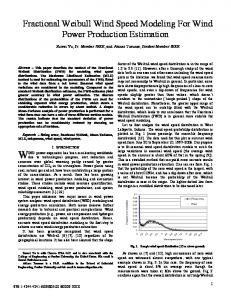
Principle of Operation The ion wind engine concept is illustrated in Figure 1. The engine consists of a pair of electrodes. The upstream electrode (anode) is grounded, and the downstream electrode (cathode) is held at a negative potential. The electrodes are placed flush with the surface of the flat plate, such that they do not protrude into the flow. For the 2D simulations presented here, the electrodes are 20 µm wide and spaced 10 µm apart. The electrodes are placed downstream of the leading edge such that the local Reynolds number, defined in the usual manner,
Uxo
e-
Figure 1 Schematic illustration of the ion wind engine, where E represents the general direction of the electric field and r f represents the general direction of the body force.
NUMERICAL MODELING
Re xo =
ionized air
(5)
The three terms on the right side of Eq. (5) represent the Coulombic force, the force due to permittivity gradient, and the electrostriction force, respectively. In general, the permittivity gradient is negligible (variation for air is less than 0.1% over a range of 1000K [24]). Additionally, electrostriction does not affect the flow field in the absence of a two-phase interface [7]. Therefore, these two terms were neglected, and the body force was simply modeled as a function of the electric field and ion charge density. Negative ions are typically electrons and, due to their low mass, have a negligible effect on the bulk flow. Additionally, Joule heating was not included in the energy equation, though it can be significant when the electrical power dissipation is sufficiently high such as during ionic breakdown [25]. However, because low applied voltages and currents are used, this effect was assumed to be negligible. Ion transport was modeled using [22]
(1)
takes a value of 340. The plate has a length L = 3 cm with ReL = 2050, such that the flow is considered laminar over the entire plate. Operation of the ion wind engine requires that a sufficiently high electrical potential difference is imposed between the electrodes, generating an electric field of the order of 10 V/µm such that electron emission occurs. The electrons collide with neutral air molecules, effectively ionizing the air, and the ions are pulled towards the cathode. The ion/neutral interactions are represented by a body force on the bulk flow leading to boundary layer disruption. Figure 1 shows the general directions of the electric field, body force and ion movement.
r r r r ∇ ⋅ σ E + bE ρ e + u ρ e = DIA∇2 ρ e
(
)
(6)
The three terms on the left side of Eq. (6) represent conduction, drift, and convection of ions due to bulk flow, respectively. The term on the right side represents the diffusion of ions through air. The drift term represents the characteristic velocity of ions:
47
r r vion = bE
The notation xi refers to the 2D directions, x and y. The nondimensionalized equations yield the following set of dimensionless parameters
(7)
Typically, the conduction term is negligible due to the extremely low electrical conductivity of air (1.61x10⁻²³ Ω-1m-1 and decreasing with temperature [26]) and was omitted in this work. The ion mobility in air is taken to be 3.0x10⁻⁴ m2/V-s (values in literature vary from 2.0-3.0 x10⁻⁴ m2/V-s [5,12,20]) and the mass diffusion coefficient is assumed to be that of O2 in air at room temperature 2.0x10⁻⁵m2/s [27]. Often, the convection term is dominated by the drift term due to high ion velocities relative to the bulk flow. However, this term was retained in this analysis. The electrostatic field is governed by the Poisson equation
r r ρ ∇ ⋅ E = −∇2Φ = e
Re ID =
*
)
(
)
r r * ED Φ ; E = ; Φ* = ; ρ = 2 ρ b Φ app Φ app Φ app r r pD 2 uD T ; θ= ; p* = 2 2 ; u * = ρ b Φ app bΦ app T∞ r x r xi* = i ; ∇* = D∇ D
k
(15)
plate surface. For the electrostatic equation, the two electrodes are modeled using Dirichlet boundaries, where the upstream anode is grounded and set at Φ* = 0 and the downstream cathode is set to an applied negative potential and nondimensionalized to Φ* = -1. The remainder of the plate is assumed to be electrically insulated, implying homogeneous Neumann boundaries. The inlet and outlet of the flow domain are also set to zero flux boundary conditions. The ion transport boundaries are more difficult to quantify. During actual operation, ions are generated in the interstitial air between the electrodes and flow through the cathode to generate a current. Based on this concept, the ion transport boundaries were modeled with fixed current fluxes at the electrodes. A positive current flux was used at the upstream electrode for ions entering the domain, and a negative flux of equal magnitude was used at the downstream electrode for ions leaving the domain to conserve charge. While this model does not capture the actual formation of ions, it does model the flow of ions within the domain and through the cathode. The remaining portion of the plate is assumed to be well insulated, and therefore, zero flux boundary conditions are used. The inlet and outlet of the flow domain were treated as Dirichlet boundaries with ρe* = 0 to
(10) (11) (12) (13)
with the non-dimensional variables: * e
υρ C p
Boundary Conditions At the domain inlet, a uniform velocity parallel to the plate and a uniform temperature were imposed. A static pressure of zero was applied at the domain outlet. Upstream of the plate, a symmetry boundary condition (consisting of zero normal gradients across the boundary for all quantities) was used to ensure well defined flow prior to the plate’s leading edge. Similarly, the far-field boundary condition was also modeled as symmetric and was placed sufficiently far from the plate based on the expected boundary layer thickness ( y * ≈ 60δ L* ). A uniform heat flux, q " , was imposed on the
(9)
r r r r r 1 ⋅ ∇* u * = −∇* p* + ∇*2u * + ρ e* E * Re ID r r 1 u * ⋅ ∇*θ = ∇*2θ Energy: Re ID Pr r * r * * r* * 1 ∇*2 ρ e* Ion Transport: ∇ ⋅ E ρ e + u ρ e = PeID r * r* ⎛ ρb ⎞ * *2 * Electrostatic: ∇ ⋅ E = −∇ Φ = ⎜ ⎟ ρe ⎝ ε ⎠
( ur
DIA
; Pr =
r
spacing) as the characteristic length rather than the length of the plate, L. Ion velocity was used rather than the bulk r velocity, u , because ion drift typically governs the transport of the ions (and thus the body force). Additionally, the length D is the spacing between the electrodes and represents the region of most interest. The non-dimensionalized governing equations may then be represented as:
r r ∇* ⋅ u * = 0
bΦ app
ρe, E and Φ gradients, and very conservative under-relaxation factors (less than 0.1) were used. In general, a non-uniform mesh was used, with increased mesh densities near the leading edge, in the boundary layer region above the plate, and in the vicinity of the electrodes.
The right side of the equation is the space charge effect and is the source of electric field screening (where the permittivity of air is ε = 8.85x10⁻¹² F/m [24]). Space charge alters the shape of the electrical field and is not negligible. The governing equations were non-dimensionalized r using vion as the characteristic velocity and D (electrode
Continuity: Momentum:
υ
; PeID =
The governing equations, Eqs. (9)-(13), were solved using the commercial CFD package, FLUENT [28]. The continuity, momentum and energy equations were solved with the built-in flow solver, whereas the ion transport and electrostatic equations were coded as generic transport equations via a macro function. Due to limitations of the solver, the five equations were solved sequentially. However, because of the space charge effect, strong coupling exists between Eq. (12) and Eq. (13) for which sequential solvers are not the optimal method, causing some degree of instability. Consequently, a fine mesh was required in regions of large
(8)
ε
bΦ app
ρe D2
(14)
48
cross-sectional area of the anode yields a conservative value for the current flux. This value was then used as the boundary condition for ion transport at the electrodes. It is entirely likely, however, that only a few carbon tips actively participate in emission, which would imply a much greater local current flux. We also note that the experiments of Peterson et al. do not precisely represent the geometry modeled here. Their work more accurately represents a point-to-plane configuration such as those studied for corona discharges by Malik et al. [10] and Rosendale et al. [11]. However, because no experimental evidence exists for electron emission in air with the electrode geometry of the ion wind engines, the results from Peterson et al. provided the best available source for this information.
ensure a well-posed problem. Figure 2 shows the solution domain with the appropriate ion transport and electrostatic boundary conditions. symmetry
∂Φ * =0 ∂nˆ ρ e* = 0
∂Φ * =0 ∂nˆ ρ e* = 0
symmetry
Φ* = 0
Φ * = −1
∂ρ =K ∂nˆ
∂ρ = −K ∂nˆ
* e
* e
RESULTS AND DISCUSSION
∂Φ * =0 ∂nˆ ∂ρ e* =0 ∂nˆ
Steady-state numerical results were obtained for a single ion engine as well as for a series of engines. Figure 3 shows velocity vectors in the immediate vicinity of the ion wind engine for both undisturbed flat plate flow and with the ion engine active. As shown in the figure, the body force generated by the ions and electric field causes considerable distortion of the near-wall velocity profile, which is the primary reason for increased heat transfer. Furthermore, because of the planar nature of the electrodes, a non-negligible y-component exists in the electric field, resulting in a downward force on the flow upstream of the cathode. Therefore, the boundary layer is driven closer to the wall, contributing additional heat transfer enhancement in a manner similar to suction. Figure 4 shows a comparison of the non-dimensional temperature contours for the ion engine in both active and inactive states. The abscissa shows the location of the ion engine relative to the length of the plate (i.e. the computational domain). The ordinate is non-dimensionalized to the thickness of the thermal boundary layer (δth) which is defined as the height at which
Figure 2 Solution domain (not to scale) with ion transport and electrostatic boundary condition (flow and heat transfer BCs omitted for clarity). The variable K represents an arbitrary constant value for the ion transport boundary. The insulated boundary for the downstream portion of the plate applies to the upstream portion and between electrodes as well.
The experimental measurements of Peterson et al. [17] provided the basis for the numerical values selected for the ion transport and electrostatic boundary conditions. Current flow was measured in [17] from an emitting cathode covered with nanostructured carbon to a collecting pin anode suspended above the cathode, separated by a gap distance of approximately 10 µm. Under an applied voltage, the cathode emitted electrons from the surface, thus ionizing the air. Their work documented current-voltage relationships for a variety of materials and electrode spacings. The potential was explicitly set experimentally and applied to this simulation in nondimensional form as discussed above. However, current fluxes (I/m2) are needed for the ion transport boundaries, whereas only current (I) data were presented by Peterson et al. Converting a known current between the cathode and anode to a current flux is not straightforward. The primary difficulty lies in estimation of the surface area of the substrate emitting electrons. Nanostructured carbon, such as diamond, contains many fine tips whose sharp features serve to enhance the local electrical field, resulting in electron field emission. The exact quantity and location of the tips that are actively emitting is not easily measured, leading to considerable uncertainty in the estimation of emitting surface area. However, the current flux can be estimated based on the collecting anode pin dimensions. The current divided by the
θ=
T = 0.99 T∞
(16)
A single value for the thermal boundary layer thickness is used for non-dimensionalization; this is the thickness for undisturbed flat plate flow at the location of the engines (i.e. plots (a) and (b) are on identical scales). An active ion engine thins the thermal boundary layer and produces the desired heat transfer enhancement at the plate. The figure also demonstrates that in addition to the increased cooling near the engine, there is both a minor upstream enhancement and, to a greater extent, a downstream enhancement.
49
y
δx
y 1.0
1.0 1.1 1.2 1.3 1.4 1.5 1.6 1.7 1.8 1.9 2.0
δth
0.03
0.02
0 y
(a)
1.0
0.01
L
(a) δx
0.10
0.16 engine (b)
0.03
x
L
0.02
Figure 4 (a) Non-dimensional temperature contours through the thermal boundary layer for undisturbed boundary-layer flow. (b) Contours at the same location and on the same scale with the ion wind engine active. The engine is located at x/L=0.16.
0.01
The heat transfer coefficient is extracted from the numerical results as
hx = 0
0.23
anode
(b)
cathode
L
q" (Twall ,x − T∞ )
(17)
where Twall,x is the local wall temperature predicted by the model assuming an infinitely thin wall and no lateral thermal conduction. In each case, the predicted heat transfer enhancement is defined as the increase in local heat transfer coefficient relative to undisturbed boundary layer flow, or
Figure 3 (a) Near-wall (y