Numerical Simulation of Pulse-Width-Modulated Micropumps with Diffuser/Nozzle Elements Nam-Trung Nguyen, Xiaoyang Huang Nanyang Technological University, School of Mechanical and Production Engineering Nanyang Avenue, 639798, Singapore,
[email protected] ABSTRACT This paper presents the numerical simulation of a new control method for dynamic micropumps with diffuser/nozzle elements: the pulse-width-modulation (PWM) of the drive signal. A piezo disk with a square wave signal actuates the pump, the square-wave-like deflection of the membrane causes velocity pulses in opposite directions. Because of the inertia of the fluid in the pump chamber, the time distance between these velocity pulses controls the generated flow rate. The paper compares results of models with different boundary conditions of the pump membrane: time-dependent velocity and time-dependent deflection. This paper also describes the fabrication of pump prototype based on laser micromachining. Simulation results are then compared to experimental results.
their flow rates by varying the drive frequency. A voltage converter provides a constant high voltage. The actuatorÕs drive voltage is switched on and off by the control signal. In modern digital control systems, the control signal is provided directly by a micro controller or a digital signal processor and therefore has a typical square wave shape. Using the micro controller technology, itÕs simple to implement a pulse width modulated signal for control purpose. The control system doesnÕt need the inaccurate and complicated high-voltage amplifier based on analog technique. The drive voltage causes a square-wave-like deflection of the membrane, which in turn generates velocity pulses in opposite directions. Because of the inertia of the fluid in the pump chamber, the time distance between these velocity pulses (or the pulse width of the drive signal) controls the generated flow rate.
Keywords: Microfluidics, micro pump, pulse width modulation, computational fluid dynamics.
1
INTRODUCTION
Design, fabrication and characterization of microfluidic devices have been emerging as important research topics of the microsystem technology. Micropumps are significant components for delivering fluid and samples in microanalysis system. Micromachined pumps are classified by actuating principles (piezoelectric, pneumatic, thermopneumatic, thermomechanic, electrostatic) or pump principles (reciprocating, peristaltic, electrohydrodynamic, electroosmotic, ultrasonic) [1, 2, 3]. Most of the reported pumps are based on the use of passive valves or fluidic diodes (diffuser/nozzle element, valvular conduits). The latter have the advantage of simple fabrication. Simulations carried out for these pumps are mostly based on dynamic macro models using analogy to electric circuits [4] or static diffuser/nozzle model [5]. In all reported works, the frequency or the amplitude of the drive signal controls the pump performance. This paper presents the complex threedimensional transient simulation of a new control method for dynamic micropumps with diffuser/nozzle elements: the pulse-width-modulation (PWM) of drive signals. Most micro pumps use piezo disk as actuator. Because of the high voltage needed for the piezo disk, the design of a miniaturized high-voltage analog amplifier is very difficult. The most of published micro pumps let control
Diffuser/nozzle
Pump membrane Outlet L=2,4mm R=5mm
z Inlet
x y
Pumping direction
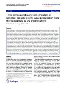
Figure1: Pump model for numerical investigation Fig.1 illustrates the investigated pump model. Only the marked volume is considered in order to reduce the calculation time. The transient simulation was carried out for water and a pump frequency of 100 Hz. The pulse width ratio w/T (Fig. 4a) varies between 0 and 1. Two models with different boundary conditions are used for analysis with ANSYS-FLOTRAN and CFD-ACE+: • Time-dependent velocity: In this case, the maximum membrane deflection is kept small relatively to the pump chamber height in order to minimize the influence of the variation of the pump chamber. Because of the
small membrane deflection compared to the chamber height (1:1000), the analysis with FLOTRAN was achieved by assuming that there is no membrane deflection. Only the velocity of the membrane was given as the boundary condition. • Time-dependent membrane deflection: The timedependent deflection of the pump membrane is described by moving wall and moving grid conditions. The membrane shape is recalculated in each time step. In both cases, the interaction between the structure analysis and fluid analysis is neglected. And therefore the model neglects the frequency dependency of the amplitude of the membrane deflection by a given drive voltage. The pressure at the inlet and outlet are equal. A simple analytical model formulates the transient membrane deflection for the second case.
pulse width ratio generated by a frequency f=100 Hz and a maximum membrane velocity of 0,2 mm/s (corresponding to a maximum deflection of 0.25 micron) is shown in Fig. 5. The results show that the flow rate can be generated from zero to a maximum value by using the variable pulse width. The drive voltage and its frequency determine the maximum flow rate. Velocity profile at inlet
0.01 0.005 0 -0.005 -0.01 -0.015 10
2
NUMERICAL MODEL
8 x 10
-3
6 4
Time
2.1
2
-2
-1
1
0
3
2
x 10
-4
Channel height direction (m)
Time-dependent velocity
Since the ANSYS-FLOTRAN package offers limited capability of boundary conditions. The displacement of the pump membrane is neglected. The transient velocity is applied on the pump membrane as the boundary condition. This model assumes equal velocity values over the pump membrane. The software allows either step change or ramp change of the boundary conditions. The later is chosen because the periodic function of membrane velocity needs to be as ÒsmoothÓ as possible. The model automatically approximates the values of sub-steps between the given time steps (circles in Fig. 2). Step change
1
4
x 10-7 T
2 w
a)
0 0 x 10 -4 2
10 Ramp change
0.02Time (s) 0.03
0.04
0.05
0.06
0.01
0.02 Time (s)0.03
0.04
0.05
0.06
0.01
0.02 Time (s)0.03
0.04
0.05
0.06
0 w
-2 b) 0 0.1
-0.1 c) 0
5
0.01
0
0 -1 0 a) 1
Figure 3: Velocity profiles at the outlet versus time with a pulse ration of w/T=0.375 and a pump frequency of 100Hz
15
20
0
Figure 4: Time signals: a) The membrane deflection b) The membrane velocity, c) The maximum velocity at the inlet for different pulse width ratios: w/T=0.375 (solid line, o), w/T=0,5 (dashed line, x) and w/T=0,875 (dotted line, +) 1
-1 0 b)
5
10
15
x 10
-3
20
Time
Figure2: Transient boundary conditions for the membrane velocity: a) Step change, b) Ramp change. The transient values are modified externally by setting the velocity condition and by using results of the last time step as the initial condition for the current analysis. Fig. 3 illustrates the typical results of the first-order velocity profile. Fig. 4 shows the typical transient values of the membrane displacement (Fig. 4a) and membrane velocity (Fig. 4b). The maximum velocities at pump inlet for different pulse widths are shown in Fig. 3c. The flow rate versus the
0.8
0.6
0.4
0.2
0 0
0.2
0.4
0.6
Pulse width ratio w/T
0.8
1
Figure 5: Flow rate versus pulse width ratio w/T.
2.2
Time-dependent membrane deflection
Based on the moving wall and moving grid capabilities of CFD-ACE+, the small deflection of the sensor membrane is described as a function of coordinates x, y and time t as following [6]: 2
x2 + y2 √ dz ( x, y, t ) = Ao (t ) 1 − √ R ↵
2
,
(1)
where A0(t) is the deflection at the membrane center, R is the membrane radius (Fig. 1). A0(t) is a square wave function with a pulse width w: Ao ,max 0 ≤ (t mod T ) < w (2) Ao (t ) = − Ao ,max w ≤ (t mod T ) < T T=1/f is the time period of the drive signal and A0,max is the maximum deflection amplitude. Using the Fourier series, the square wave function can also be approximated as: × C 2nπt with n=1,2,3É (3) Ao (t ) = 0 + C n cos √ T 2 ↵ n =1 and the coefficients: w (4) C 0 = 2 Amax ? T nπw 2 Amax sin( ) T (5) Cn = nπ Based on Eq. 3, the velocity and the acceleration of the membrane center can be described for a model with timedependent velocity as: × 2nπt with n=1,2,3É (6) 2C n nπ ′ − sin v 0 (t ) = A0 (t ) = √ T T ↵ n =1 × 4C n n 2 π 2 2 nπt with n=1,2,3É (7) '′ √ a (t ) = A0 (t ) = cos − T √ T2 n =1 ↵ The grid position of the model is updated in each time step by using a user routine written in FOTRAN [7], [8]. Fig. 6 shows the typical deformed grids of a simplified model (with limited element numbers) in supply mode (Fig. 6a) and pump mode (Fig. 6b), the scaling factor for the zaxis is 6.
With 56250 grid elements and 50 time steps, the calculation in a Windows NT environment and Pentium II PC (200 MHz, 128 Mbytes RAM) takes about 20 hours. The fine grids are necessary for a higher accuracy because the time-dependent flow rate is about 100 times larger than the time-averaged flow rate. Since the net flow rate is a time-averaged value, the convergence of the simulation is reached if the timeaveraged value of the inlet flow rate is equal the one of the outlet. The best results for the above mentioned model were obtained with 20 time steps for 1 pumping period and 230 iterations for 1 time step.
a) z y
b)
Figure 7: Velocity field in the micro pump(perspective).
a)
y x b)
Figure 8: Velocity field in the micro pump (top view).
3
z a)
y
x b)
Figure 6: Deformed grids in supply mode and pump mode. Fig. 7a and Fig.8a show the velocity fields of the micro pump in supply mode. Fig. 7b and Fig. 8b illustrate the same field in pump mode.
x
PUMP PROTOTYPE FABRICATION
In the most recently reported paper, micro pumps are made of silicon. The big advantages of silicon based micro pumps are their compatibility with microelectronics and the ability of batch fabrications. One of the unsolved drawbacks is the complicated and non-standardized packaging technology. For small-scale production, the batch fabrication can not compensate the cost of expensive and time-consuming mask technologies. Direct laser writing is a flexible and effective tool with low operating cost [9]. The resolution of the laser micromachining process depends on the laser wavelength, the focus length and the aberration of the lens system. The carving depth mainly
l/min] φ
of the transient flow sensor signal and the control algorithm for the PWM control system.
[µ Flow rate
30 20 10 80 0 60
e Fr
200
qu
40
300
en cy
20
400
]f
z [H
depends on the focus length and depth of focus of the optical system [10]. Our pump prototype is made of copper. Using a continuously pumped Nd:YAG laser, structures with maximum depth of 500 microns and a minimum trench size of 50 microns can be fabricated. The pump geometry is designed in a CAD-program and transferred to the stage control system of the laser beam. Based on geometry information from the CAD-file the laser beam structures the pump into the copper plate. The actuator is a brass disk with piezo ceramic layer glued on it. The piezo disk is commercially available as a buzzer. The cover plate fixes the piezo disk with the copper plate. Silicon rubber fills the cap between the two plates and seals the pump chamber as well as the diffuser/ nozzle structure, Fig. 9.
500
3
lse
th wid
]w
[%
Pu
0
Figure 10: Flow rate versus pulse width ratio [11]
REFERENCES 2
1
Figure 9: The micropump:1) copper plate with carved pump structure, 2) piezo disk, 3) cover plate with inlet and outlet.
4
CONCLUSION
This paper present the numerical simulation of the pulse width modulation mode of a micropump. The simulation was carried out with two different CFD-tools: ANSYSFLOTRAN and CFD-ACE. While ANSYS-FLOTRAN only allows simplified model with neglected membrane deflection, CFD-ACE allows building a complex model with moving wall and moving grid conditions. Simulations result show that using the PWM, the flow rate can be adjust from 0 to a maximum value. The flow range is determined by this maximum value and its corresponding drive frequency as well the drive voltage. Experiment results achieved in a former project [11] verified this theory, Fig. 10. Simulation results show that this control method can be implemented in microfluidic systems with valveless (dynamic) pumps. Future works will concentrate on the verification of simulation models on prototype pumps, the integration of a flow sensor onto the pump, the evaluation
[1] S. Shoji, M. Esashi, ÒMicroflow Devices and SystemsÓ, J. Micromech. Microeng. 4, 157, 1994. [2] P. Gravesen, J. Branebjerg, O. S. Jensen, ÒMicrofluidics -a ReviewÓ, J. Micromech. Microeng. 3, pp. 168-182, 1993. [3] M. Elwenspoek, T.S. Lammerink, R. Miyake and J. H. J. Fluitman, ÒTowards Integrated Microliquid Handling SystemsÓ, J. Micromech. Microeng. 4, 227, 1994. [4] A. Olsson, G. Stemme, E. Stemme, ÒThe valveless difusser pump Ð a numerical design study using MATLABÓ, Proc. Int. Conf. Modeling and Simulation of Microsystems MSM99, 1999. [5] A. Olsson, G. Stemme, E. Stemme, ÒNumerical of flatwalled diffuser elements for valveless micropumpsÓ, Proc. Int. Conf. Modeling and Simulation of Microsystems MSM99, 1999. [6] Timoshenko, Woinosky-Krieger, ÒTheory of plates and shellsÓ, McGraw-Hill, 3. Edition, 1959. [7] N. T. Nguyen, R. Doering, A. Lal, and R. M. White, ÒComputational Fluid Dynamics Modeling of Flexural Plate Wave PumpsÓ, 1998 IEEE International Ultrasonic Symposium, Sendai, Japan,Vol 1., 431, 1998. [8] N. T. Nguyen, R. M. White, ÒDesign and optimization of an ultrasonic flexural plate wave micro pump using numerical simulationÓ, Sensors and Actuators A ,Volume 77/3, Elsevier, , 231, 1999. [9] M. Muellenborn, H. Dirac, J. Peterson, S. Bowstra, ÒFast three-dimensional laser micromachining of silicon for microsystemsÓ, Sensors and Actuators A, Volume 61, 121, 1996. [10] S. Dauer, A. Ehlert, S. Buettgenbach, ÒRapid prototyping of micromechanical devices using a Q-switched Nd:YAG laser with optional frequency doublingÓ, Sensors and Actuators A, Volume 76, 381, 1999. [11] N. T. Nguyen, S. Schubert, S. Richter, W. Dštzel: ÒHybrid-assembled micro dosing system using silicon-based micropump/valve and mass flow sensorÓ, Sensors and Actuators A, Volume 69, Elsevier, 85, 1998.