EUROSTEEL 2014, September 10-12, 2014, Naples, Italy
NUMERICAL VALIDATION OF THE GENERAL METHOD FOR STRUCTURAL FIRE DESIGN OF WEB-TAPERED BEAMS Carlos Coutoa, Paulo Vila Reala, João Ferreiraa, Nuno Lopesa a
LABEST, Civil Engineering Department, University of Aveiro, Portugal
[email protected],
[email protected],
[email protected],
[email protected]
INTRODUCTION Tapered members are commonly used in steel constructions such as portal frames, towers, and architectural exposed steel columns and beams in large buildings, however, design methods are not yet consolidated. Due to the non-uniform cross-section along the member length, the corresponding flexural, axial and torsional stiffness varies making the stability analysis of tapered members much more complicated than that of uniform members. Also, clauses 6.3.1 to 6.3.3 of Part 1-1 of Eurocode 3 [1] regarding the stability check of steel members at normal temperature do not apply due to variation of the stiffness along the member. Therefore, the verification of the resistance should be performed with a cross-sectional verification based on second-order internal forces and by using the General Method as given in clause 6.3.4 of Part 1-1 of Eurocode 3 (EC3-1-1). The General Method consists on a Merchant-Rankine type of empirical interaction expression to uncouple the in-plane effects and the out-of-plane effects. Despite the interesting approach provided by this method, it is not widely validated [2] and few studies exist regarding its safety and accuracy [3, 4]. For the design in fire situation, no specific rules exists in the Part 1.2 of Eurocode 3 (EC3-12) [5] for web-tapered members and it is not clear that the General Method can be applied to these cases, since there are no studies on this field known to the authors. For uniform members submitted to compression or bending, the adaption and application of the General Method to elevated temperatures leads to the same expressions as defined in Clauses 4.2.3.2 and 4.2.3.3 of EN 1993-1-2. This paper presents a numerical validation of the General Method included in the Part 1.1 of the Eurocode 3 [1] adapted for the fire design of web-tapered beams, allowing for the assessment of their resistance to lateral torsional buckling. The in-plane and out-of-plane behaviour of single members is analysed using a FEM software [6, 7] with shell elements for a materially nonlinear analysis with imperfections included (GMNIA) to assess the ultimate load bearing resistance of the members at elevated temperatures. The obtained results are then compared with the results of the application of the General Method with the necessary allowances to account for the temperature effects in reducing the strength and stiffness of the elements. A parametric study is carried out for non-uniform members at elevated temperatures considering different cross-sectional geometries, member span, and lateral restraints. 1
THE GENERAL METHOD
According to the EN 1993-1-1, the global stability analysis of irregular structural members, like for example tapered columns, beams or beam-columns, built-up or not, with complex support conditions or not, may be performed by using the general method. In this section of the paper, more than explain the fundaments of the General Method, it is intended to illustrate its adaptation to be used in fire situation. 1.1 The General Method at normal temperature The General method allows for the verification of the resistance to lateral and lateral torsional buckling of structural components, i.e., the out-of-plane buckling, by ensuring that:
χ opα ult ,k ≥ 1. 0 γ M1
(1)
where α ult ,k is the minimum load amplifier of the design loads to reach the characteristic resistance of the most critical cross-section of the structural component considering its in-plane behaviour without taking lateral or lateral torsional buckling into account, however accounting for all effects due to in-plane geometrical deformation and imperfections, global and local, where relevant. For the case of a beam, with in-plane loading, M y , Rk is the characteristic value of resistance moment at the most critical cross-section. α ult ,k =
M y ,Rk M y ,Ed
(2)
is the reduction factor for the non-dimensional slenderness λop (see Eq. (3)), to take account of lateral and lateral torsional buckling; M y ,Ed is the design value of the in-plane moment acting on the element at the most critical crosssection. The global non dimensional slenderness, λop , for the structural component should be determined from χ op
λop =
α ult , k α cr ,op
(3)
where α ult ,k is defined in Eq. (2); α cr ,op is the minimum amplifier for the in-plane design loads to reach the elastic critical resistance of the structural component with regards to lateral or lateral torsional buckling without accounting for in-plane flexural buckling.
According to the Eurocode 3, the reduction factor χ op may be determined using the values of the reduction factor for flexural buckling χ and the reduction factor for lateral torsional buckling χ LT , each one calculated for the global non dimensional slenderness λop and considering the appropriated buckling curve. In the case of non-uniform elements, the selection of the appropriate buckling curve is an additional problem. In fire situation, the buckling curves for both flexural and lateral torsional buckling do not depend on the dimensions of the cross-section (see Eq. (11) for the case of lateral torsional buckling).
1.2 The General Method at elevated temperature An adaptation of the General Method for checking the fire resistance of unrestrained beams will be shown in this section. In case of fire the yield strength, f y ,θ and the Young modulus, E θ , are defined as: f y ,θ = k y ,θ f y
(4)
and E θ = k E ,θ E
(5)
where k y ,θ and k E ,θ are respectively the reductions factors for the yield strength and the Young Modulus at temperature θ and f y and E are the yield strength and the Young Modulus at normal temperature. As the load amplifier is directly proportional to the yield strength and the critical amplifier is directly proportional to the Young Modulus, in fire situation the following expressions can be written: α ult ,θ ,k = k y ,θ α ult , k
(6)
and α cr ,θ ,op = k E ,θ α cr ,op
(7)
Substituting Eq. (6) and Eq. (7) in Eq. (3), the global non dimensional slenderness is given, at elevated temperature, by
λop ,θ =
α ult ,θ, k α cr ,θ,op
=
k y ,θα ult ,k
= λop
k E ,θ α cr ,op
k y ,θ k E ,θ
(8)
From EN 1993-1-2, the reduction factor for lateral-torsional buckling in the fire design situation is given by:
χ LT ,fi =
1 φ LT ,θ + [φLT ,θ ]2 − [λ LT ,θ ]2
(9)
with φ LT ,θ =
[
1 1 + α λ LT ,θ + ( λ LT ,θ ) 2 2
]
(10)
In Eq. (9) and Eq. (10), the non dimensional slenderness for lateral torsional buckling, λ LT ,θ , should be substituted by the global non dimensional slenderness given by Eq. (8). The imperfection factor α , is given by: α = 0.65 235 / f y
(11)
Knowing χ op ,fi = χ LT ,fi , the verification can be done using Eq. (1) adapted for fire situation:
χ op ,fi α ult ,θ,k γ M ,fi
2
≥ 1.0
(12)
NUMERICAL STUDY
A numeric investigation on the behavior of non-uniform beams submitted triangular bending diagram was performed with the finite element method using the software SAFIR [6] at room temperature and in case of fire, considering material and geometric imperfections as well as different cross-sections, span lengths and temperatures (20ºC, 350ºC, 450ºC, 550ºC and 700ºC).
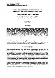
2.1 Numeric model The beams were discretized using shell finite elements. In SAFIR, the shell finite element has four nodes with six degrees of freedom (3 translations and 3 rotations) each and adopt the Kirchoff’s theory formulation with a total co-rotational description. The material law is a two-dimensional constitutive relation with the von Mises yield surface. The integration on the shell element follows a Gauss scheme with 2 × 2 points on the surface and 3 points through the thickness. The shell finite element used in SAFIR and its ability to model local buckling has been validated by Talamona and Franssen [8]. A mesh with 10 shell elements for the flange, 22 shell elements for the web and 100 shell elements along the width has been used. The loads were applied to the model by means of nodal forces. “Fork-support” conditions have been considered in the model by restraining vertical displacements of the bottom flange and the out-of-the plane horizontal displacements of the web in the extremities of the beam as well as the rotation about the beam axis being the warping free. When considered, lateral restraints were introduced by restraining the lateral displacements of the web nodes. Geometric imperfections have been introduced in the model by changing the node coordinates to represent the worst scenario for the assessment of beam resistance. This has been considered as the shape given by the eigenmodes of a linear buckling analysis (LBA) performed with the software Cast3M [7]. A tool was written in order to automate this process and resulted in the software RUBY [9]. In accordance with the finite element method of analysis recommendations given in the Annex C of EN1993-1-5 [10], a combination of global and local modes (see Fig. 1) has been used, where the lower mode has been taken as the leading imperfection and the other one reduced to 70%. The amplitude of the imperfections has been chosen as 80% of the fabrication tolerances given in the EN1090-2+A1 [11], as suggested in the same annex. Consequently, the global mode has been scaled to 80% of L/750 and the local mode has been scaled either to 80% of b/100 if the maximum node displacement (in respect to the local mode) occurs in the flange and to 80% of hw/100 if the maximum node displacement occurs in the web. In the previous formulas, b is the flange width and hw is the height of the web of the cross-section. 0.15b fy T C
C
0.25 fy
0.25b 0.125hw
0.075hw
T fy
h
0.25 fy C
T b
a)
b)
c)
Fig. 1. Buckling modes in a laterally unrestrained steel beam with tapered web subjected to bending moment in the major-section. a) Example of a global (LTB) eigenmode, b) local eigenmode c) residual stresses for welded profiles (taken from [12]).
2.2 Case studies Beams with different cross-sections, taper ratios, member lengths, temperatures and lateral restraint conditions have been considered according to Table 1. A triangular bending diagram was applied (ψ=0). In Table 1, hw1, hw2 are the minimum and maximum web height respectively, tw is the thickness of the web and b is the flange width and tf the flange thickness. The lateral restraint conditions that have been considered are i) only at the supports, ii) at the supports and at the middle of the beam iii) at the supports and plus 2 lateral restraints equally spaced.
Table 1.
Summary of the cases run on the numerical study.
Cross-section aligned at the top (hw1-hw2) x tw + b x tf
Temperature θa (ºC)
Member length L (m)
(400-1000)x22+300x30
2.5, 3, 3.5, 4, 4.5, 5, 5.5, 6, 7, 9, 11, 15 2.5, 3, 3.5, 4, 4.5, 5, 5.5, 6 3, 5, 7, 10, 15
(280-480)x10+250x20
3, 6, 9, 12, 15
(296-396)x8+150x15
6, 9, 12, 15
(400-1000)x22+300x30
6, 9, 12, 15
(280-480)x10+250x20
3, 6, 9, 12, 15
(296-396)x8+150x15
3, 6, 9, 12, 15
(280-480)x10+250x20 (296-396)x8+150x15
(400-1000)x22+300x30
Lateral restraints Bending diagram
ψM1
20, 350, 450, 550, 700
L
M1 L/2
ψ=0
L/2
(moment applied in the major section)
L L/3
L/3
9, 12, 15
L/3
L
2.3 Comparison with General Method In this section, a comparison of the results obtained with SAFIR and with the General Method is done. In Fig. 2 it is depicted the design curve obtained by using Eq. (10) and (11) and considering χ op ,fi = χ LT ,fi and compared with numerical results. The points on the figures are calculated according to
χ op , fi =
M SAFIR M y , fi , Rk
(15)
where M SAFIR is the bending moment at the collapse of the beam obtained in SAFIR and M y , fi ,Rk is the cross-sectional bending resistance about the major-axis of the critical cross-section, in this case, since the bending diagram is triangular (ψ=0, see Table 1) it corresponds to the section where the bending moment is applied. 1.2
1.2
EN1993-1-2
1
EN1993-1-2
1
350ºC 450ºC 550ºC 700ºC
350ºC 450ºC
0.8
550ºC
chi,op,fi
chi,op,fi
0.8
700ºC
0.6 0.4
0.4
0.2
0.2 0
0 0
a)
0.6
0.25
0.5
0.75
1
1.25 1.5 lambda,op,theta
1.75
2
2.25
0
2.5
0.25
0.5
0.75
1
b)
1.25 1.5 lambda,op,theta
1.75
2
2.25
2.5
1.2 EN1993-1-2
1
350ºC 450ºC
0.8 chi,op,fi
550ºC 700ºC
0.6
0.4
0.2
0 0
c)
0.25
0.5
0.75
1
1.25 1.5 lambda,op,theta
1.75
2
2.25
2.5
Fig. 2. Comparison between numerical results of SAFIR and the General Method at elevated temperatures a) without lateral restraints along the member, b) one lateral restraint in the middle b) two lateral restraints equally spaced.
The results depicted in Fig. 2 show that there is good agreement between the numerical results and the simple design methods using the General Method at elevated temperatures.
3
CONCLUSIONS
In this paper, a first approach to understand the safety and accuracy of the General Method to be used in the design of web tapered steel beams in case of fire was done. It was demonstrated that the adaptation of the General Method to account for the effects of temperature in the reduction of the strength and stiffness of the steel is very straightforward for elements in bending. On the basis of a numerical study considering different temperatures, taper-ratios, cross-sections, member-lengths and lateral restraint conditions was possible to perceive that the General Method may be a valid approach for the design of web-tapered steel beams at elevated temperatures. Despite the promising results obtained in this study, it should be noted that more studies should be performed on this subject to validate the use of the General Method at elevated temperatures.
ACKNOWLEDGEMENTS The work in this paper was supported by the Fundação para a Ciência e Tecnologia project PTDC/ECM-EST/1970/2012, TAPERSTEEL - Stability design of non-uniform steel members and by the European Commission, Research Fund for Coal and Steel in the frame of the research project “FIDESC4 - Fire Design of Steel Members with Welded or Hot-rolled Class 4 Cross-sections”, Grant Agreement Number RFSR-CT-2011-00030.
REFERENCES [1] CEN, “EN 1993-1-1, Eurocode 3: Design of steel structures - Part 1-1: General rules and rules for buildings.” European Committee for Standardisation, Brussels, 2005. [2] Simões da Silva L., R. Simões, H. Gervásio, Design of steel structures Eurocode 3: design of steel structures; part 1-1: general rules and rules for buildings. Berlin: Ernst, 2010. [3] Simões da Silva L., L. Marques, C. Rebelo, “Numerical validation of the general method in EC3-1-1 for prismatic members,” J. Constr. Steel Res., vol. 66, no. 4, pp. 575–590, Apr. 2010. [4] Bureau A., “Résistance au flambement et au déversement d’un poteau à intertie variable selon l'EN 1993-1-1,” Rev. Constr. Métallique, no3, CTICM, vol. 3, 2007. [5] CEN, “EN 1993-1-2, Eurocode 3: Design of steel structures - Part 1-2: General rules - Structural fire design.” European Committee for Standardisation, Brussels, 2005. [6] Franssen J.-M., “SAFIR, A Thermal/Structural Program Modelling Structures under Fire,” Eng. Journal, A.I.S.C., vol. 42, no. 3, pp. 143–158, 2005. [7] CEA, “CAST 3M is a research FEM environment; its development is sponsored by the French Atomic Energy Commission .,” 2012. [8] Talamona D., J.-M. Franssen, “A Quadrangular Shell Finite Element for Concrete and Steel Structures Subjected to Fire,” J. Fire Prot. Eng., vol. 15, no. 4, pp. 237–264, Nov. 2005. [9] Couto C., P. Vila Real, N. Lopes, “RUBY - an interface software for running a buckling analysis of SAFIR models using Cast3M.” University of Aveiro, 2013. [10] CEN, “EN 1993-1-5, Eurocode 3 - Design of steel structures - Part 1-5: Plated structural elements.” European Committee for Standardisation, Brussels, pp. 1–53, 2006. [11] CEN, “EN 1090-2+A1: Execution of steel structures and aluminium structures - Part 2 : Technical requirements for steel structures.” European Committee for Standardisation, Brussels, 2008. [12] ECCS, Ultimate limit state calculation of sway frames with rigid joints. Publication No. 33. European Convention for Constructional Steelwork Technical Committee No. 8, 1984.
EUROSTEEL 2014, September 10-12, 2014, Naples, Italy
NUMERICAL VALIDATION OF THE GENERAL METHOD FOR STRUCTURAL FIRE DESIGN OF WEB-TAPERED BEAMS Carlos Coutoa, Paulo Vila Reala, João Ferreiraa, Nuno Lopesa a
LABEST, Civil Engineering Department, University of Aveiro, Portugal
[email protected],
[email protected],
[email protected],
[email protected]
KEYWORDS: Fire, temperature, General Method, web-tapered, non-uniform members INTRODUCTION Tapered members are commonly used in steel constructions such as portal frames, towers, and architectural exposed steel columns and beams in large buildings, however, design methods are not yet consolidated. Due to the non-uniform cross-section along the member length, the corresponding flexural, axial and torsional stiffness varies making the stability analysis of tapered members much more complicated than that of uniform members. Also, clauses 6.3.1 to 6.3.3 of Part 1-1 of Eurocode 3 [1] regarding the stability check of steel members at normal temperature do not apply due to variation of the stiffness along the member. Therefore, the verification of the resistance should be performed with a cross-sectional verification based on second-order internal forces and by using the General Method as given in clause 6.3.4 of Part 1-1 of Eurocode 3 (EC3-1-1). The General Method consists on a Merchant-Rankine type of empirical interaction expression to uncouple the in-plane effects and the out-of-plane effects. Despite the interesting approach provided by this method, it is not widely validated [2] and few studies exist regarding its safety and accuracy [3, 4]. For the design in fire situation, no specific rules exists in the Part 1.2 of Eurocode 3 (EC3-12) [5] for web-tapered members and it is not clear that the General Method can be applied to these cases, since there are no studies on this field known to the authors. For uniform members submitted to compression or bending, the adaption and application of the General Method to elevated temperatures leads to the same expressions as defined in Clauses 4.2.3.2 and 4.2.3.3 of EN 1993-1-2. This paper presents a numerical validation of the General Method included in the Part 1.1 of the Eurocode 3 [1] adapted for the fire design of web-tapered beams, allowing for the assessment of their resistance to lateral torsional buckling. The in-plane and out-of-plane behaviour of single members is analysed using a FEM software [6, 7] with shell elements for a materially nonlinear analysis with imperfections included (GMNIA) to assess the ultimate load bearing resistance of the members at elevated temperatures. The obtained results are then compared with the results of the application of the General Method with the necessary allowances to account for the temperature effects in reducing the strength and stiffness of the elements. A parametric study is carried out for non-uniform members at elevated temperatures considering different cross-sectional geometries, member span, and lateral restraints. The results obtained are shown in Fig. 1. 1.2
1.2 EN1993-1-2
1
450ºC 700ºC
0.6
700ºC
0.6
0.4
0.4
0.2
0.2
0
0 0
a)
450ºC 550ºC
0.8
550ºC chi,op,fi
chi,op,fi
0.8
EN1993-1-2 350ºC
1
350ºC
0.25
0.5
0.75
1
1.25 1.5 lambda,op,theta
1.75
2
2.25
2.5
0
b)
0.25
0.5
0.75
1
1.25 1.5 lambda,op,theta
1.75
2
2.25
2.5
1.2 EN1993-1-2
1
350ºC 450ºC
0.8 chi,op,fi
550ºC 700ºC
0.6
0.4
0.2
0 0
c)
0.25
0.5
0.75
1
1.25 1.5 lambda,op,theta
1.75
2
2.25
2.5
Fig. 1. Comparison between numerical results of SAFIR and the General Method at elevated temperatures a) without lateral restraints along the member, b) one lateral restraint in the middle b) two lateral restraints equally spaced.
The results depicted in Fig. 1 show that there is good agreement between the numerical results and the simple design methods using the General Method at elevated temperatures. CONCLUSIONS In this paper, a first approach to understand the safety and accuracy of the General Method to be used in the design of web tapered steel beams in case of fire was done. It is demonstrated that the adaptation of the General Method to account for the effects of temperature in the reduction of the strength and stiffness of the steel is very straightforward for elements in bending. On the basis of a numerical study considering different temperatures, taper-ratios, cross-sections, member-lengths and lateral restraint conditions is possible to perceive that the General Method may be a valid approach for the design of web-tapered steel beams at elevated temperatures. Despite the promising results obtained in this study, it should be noted that more studies should be performed on this subject to validate the use of the General Method at elevated temperatures. ACKNOWLEDGEMENTS The work in this paper was supported by the Fundação para a Ciência e Tecnologia project PTDC/ECM-EST/1970/2012, TAPERSTEEL - Stability design of non-uniform steel members and by the European Commission, Research Fund for Coal and Steel in the frame of the research project “FIDESC4 - Fire Design of Steel Members with Welded or Hot-rolled Class 4 Cross-sections”, Grant Agreement Number RFSR-CT-2011-00030. REFERENCES [1] CEN, “EN 1993-1-1, Eurocode 3: Design of steel structures - Part 1-1: General rules and rules for buildings.” European Committee for Standardisation, Brussels, 2005. [2] Simões da Silva L., R. Simões, H. Gervásio, Design of steel structures Eurocode 3: design of steel structures; part 1-1: general rules and rules for buildings. Berlin: Ernst, 2010. [3] Simões da Silva L., L. Marques, C. Rebelo, “Numerical validation of the general method in EC3-1-1 for prismatic members,” J. Constr. Steel Res., vol. 66, no. 4, pp. 575–590, Apr. 2010. [4] Bureau A., “Résistance au flambement et au déversement d’un poteau à intertie variable selon l'EN 1993-1-1,” Rev. Constr. Métallique, no3, CTICM, vol. 3, 2007. [5] CEN, “EN 1993-1-2, Eurocode 3: Design of steel structures - Part 1-2: General rules - Structural fire design.” European Committee for Standardisation, Brussels, 2005. [6] Franssen J.-M., “SAFIR, A Thermal/Structural Program Modelling Structures under Fire,” Eng. Journal, A.I.S.C., vol. 42, no. 3, pp. 143–158, 2005. [7] CEA, “CAST 3M is a research FEM environment; its development is sponsored by the French Atomic Energy Commission .,” 2012.