1296
IEEE JOURNAL OF SELECTED TOPICS IN APPLIED EARTH OBSERVATIONS AND REMOTE SENSING, VOL. 5, NO. 4, AUGUST 2012
Object-Based Shadow Extraction and Correction of High-Resolution Optical Satellite Images Wen Liu, Student Member, IEEE, and Fumio Yamazaki, Member, IEEE
Abstract—Shadows in remote sensing images often cause problems, especially in land-cover classification and change detection. Hence, it is very useful if the radiance of shadow areas is corrected to the same level as that of shadow-free areas. In this study, a radiance measurement was carried out to investigate the spectral characteristics of sunlight. Then a method is proposed for shadow detection and correction of optical imagery. First, building shadow areas are detected using an object-based classification method that employs brightness values and their relationship with the neighboring area. Next, the detected shadow areas are corrected using a linear function to produce a shadow-free image. The shadow pixels with different darkness levels are corrected by using different ratios to obtain a smoothly restored image. The proposed semi-automated method was applied to a QuickBird and a WorldView-2 images of Tokyo, Japan, to demonstrate the effectiveness of the method. Index Terms—Image enhancement, image segmentation, object detection, optical image processing, radiometry.
I. INTRODUCTION
T
HE advent of new optical satellite sensors such as Ikonos, QuickBird, GeoEye, and WorldView has enabled us to obtain high-resolution images of the Earth’s surface. These highresolution images, however, cannot be used very effectively if they contain shadows. For example, land-cover classification cannot be applied to shadow areas because information related to the ground surface is lost in the shadows. The presence of shadows can also lead to misleading results if change detection is applied to a ground surface because of changes in the shadows, depending on the time and season. However, owing to the high dynamic range of recent optical sensors, surface information can now be collected even in cast shadows and a shadow-free image can be obtained. Several researches have been carried out on the detection of shadow areas in satellite and aerial optical images. Shadow detection methods have been developed that can be categorized into two groups. The first group includes methods that involve the detection of shadow areas using brightness information such as the digital number (DN). Most of these methods select threshold values from the histogram to distinguish shadow areas from non-shadow areas. These methods have been widely applied to aerial photographs [1], SPOT images [2], Manuscript received November 16, 2011; revised February 03, 2012; accepted February 16, 2012. Date of publication April 05, 2012; date of current version July 20, 2012. The authors are with the Department of Urban Environment Systems, Chiba University, Chiba 265-8522 Japan (e-mail:
[email protected];
[email protected]). Color versions of one or more of the figures in this paper are available online at http://ieeexplore.ieee.org. Digital Object Identifier 10.1109/JSTARS.2012.2189558
and high-resolution satellite images obtained from sensors such as Ikonos [3] and QuickBird (QB) [4]. Sarabandi et al. [5] also proposed a shadow detection method that employs the transformation of images on the basis of color invariant indices. The second group includes methods that detect shadow areas by combining 3D information and sunshine models [6], [7]. Although these methods can extract shadow areas correctly, their application is limited to cases for which 3D information is available. Much current research is focused on the correction of shadows cast by clouds in medium-resolution satellite images. The ground surface beneath clouds and their cast shadows are replaced by other information. Song and Civco [8] used a knowledge-based approach to reduce the effects of clouds by replacing a shadow area with a shadow-free area in a Landsat TM image. Kouchi and Yamazaki [9] replaced a shadow pixel caused by clouds in a Terra/ASTER image using the mean value of its neighboring pixels. Dare [4] and Zhou et al. [10] investigated these various research efforts and provided an overview. Gamma correction and linear-correlation correction are the most often used methods. However, these applications are limited to specific cases, and they have not been tested under different environmental and shadow conditions. In this paper, a simplified approach to image pre-processing is proposed that corrects the DN of cast shadows caused by buildings in high-resolution optical images of dense urban areas. First, the radiance characteristics of shadow in the different conditions are investigated by spectral measurements. Next, the shadow areas are extracted from a QB image using an objectbased method; this is done by calculating the radiance ratio between the shadow and sunlit areas for each spectral band obtained from several sample locations. Finally, a method is proposed to correct the DN values of the shadow areas, which uses the radiance ratio and the DN values of the shadow-free areas. The effectiveness of the proposed method is tested using a QB and a WorldView-2 (WV2) images of central Tokyo. II. CHARACTERISTICS OF RADIANCE RATIO BETWEEN SHADOW AND SUNLIT AREAS A spectral radiance measurement of a reference white plate in sunlit and shadow areas were carried out to investigate general spectral characteristics of shadow. Fig. 1 shows the result of the radiance measurement conducted on December 4, 2008, on the rooftop of an eight-storied building at Chiba University, Japan. The measurement was conducted every hour in the afternoon of the clear sunny day. The data labeled as dark shadow was observed in a shadow of a building wall, in which sunshine did not reach directly. The data labeled as light shadow was observed in a shadow of a parapet beam, where lights illuminated
1939-1404/$31.00 © 2012 IEEE
LIU AND YAMAZAKI: OBJECT-BASED SHADOW EXTRACTION AND CORRECTION OF HIGH-RESOLUTION OPTICAL SATELLITE IMAGES
1297
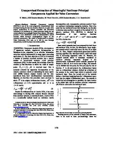
Fig. 2. False color composite for the pansharpened QB image of Tokyo, Japan.
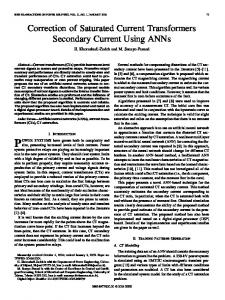
Fig. 1. Radiance reflection of white plate measured on Dec. 4, 2008, at (a) a sunlit place, (b) in a dark shadow of a building wall, (c) in a light shadow of a parapet beam and (d), (e) their ratios (shadow/sunlit).
indirectly from the open sky. The ratio of the radiances in the shadow and in the sunlit area was calculated. It is observed that the ratio increases as the sunlight gets weaker, and decreases as the wavelength gets longer. In Fig. 1, the range of wavelength for each spectral band of QB sensor is shown. There is a large difference between the dark and light shadows, which means the ratio is also affected by the darkness of shadow. A total of 26 spectral radiance measurements were carried out in Japan (23 times), Chile (2 times), and the USA (1 time) that covered a relatively wide range of site conditions and seasons. These results show the same tendency as the measurement on December 4, 2008 in which the spectral ratio of shadow is dependent on time and season, wavelength of sunlit, and the shadow casting condition (darkness). Although it is difficult to apply the results of the ground measurements to optical satellite images directly, these characteristics should be considered when shadow correction is carried out. III. STUDY AREA AND DATA A QB image of central Tokyo, Japan, was used as an example. The image was taken on March 20, 2007, at 10:48 AM. At the time of the image acquisition, the Sun elevation angle was 51.5 and the solar orientation was 155.3 clockwise from the north. The dynamic range of the image product is 11 bits, while the spatial resolution of the panchromatic (PAN) image is 0.62 m and that of the multi-spectral (MS) image is 2.49 m. The principal component (PC) spectral sharpening method was used to create a new 0.62-m-resolution image with 4 bands, shown in Fig. 2. This method replaces the PC band 1 of the MS image, which is based on principal component analysis,
Fig. 3. Flowchart of proposed shadow detection method.
with the high-resolution PAN band, and it scales the high-resolution band to match the PC band 1. Hence the image can be pansharpened without any distortion of the spectral information. The example image covers a ground area of about a 2.16 km . Since there are many mid-height and high-rise buildings in central Tokyo, significant parts of the original image are in the cast shadows of these buildings. Thus, the surface details in the shadow areas could not be directly observed in the original image. IV. OBJECT-BASED SHADOW EXTRACTION Several research efforts have extracted shadows from remote sensing images using pixel-based methods [3], [4]. Such methods, however, produce a number of extraction errors, such as white roofs in shadow areas, due to their high brightness values, and dark vehicles in sunlit areas, due to their low brightness values. To reduce these errors, we employed an object-based method, in which objects are recognized by size, shape, and other criteria. In this study, the semi-automated object-based method in Definiens Professional 5 software [11] was used to extract shadow areas. A flowchart of the proposed method is shown in Fig. 3. One PAN band and four MS band (R, G, B, and NIR) images that were obtained prior to the pansharpening process were employed. To reduce errors, a water mask obtained from GIS data was applied prior to shadow extraction. The proposed method includes three steps: segmentation, classification, and modification.
1298
IEEE JOURNAL OF SELECTED TOPICS IN APPLIED EARTH OBSERVATIONS AND REMOTE SENSING, VOL. 5, NO. 4, AUGUST 2012
A. Segmentation First, the pixels in the QB image were grouped into objects using a heuristic algorithm for image segmentation, in which objects are recognized in terms of four parameters: scale, color, smoothness, and compactness. The scale parameter determines the maximum allowable heterogeneity within an object. In general, the object size increases with an increase in the maximum allowable heterogeneity. Color is an important parameter for creating meaningful objects. The factors of smoothness and compactness are used in order to optimize image objects to create smooth or compact borders. Color, smoothness, and compactness are general variables that are used to optimize an object’s spectral homogeneity and spatial complexity [12]. The relationship between scale parameter, color, smoothness and compactness has been described in [13]. In this study, the scale parameter was determined as 20, which is relatively small, to create an object with one surface material. This parameter is an overall fusion value of the color heterogeneity and the shape heterogeneity. Although it does not have a unit, it is proportional to the area (pixels). Thus, it should be changed in proportion to the square of the resolution. The effects of color and shape were considered to be at the same level, such that the color factor was defined as 0.5. The compactness was also defined as 0.5, thus setting a weight that is equal to that of the smoothness. Since the brightness value of the PAN band was used to create objects in this step, the layer weight for the PAN band was set as 1.0 and for the MS bands as 0. Based on these assumptions, the entire image was segmented into 168,854 objects. B. Classification After the segmentation, the objects were classified into shadow and sunlit areas based on a threshold value , as determined from a histogram of the PAN band’s DN values. A threshold value of 167 was manually selected as the mean value of DN, based on the histogram in Fig. 4(a). From this histogram, the threshold value can be defined easily between two peaks. However, in some cases there are no easily distinguishable two peaks as in Fig. 4. Then the threshold value can be interactively defined by comparing the DN’s of several boundaries between shadow and sunlit areas. Chen et al. [15] also introduced a shadow index to extract shadow areas from multi-spectral images. Since the purpose of this study is to correct the shadow areas created by buildings, the objects that are smaller than 20 pixels, which is about the size of a vehicle, were removed from the extracted shadow areas. According to the results of the radiance measurements, the radiance ratio changes with the darkness level of the shadow. To enhance the accuracy of shadow correction, shadow objects were divided into three classes: dark-shadow, medium-shadow, and light-shadow, which correspond to shadow darkness between umbra and penumbra. Large shadow close to the foot of a large building was defined as dark-shadow while a lighter area at the border of shadow was defined as light-shadow. Since the darkness level of shadow cannot be measured for a satellite image, shadow objects were classified by their DNs. Fig. 4(b) shows a histogram of the shadow areas in the PAN band with the factor , which is used in the shadow correction process
Fig. 4. (a) Histogram of PAN band of QB image; (b) histogram of shadow areas of PAN band and factor describing darkness of shadow.
representing the relative weight of a dark-shadow or a lightshadow with respect to a medium-shadow. The lowest 5% and the highest 5% of DN were selected as the threshold values in order to distinguish dark- and light-shadows from mediumshadow, respectively, based on the histogram shown in Fig. 4(b). According to this process, in the QB image of Tokyo, the objects with a mean DN value of less than 100 were classified as dark-shadow, those between 100 and 150 as medium-shadow, and those higher than 150 but less than 167 as light-shadow. C. Modification In the modification step, the results after classification were improved by utilizing a neighbor relationship. The objects in sunlight having a border line over 90% with shadow objects were reclassified as being in shadow. Using this method, it is possible to reduce the errors that take place in the pixel-based extraction. Bright objects such as white roofs and light-colored vehicles in shadow can be reclassified as shadow areas. Following such modification, the objects in each class (dark-, medium-, light-shadow, and sunlit) were returned to the pixel level and were again segmented, using the information of the MS bands. This time, the layer weight of the PAN band was set as 0 and that of the MS band as 1.0. The scale parameters were also changed in different classes. Since the range of the DN values for sunlit areas is about twice of what it is for shadow areas, the scale parameter was set as 10 for dark- and medium-shadow areas, which was a half value for light-shadow and sunlit areas. The result of this shadow extraction is shown in Fig. 5, in which 22% of the entire image was extracted as shadow areas. By visually comparing this result with the original image, we see that most of the shadow areas were extracted correctly. However, there still remain several areas that could not be extracted properly, such as a bright roof in light-shadow. D. Comparison Between Object-Based and Pixel-Based Methods To compare the accuracy of detection obtained by objectbased and pixel-based methods, pixel-based shadow detection was also carried out using the same threshold values that were used in the object-based method. Areas with a DN of less than 167 in the PAN image were extracted as shadow areas. After the water mask was applied, 24% of the image was classified as shadow. Next, the results obtained using the object-based and pixel-based methods were compared with the original image.
LIU AND YAMAZAKI: OBJECT-BASED SHADOW EXTRACTION AND CORRECTION OF HIGH-RESOLUTION OPTICAL SATELLITE IMAGES
1299
Fig. 5. Result of shadow detection and classification with three darkness levels.
In the results of the pixel-based extraction, there was considerable noise such as small shadows cast by trees, which were not observed by the object-based method or in the original image. Also, materials with high reflectivity in shadow areas could not be extracted, such as white vehicles or bright roofs. Using the object-based method, however, it was possible to remove these errors. Since the object-based method extracts shadow areas on the basis of spectral heterogeneity, the small noise in the result can be reduced, and the bright objects in shadows can be identified by a neighbor relationship. V. SHADOW CORRECTION After the detection of shadow areas, shadow correction was performed. Three major algorithms—gamma correction, linear-correlation correction, and histogram matching—have been employed to correct detected shadow areas by Dare [3] and Sarabandi et al. [4]. Because, in these references, the linear-correlation correction method proved to be most effective for restoring a shadow’s brightness, we also employed this method in our shadow correction. There are two different approaches to the linear-correlation correction method. One is expressed by (1), which uses the mean value and standard deviation of all the shadow and sunlit areas to correct the spectral radiance of shadow areas [5], [14]. (1) where is the DN value in shadow, and is the DN value after correction; denotes the mean value and is the standard deviation. The second approach is based on a linear regression analysis using a dataset of the DN values of the shadow and sunlit areas [16]. Both these approaches, however, correct all the shadow areas using a single linear equation, even though this relationship changes depending on the darkness of the shadow. For this reason, some areas then display a big difference after correction, whether they are in shadow or in a sunlit zone. In this study, a piecewise linear equation [(2)] that considers the darkness level is proposed in order to correct shadow areas. (2)
Fig. 6. (a) Comparison of original and corrected DN values obtained using two methods for PAN band. (b) Comparison of original and corrected DN values obtained using the proposed method for MS bands.
(3) where is the ratio of the radiances in the shadow and sunlit areas for each spectral band; is the modification coefficient representing the darkness of the shadow, shown in (3); and is the factor obtained in the shadow detection step. From the QB image of Tokyo, was obtained as and as . Twelve pairs of samples with the same surface material (10 pairs in the medium-shadow class and two pairs in the light-shadow class) were manually selected from the shadow and sunlit areas to obtain the ratio . The DN values of the samples for each spectral band are shown in Fig. 6. Since the dark-shadow was always in the middle of a large shadow area, it was difficult to determine the surface material without having information from the ground. Thus, no sample was selected from the dark-shadow class. The ratio was calculated from the 10 pairs of samples in the mediumshadow class using a linear regression analysis. In the present case, , the reciprocal of inclination, was obtained as 0.15. Using , which is between 1 and 1, the dark-shadow areas can be corrected to be brighter, and the light-shadow areas can then connect to the shadow and sunlit areas in a natural transition. If we use the corrected DN values in a single linear equation, the same results are obtained for the medium-shadow class, but the results show even higher DN values than for sunlit objects in the light-shadow class [Fig. 6(a)]. On the other hand, the
1300
IEEE JOURNAL OF SELECTED TOPICS IN APPLIED EARTH OBSERVATIONS AND REMOTE SENSING, VOL. 5, NO. 4, AUGUST 2012
TABLE I CONFUSION MATRICES FOR VISUAL INSPECTION AND SUPERVISED CLASSIFICATION RESULTS OBTAINED FROM CORRECTED SHADOW-FREE IMAGE IN FIG. 8 FOR (a) SUNLIT AREAS AND (b) CORRECTED SHADOW AREAS
Fig. 7. Pansharpened and corrected shadow-free QB image in false color.
Fig. 8. Comparison between original and corrected QB images in (a) false color, (b) NDVI, and (c) supervised classification results.
results corrected by (3) go downward in the light-shadow class, as do the values of the samples selected in sunlit areas. The result of shadow correction after pansharpening is shown in Fig. 7. The histogram for the PAN band after shadow correction is shown in Fig. 4(a). As can be seen in the figure, the DN values in shadow areas (less than 167) move to larger values (that correspond to sunlit areas). It can be seen that using the proposed method, following shadow correction, the shadow and sunlit areas are connected with natural transitions. VI. VERIFICATION OF SHADOW CORRECTION To verify the efficiency of the shadow correction method, comparisons between the original and shadow-corrected QB images were carried out with respect to the NDVI value and supervised classification. A part of the image within the square in Fig. 7 is shown in Fig. 8. The effect of shadow is more dominant in the NIR band than in the other bands because the radiance ratio between shadow and sunlit areas decreases with an increase in the sunlight wavelength [Fig. 1(d), (e)]. In general, the NDVI value, which is obtained from NIR and red band images, tends to be lower in a shadow area than in a sunlit area. Fig. 8(b) shows a comparison of the NDVI images before and after shadow correction.
It is noted that some vegetation areas in shadow could not be detected due to their low NDVI values before the correction. However, the NDVI values of vegetation in shadow areas increased following shadow correction, which made it possible to detect vegetation in a cast shadow. The effects of shadow correction on supervised classification were also evaluated. Object-based supervised classification was carried out for both the original and corrected shadow-free images by the nearest neighbor method. Three objects were selected manually for each class as training data. The total area of all the training data shares about 5% of the image. A part of the results are shown in Fig. 8(c). The original QB image was labeled as eight classes: water, vegetation, railway tracks, roads, and roofs with three different colors, and shadow. The shadow-free image was classified into seven classes (without shadow) using the same training data. Because the spectral characteristics of the artifacts were similar, roads and roofs could not be distinguished very well, as shown in Fig. 8(c). We would note that the areas of the shadow class were re-classified into other land-cover classes. We performed visual inspection using a digital aerial photograph in order to verify the accuracy of the supervised classification result for the corrected shadow-free image in Fig. 8(a). Comparisons of the classified results for sunlit and corrected shadow areas are shown in Table I. For sunlit areas, the overall accuracy was 74.94 with a kappa coefficient of 0.61. For the corrected shadow areas, the overall accuracy was 71.87 with a kappa coefficient 0.57. Based on this comparison, the classification results show a similar level of accuracy for the sunlit and corrected-shadow areas, thus confirming that the proposed shadow correction method can effectively correct the radiance in shadow areas. A WV2 image of Tokyo taken on November 5, 2010 with a Pan band and 4 MS bands (B, G, R, and NIR) was also introduced to demonstrate the efficiency of the proposed shadow correction method for other optical sensors. Since the capability of the WV2 sensor is similar to QB’s, only the threshold value
LIU AND YAMAZAKI: OBJECT-BASED SHADOW EXTRACTION AND CORRECTION OF HIGH-RESOLUTION OPTICAL SATELLITE IMAGES
1301
VII. CONCLUSIONS
Fig. 9. Comparison between original and corrected WV2 images in (a) false color; (b) a part of NDVI and (c) supervised classification results. TABLE II CONFUSION MATRICES FOR VISUAL INSPECTION AND SUPERVISED CLASSIFICATION RESULTS OBTAINED FROM CORRECTED SHADOW-FREE IMAGE IN FIG. 9 FOR (a) SUNLIT AREAS AND (b) CORRECTED SHADOW AREAS
In this paper, a building shadow detection and correction method for high-resolution optical satellite images was proposed and examples were provided for a dense urban area. Twenty-six radiance measurements were performed to demonstrate the natural variability of the radiance ratio in different environments and shadow conditions. The characteristics of shadow obtained for the ground measurements gave us the motivation to develop a semi-automated shadow correction method. An object-based method was introduced to extract shadow areas from a QB image using brightness values and a neighbor relationship. The method showed higher shadow detection accuracy than the conventional pixel-based method, especially for bright materials in shadow. A piecewise linear-correlation equation was proposed to correct shadow pixels on the basis of DNs of sample areas in the QB image by employing three levels of shadow darkness. Verification of the shadow detection and correction method was carried out using a QB and a WV2 images of central Tokyo that were acquired in 2007 and 2010. The supervised classification results showed reasonable restoration of the brightness values in shadow areas. The pansharpened images were also generated to visually examine the correction effects. The NDVI images showed significant restoration of the NDVI value in shadow following correction, because this value is highly affected by shadow. Although further investigation is required, it was confirmed that land-cover classification of shadow areas can be significantly improved by applying the shadow detection and correction method proposed in this study. REFERENCES
for shadow and the ratio in each band should be defined manually. The comparison of the original and corrected WV2 images in false color is shown in Fig. 9(a). A part of NDVI and supervised classification results within the square in Fig. 9(a) are shown in Fig. 9(b), (c). We also conducted accuracy evaluation of the supervised classification results for the corrected shadow-free image by visual inspection, which are shown in Table II. For sunlit areas, the overall accuracy is 77.61 with a kappa coefficient of 0.66. For the corrected shadow areas, the overall accuracy is 77.27 with a kappa coefficient 0.63, very close to the sunlit areas. The application to the WV2 image shows the proposed method is also useful for other optical sensor images. However, the efficiency of shadow correction depends on the dynamic range of a sensor. As 8-bit images do not measure dark areas with the necessary high radiometric resolution, the quality of shadow extraction is severely reduced compared to 11-bit data.
[1] J. S. Shu and H. Freeman, “Cloud shadow removal from aerial photographs,” Pattern Recognit., vol. 23, no. 6, pp. 647–656, 1990. [2] V. K. Shettigara and G. M. Sumerling, “Height determination of extended objects using shadows in SPOT images,” Photogramm. Eng. Remote Sens., vol. 64, no. 1, pp. 35–44, 1998. [3] X. Huang and L. Zhang, “Morphological building/shadow index for building extraction from high-resolution imagery over urban areas,” IEEE J. Sel. Topics Appl. Earth Observ. Remote Sens. (JSTARS), vol. 5, no. 1, pp. 161–172, Feb. 2012. [4] P. M. Dare, “Shadow analysis in high-resolution satellite imagery of urban areas,” Photogramm. Eng. Remote Sens., vol. 71, no. 2, pp. 169–177, 2005. [5] P. Sarabandi, F. Yamazaki, M. Matsuoka, and A. Kiremidjian, “Shadow detection and radiometric restoration in satellite high resolution images,” in Proc. IEEE 2004 Int. Geoscience and Remote Sensing Symp. (IGARSS), 2004, vol. 6, pp. 3744–3747. [6] Y. Li, T. Sasagawa, and P. Gong, “Integrated shadow removal based on photogrammetry and image analysis,” Int. J. Remote Sens., vol. 26, no. 18, pp. 3911–3929, 2005. [7] J. Y. Rau, N. Y. Chen, and L. C. Chen, “True orthophoto generation of built-up areas using multi-view images,” Photogramm. Eng. Remote Sens., vol. 68, no. 6, pp. 581–588, 2002. [8] M. Song and D. L. Civco, “A knowledge-based approach for reducing cloud and shadow,” presented at the 2002 ASPRS-ACSM Annu. Conf. and FIG XXII Congr., Washington, DC, 2002. [9] K. Kouchi and F. Yamazaki, “Characteristics of tsunami-affected areas in moderate-resolution satellite images,” IEEE Trans. Geosci. Remote Sens., vol. 45, no. 6, pp. 1650–1657, 2007. [10] W. Zhou, G. Huang, A. Troy, and M. L. Cadenasso, “Object-based land cover classification of shaded areas in high spatial resolution imagery of urban area: A comparison study,” Remote Sens. Environ., vol. 113, no. 8, pp. 1769–1777, 2009. [11] Definiens [Online]. Available: www.ecognition.com
1302
IEEE JOURNAL OF SELECTED TOPICS IN APPLIED EARTH OBSERVATIONS AND REMOTE SENSING, VOL. 5, NO. 4, AUGUST 2012
[12] K. Navulur, Multispectral Image Analysis Using the Object-Oriented Paradigm. Boca Raton, FL: CRC Press, 2006, ch. 4, pp. 20–21. [13] M. Baatz and A. Schäpe, “Multiresolution Segmentation: An Optimization Approach for High Quality Multi-Scale Image Segmentation,” 2000 [Online]. Available: http://www.ecognition.cc/download/ baatz_schaepe.pdf [14] T. Nakajima, T. Guo, and Y. Yasuoka, “Simulated recovery of information in shadow areas on IKONOS image by combing ALS data,” presented at the 23rd Asian Conf. Remote Sensing (ACRS), Kathmandu, Nepal, 2002. [15] Y. Chen, D. Wen, L. Jing, and P. Shi, “Shadow information recovery in urban areas from very high resolution satellite imagery,” Int. J. Remote Sens., vol. 28, no. 15, pp. 3249–3254, 2007. [16] Q. Zhan, W. Shi, and Y. Xiao, “Quantitative analysis of shadow effects in high-resolution images of urban areas,” Int. Archives Photogrammetry, Remote Sensing and Spatial Information Sciences, vol. 36, pt. 8/W27, 2005. Wen Liu (S’10) was born in Hangzhou, China, in 1985. She received the B.S. and M.S. degrees in civil engineering from Chiba University, Chiba, Japan, in 2008 and 2010, respectively. She is currently pursuing the Ph.D. degree at the same university. Her research interest is in urban remote sensing using very-high-resolution optical sensors and synthetic aperture radar.
Fumio Yamazaki (M’03) was born in Ishikawa, Japan, on May 27, 1953. He received the M.S. degree in civil engineering from the University of Tokyo, Tokyo, Japan, in 1978. After serving as a Visiting Scholar at Columbia University, New York, NY, from 1984 to 1986, he received the Ph.D. degree in civil engineering from the University of Tokyo in 1987. He is currently a Professor of Urban Environment Systems in the Graduate School of Engineering at Chiba University, Chiba, Japan. He was also a Research Engineer at Shimizu Corporation, Japan, and worked as an Associate Professor at the University of Tokyo and a Professor at the Asian Institute of Technology, Thailand. His research interests include stochastic engineering mechanics, earthquake engineering, and more recently, the application of GIS and remote sensing technologies to disaster management. Prof. Yamazaki is a member of the Japan Society of Civil Engineers, the American Society of Civil Engineers, the Earthquake Engineering Research Institute, and the Seismological Society of America, among others.