Nov 27, 2017 - 4. Supported cables: 5. Details. 5. How to interface? 5. Example Codes. 7. Code 1: Arduino. 7. Elint Labz
Object Sensor Plug Product Manual
Updated on: 27th November 2017
Product Manual: Object Sensor Plug
INDEX
About Elint Labz
3
Introduction
4
Specification
4
Operating voltage: 5V
4
Variants
4
Supported cables:
5
Details
5
How to interface?
5
Example Codes
7
Code 1: Arduino
7
Elint Labz (www.elintlabz.in)
Page 1 of 6
Product Manual: Object Sensor Plug
About Elint Labz Elint Labz (usually abbreviated as EL) is an electronics design & development tools designer & manufacturer with headquarters in Bengaluru, India. We design, develop & manufacture development boards based on micro-controller & microprocessors, breakout boards for various sensors & actuators. Our domain & expertise is in the area of Electronics & Embedded Systems. Elint Labz was founded in 2014 however the actual operations started from 2015 when it became a full time subsidiary of Hogst Innovative Solutions Pvt. Ltd. & is presently a part of Ajaramara Group a conglomerate of various domains of industries, registered in India as Ajaramara Dynamics Pvt. Ltd. under Companies Act of 2013. As in the name company (Elint Labz) – Electronic intelligence (ELINT) is intelligence gathered by the use of electronic sensors, Laboratories (LABZ) are facilities that provides controlled conditions in which scientific or technological research, experiments and measurement may be performed. EL is an enterprise built to develop smart & intelligent electronics & EL is committed to help achieve electronics literacy in India. No matter the vision or skill level, our products and resources are designed to make electronics & programmable development hardware more accessible. Elint Labz as a platform helps developers & young engineers from prototyping to product development. We provide open source hardware solutions and small quantity manufacturing services using a design from manufacturing framework. We are a strong promoter of the maker movement in India, most of the manufacturing happens with support of our various Indian partners & couple of our collaboration partners who have manufacturing & sourcing facilities in Germany, Korea & Shenzhen. To know more visit the about us section on our website: http://elintlabz.in/about-us/ Elint Labz (HQ) 📮 #200 1st main Arekere MICO layout 2nd stage Bengaluru 560076 KA [Marked on Google Maps] ✆ +91 855 377 2525 📧
[email protected]
Elint Labz (www.elintlabz.in)
Page 2 of 6
Product Manual: Object Sensor Plug
Introduction
Object Sensor Plug is used to detect the obstacles present in front of the IR sensors. The main feature of this plug is that the sensitivity or detection range can be adjusted manually to meet the consumer’s requirement. This plug can be mounted anywhere using screws.
Specification
● Operating voltage: 5V ● Size: 30mm x 30mm ● Adjustable sensing range (1cm - 15cm)
Variants ● None
Elint Labz (www.elintlabz.in)
Page 3 of 6
Product Manual: Object Sensor Plug
Supported cables: 1. 3-3 A 2. 4-3 A 3. 4-4A
Details
Object Sensor Plug consists of an IR transmitter and IR receiver with amplifying circuit to detect the obstacles present in front of the IR sensors. The IR transmitter is basically an IR LED that emits infrared radiation. The IR receiver is basically a photodiode which can be used to receive the IR radiations. It also has a POT to adjust the sensing range, approximately 1cm to 15cm. There is an LED on the board which indicates the obstacles presence. Whenever the IR sensors detect the obstacle LED turns ON. There is a slide switch to select the modes of operation. ‘A’ represents the Auto mode and ‘M’ represents the Manual mode. In the Auto mode the IR transmitter is directly connected to the supply so that IR transmitter always emits the IR radiations. In the manual mode IR transmitter is connected to the T pin of the interfacing port so that the user can control the IR radiations.. Object Sensor plug is a digital input device to the interfacing system. It has an interfacing port with four pins named as G, V, R & T. Here G represents Ground, V represents VCC, R & T represents receiver and transmitter data pins. Note: The modulated IR signal reflects more on white surface and reflect less on black surface.
How to interface?
Use either of the supported interfacing cables to connect the Object Sensor Plug to the controller board. If the Object Sensor Plug is operated in the Auto mode then 3-3A or 4-3A cable is prefered. Since, in Auto mode T pin is directly pulled HIGH it is better not to connect plug’s T pin to the data pin on the controller board. Using 3-3A cable to connect the plug is simple as last pin at both the ports are left unconnected. If 4-3A cable is to be used then 3pin end of the cable is connected to the object sensor plug leaving T pin and 4 pin end of the cable must be connected to the controller board. If the Object Sensor Plug is operated in the Manual mode then 4-4A cable is prefered. In this mode the user provides the input signal to the T pin of the plug. While using 4-4A cable any end of the cable can be connected to the object sensor plug. Always ensure that black wire of the cable is connected to the G pin on both sides. Make sure that the data pins of the object sensor plug are connected to the digital pins on the controller board. The table given below shows the interfacing of object sensor plug with the controller board using both 4-3A cable and 4-4A cable. Elint Labz (www.elintlabz.in)
Page 4 of 6
Product Manual: Object Sensor Plug
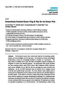
4-3A cable (Automatic mode)
4-4A cable (Manual mode)
In the below given picture we can see that 4-3A cable is used to connect object sensor plug which is configured in automatic mode to the pluguino board. The receiver data pin of the object sensor plug (R) is connected to the digital pin 7 on the controller board. In order to demonstrate the working of the Object Sensor Plug we have used the Buzzer plug to indicate whether the sensor has recognised an object or not. Buzzer turns ON if the obstacle is detected.
Elint Labz (www.elintlabz.in)
Page 5 of 6
Product Manual: Object Sensor Plug
Example Codes Code 1: Arduino #define Buzzer_pin 12 #define ObstaclePin 7 boolean isObstacle;
// buzzer plug is connected to 12th pin // object sensor plug is connected to 7th pin // variable to store the state of object sensor
void setup() { pinMode(ObstaclePin, INPUT); pinMode(Buzzer_pin, OUTPUT); }
// config 7th pin as an INPUT pin // config 12th pin as an OUTPUT pin
void loop() { isObstacle = digitalRead(ObstaclePin); // read the state of sensor and store if(isObstacle == LOW) // check whether obstacle is present { digitalWrite(Buzzer_pin, HIGH); // turn ON buzzer }
Elint Labz (www.elintlabz.in)
Page 6 of 6
Product Manual: Object Sensor Plug
else { digitalWrite(Buzzer_pin, LOW); }
// turn OFF buzzer
} Output video: https://youtu.be/gO7dH1RzxqQ
Elint Labz (www.elintlabz.in)
Page 7 of 6