846
J. Opt. Soc. Am. B / Vol. 23, No. 5 / May 2006
Lee et al.
Observation of cascade complete-chaos synchronization with zero time lag in laser diodes Min Won Lee, Jon Paul, Cristina Masoller, and K. Alan Shore School of Informatics, University of Wales, Bangor, Dean Street, Bangor LL57 1UT, Wales, United Kingdom, and Departament de Fisica i Enginyeria Nuclear, Universitat Politecnica de Catalunya, Colom 11, E-08222 Terrassa, Barcelona, Spain Received June 22, 2005; revised November 11, 2005; accepted November 28, 2005; posted December 8, 2005 (Doc. ID 62926) This paper reports the first experimental observation and theoretical description of zero time lag, completechaos synchronization using three laser diodes coupled in a unidirectional cascade configuration. The master laser is rendered chaotic by optical feedback from an external mirror. The output intensity of the master laser is injected into an intermediate laser, and the output intensity of this intermediate laser is in turn injected into a slave laser. The distances between the lasers are carefully adjusted such that the times of flight between the lasers are equal to the delay time in the external-cavity of the master laser. When the three lasers are subject to the same optical injection strength it is observed that their output intensities synchronize with zero time lag. The chaos synchronization has been confirmed by time traces and synchronization diagrams of the three laser outputs, and the null lag time has been measured from cross-correlation diagrams. Numerical simulations based on single-mode rate equations are in good qualitative agreement with the experimental observations. © 2006 Optical Society of America OCIS codes: 140.1540, 060.4510, 140.5960.
1. INTRODUCTION Chaos synchronization has received much attention since the pioneering work of Pecora and Carroll,1 with particular emphasis being given to the implementation of chaotic data encryption. A large number of encryption schemes using optical systems have been reported, with efficient message encoding and decoding having been achieved.2–10 There have been extensive studies of synchronization of coupled chaotic oscillators; see, e.g., Refs. 11 and 12. The present work acts to develop concepts from both of these fields. Because of their nonlinear response and ease of operation, the synchronization of semiconductor lasers subject to optical feedback has been given particular attention13, with novel forms of chaos synchronization in unidirectionally coupled semiconductor lasers having been investigated. These include anticipating synchronization14,15; dual synchronization16,17; synchronization in a phaselocking scheme,18 and two-mode synchronization.19 Chaos synchronization has also been achieved in mutually coupled semiconductor lasers.20–22 It was recently experimentally demonstrated that vertical-cavity surfaceemitting lasers can also be synchronized in both mutual23 and unidirectional coupling configurations.24 Semiconductor lasers subject to optical feedback can exhibit two different regimes of chaos synchronization, referred to as complete synchronization and generalized synchronization. These regimes can be distinguished by the lag time between the outputs of the synchronized lasers.25–27 In complete synchronization the lag time ⌬ between the lasers is equal to the difference between the time of flight c from the master laser to the slave laser and the round-trip time in the external cavity of the master laser 共⌬ = c − 兲.28 The achievement of complete 0740-3224/06/050846-6/$15.00
synchronization requires two similar lasers operating under similar conditions. The other regime of synchronization is termed generalized synchronization. Such synchronization is more robust to parameter mismatches between the lasers and can be achieved by injection locking using strong optical injection29 or via optical frequency detuning.30,31 In this regime the slave laser follows the dynamics of the master laser with a lag time equal to the time of flight 共⌬ = c兲. In this paper we demonstrate complete synchronization with zero time lag using three unidirectionally cascadecoupled distributed feedback (DFB) lasers for the first time. The lasers are termed master, intermediate, and slave lasers. The master laser is subject to optical feedback from an external-cavity mirror, whereas the intermediate and slave lasers are stand-alone lasers (openloop configuration).32,33 Complete synchronization has been widely studied in master–slave configurations, but no previous report has been made of complete synchronization using a cascadecoupled laser configuration. Generalized synchronization would be expected when a stand-alone intermediate laser and a stand-alone slave laser are coupled in a three-laser configuration. However, within the operating parameters that are required to effect generalized synchronization, there is a narrow window of operating parameters that can induce the intermediate and slave lasers to achieve complete synchronization, as has been demonstrated in the present work. The operating requirements to access this window are that the master feedback strength matches the injection strength of the master to the intermediate laser, and matches the injection strength of the intermediate laser to the slave. We have also demonstrated, for the first time to our © 2006 Optical Society of America
Lee et al.
knowledge, zero-time-lag synchronization between the three lasers. When the intermediate laser is synchronized with the master laser, the dynamics of the intermediate laser is the same as that of an external-cavity laser with delay time , and therefore, in general the slave laser synchronizes with a lag time of c2 − (c2 is the time of flight between the intermediate and slave lasers). In the present system, we consider a specific setup in which the flight time from the master to the intermediate laser, c1, and the flight time from the intermediate laser to the slave, c2, match the round-trip time of the master external cavity. For this case the time lag is zero. It is pointed out that in generalized synchronization, zero time lag between the lasers cannot be achieved. Therefore the presence of zero time lag gives further confirmation that complete synchronization has been achieved. As such, this is the first report of complete synchronization of three lasers and also the first demonstration of three lasers synchronized with zero time lag in a cascadecoupled configuration. The synchronization of three cascade-coupled lasers was demonstrated previously34 and was used to extract messages in wavelengthmultiplexed chaotic communications.35 However, in those demonstrations the observed lag time between any two lasers was equal to the corresponding time of flight, and therefore the observed behavior was generalized, not complete synchronization. This paper is organized as follows. Section 2 describes the experimental setup. Section 3 presents the experimental results on cascaded synchronization without time lag between three laser diodes. Section 4 presents the theoretical model used for the numerical simulations, which are presented in Section 5. Finally, Section 6 provides a summary of the results and the conclusion from the work.
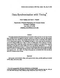
2. EXPERIMENTAL SETUP Figure 1 depicts schematically the experimental setup in which three DFB lasers are used as the master laser (ML), the intermediate laser (IL), and the slave laser (SL). The emission of each laser is collimated by an aspheric lens. The mirror M1 forms for the ML an external
Vol. 23, No. 5 / May 2006 / J. Opt. Soc. Am. B
847
cavity with 42 cm length that gives a round-trip time of = 2.8 ns. The neutral density filter NDF is used to vary the optical feedback ratio so that the ML is rendered chaotic. The ML is coupled to the IL through the beam splitters BS1 and BS3, and the IL is coupled to the SL through M2 and BS5. By these means, the lasers are coupled in a cascade configuration. The unidirectional coupling between the lasers is ensured by the optical isolators OI1 and OL2, which each provide −33 dB isolation. The halfwave plates HWP1 and HWP2 are used to adjust the polarization of coupling light with respect to the polarization of coupling laser emission. The coupling attenuators CA1 and CA2 are used to adjust the coupling ratios between the ML and IL and between the IL and SL, respectively. The isolator OI3 prevents back reflection from the photodetector PD3. The output of each laser is detected by 12 GHz bandwidth photodetectors PD1, PD2, and PD3 through BS2, BS4, and BS5, respectively. The photodetectors are all positioned at the same distance 共73 cm兲 from the corresponding laser to ensure a zero lag time. The outputs of the photodetectors are recorded with a 4 GHz bandwidth digital oscilloscope with 10 GS/ s sampling rate. To observe complete chaos synchronization between the three lasers, two conditions need to be satisfied. First, the optical frequencies of the lasers have to be identical. The lasers used for the experiment are driven by low noise current sources, and the bias currents are set as JM = 30.73 mA, JI = 31.6 mA, and JS = 34.7 mA (corresponding to 2.34Jth, 2.40Jth, and 2.68Jth respectively, where Jth is the threshold current of the free-running laser). The temperatures of the ML 共28.55° C兲, IL 共24.8 ° C兲, and SL 共24.23 ° C兲 are controlled with an accuracy of ±0.01 ° C. For these operating parameters, the lasers support single-mode emission at a wavelength of 1549.02 nm with 40 dB side-mode suppression. Secondly, the coupling ratios between the ML and the IL and between the IL and the SL have to be the same as the optical-feedback ratio of the ML. In the present experiment the optical-feedback ratio is adjusted to 2.4% of the ML output power, and suitably the optical injection ratios are adjusted to 2.4%. In order to observe zero-time-lag synchronization regime, a third condition must be met; the time of flight c1 from the ML to the IL and the time of flight c2 from the IL to the SL must be the same as the external cavity round-trip time . In the experimental setup the distances between the ML and the IL and between the IL and the SL are set as 84 cm, which is twice the external cavity length. This gives c1 = c2 = = 2.8 ns.
3. EXPERIMENTAL RESULTS
Fig. 1. Schematic diagram of the experimental setup. ML, master laser; IL, intermediate laser; SL, slave laser; , externalcavity round-trip time of the ML; c1, time of flight of ML–IL; c2, time of flight of IL–SL; BS, beam splitter; NDF, neutral density filter; M, mirror; OI, optical isolator; CA, coupling attenuator; HWP, half-wave plate; PD, photodetector.
Figure 2 displays the waveforms of the chaotic outputs of the three lasers in the complete synchronization regime. The waveforms have been recorded with 1000 data points with a 10 ns time interval. For clarity, the time traces of the IL and the SL are displaced; the upper trace is the output of the ML, the middle trace is the output of the IL, and the lower trace is the output of the SL. The waveforms are seen to be synchronized, and the time shift between them is zero.
848
J. Opt. Soc. Am. B / Vol. 23, No. 5 / May 2006
Fig. 2. Experimental time series of the synchronized chaotic laser outputs.
Lee et al.
The time lag ⌬ between two lasers is measured by the time shift ⌬t at which the cross-correlation coefficient is maximum. If the lasers are in complete synchronization, the maximum coefficient occurs at ⌬t = c − = 0. On the other hand, if the lasers are in generalized synchronization, the maximum coefficient occurs at ⌬t = c = 2.8 ns. The synchronization diagram of the ML versus the IL is displayed in Fig. 3(a), from which it can be seen that good quality synchronization is achieved. In Fig. 3(b) C共⌬t兲 is shown to peak at ⌬t = 0 [this peak is dominant compared to the subpeaks at ⌬t = ± 2.8 ns; the maximum crosscorrelation coefficient is C共0兲 = 0.83]. This proves that the ML and the IL are synchronized with zero time lag, i.e., with no lag time between them. The synchronization diagram of the ML versus the SL is displayed in Fig. 3(c). The degree of synchronization is reduced compared with Fig. 3(a), but it can clearly be seen that the lasers are synchronized. The crosscorrelation diagram [Fig. 3(d)] has a dominant peak at ⌬t = 0 [the maximum coefficient is C共0兲 = 0.65], which proves that the ML and the SL are also synchronized without a lag time. The synchronization diagram of the IL versus the SL is displayed in Fig. 3(e). From this figure it can be seen that good quality synchronization is also achieved. The crosscorrelation coefficient displayed in Fig. 3(f) also peaks at ⌬t = 0 [the maximum coefficient is C共0兲 = 0.71], which indicates again good synchronization without lag time.
4. MODEL In this section we present the theoretical model used to describe the above experimental findings. Each laser is modeled using single-mode rate equations. The equations for the ML include a delayed term for optical feedback, the equations for the IL include a term representing optical injection from the ML, and the equations for the SL include a term representing optical injection from the IL. The equations are Fig. 3. Experimental results. Synchronization diagram (a) of the ML versus the IL, (c) of the ML versus the SL, and (e) of the IL versus the SL; cross-correlation diagram (b) of the ML and the IL, (d) of the ML and the SL, and (f) of the IL and the SL.
The quality of chaos synchronization and the lag time between the waveforms of any two lasers can be quantified by the synchronization diagram and the maximum of the cross-correlation coefficient C共⌬t兲. Figure 3 displays results when zero-time-lag synchronization is achieved. The synchronization diagrams were obtained from the time traces recorded with 200 000 data points spanning a 4 s time interval. C共⌬t兲 was obtained by calculating the correlation coefficient between the outputs of two lasers when the output of one laser is continuously shifted an amount ⌬t with respect to the output of the other laser (time traces with 25 000 data points spanning a 400 ns time interval were used).31 The function C共⌬t兲 reveals the internal periodicity of the waveforms; the periodicity at the relaxation oscillation period corresponds to the time interval between two consecutive peaks of C共⌬t兲, and the periodicity at the external-cavity delay time corresponds to the time interval between two consecutive envelope peaks of C共⌬t兲.
˙ = k共1 + j␣兲共N − 1兲E + ␥ E 共t − 兲exp共− i 兲 E M M M T M 0 + 冑DM共t兲, ˙ = ␥ 共J − N − N 兩E 兩2兲, N M n M M M
共1兲 共2兲
˙ = k共1 + j␣兲共N − 1兲E + ␥ E 共t − 兲exp共− i 兲 E I I I I M c1 0 c1 + 冑DI共t兲, ˙ = ␥ 共J − N − N 兩E 兩2兲, N I n I I I
共3兲 共4兲
˙ = k共1 + j␣兲共N − 1兲E , E S S S + ␥REI共t − c2兲exp共− i0c2兲 + 冑DS共t兲
共5兲
˙ = ␥ 共J − N − N 兩E 兩2兲. N S n S S S
共6兲
Here EM, EI, and ES (NM, NI, and NS) are the slowly varying complex amplitudes (carrier densities) of the master, intermediate, and slave lasers, respectively. The lasers
Lee et al.
Vol. 23, No. 5 / May 2006 / J. Opt. Soc. Am. B
are assumed to have identical free-running optical frequency 共0兲 and parameters; k is the cavity loss, ␣ is the linewidth enhancement factor, D is the spontaneous emission noise intensity, is a Gaussian white noise, ␥n is the inverse carrier lifetime and J is the normalized injection current 共Jth = 1兲. ␥M is the feedback strength, and␥I and ␥S are the injection strengths. It can be observed from Eqs. (1)–(6) that when ␥M = ␥I = ␥S and D = 0 the lasers can be synchronized with the slowly varying complex amplitudes related as EI共t − 兲exp共− i0兲 = EM共t − c1兲exp共− i0c1兲,
共7兲
ES共t − 兲exp共− i0兲 = EI共t − c2兲exp共− i0c2兲
共8兲
and the output intensities related by IS共t兲 = II共t − c2 + 兲 = IM共t + 2 − c1 − c2兲.
849
weakly developed chaos, and in the parameter region, where it exhibits so-called low-frequency fluctuations (which case is not presented here). For comparison, the optical injection strengths of the IL and the SL are much larger than the feedback strength of the ML (␥I = ␥S = 8␥M = 400 ns−1; other parameters as in Fig. 4). In Fig. 6 generalized synchronization is achieved with time lags. In obtaining Figs. 6(a), 6(c), and 6(e), the time lags between the lasers have been taken into account. In Figs. 6(b), 6(d), and 6(f), the dominant peak in the cross-correlation diagrams occurs at ⌬t = 3 ns 关C共3兲 = 0.96兴 for the ML–IL; ⌬t = 6 ns 关C共6兲 = 0.86兴 for the ML– SL; ⌬t = 3 ns 关C共3兲 = 0.95兴 for the IL–SL. Figure 7 displays the numerically simulated intensity time traces in generalized synchronization regime. As in
共9兲
In particular, when c1 = c2 = the intensities are synchronized without a lag time. In generalized synchronization the output intensities of the lasers are related by the usual lag times, which are the flight times between them: IM共t兲 = a1II共t + c1兲,
II共t兲 = a2IS共t + c2兲,
共10兲
Since the lasers are identical, a1 = a2 = a; an approximated analytical expression for the coefficient a was given in Eq. (10) of Ref. 36. In Section 5 we show that, in spite of the important simplifications of the model (which neglects the detailed feedback geometry of the DFB grating and the nonlinear gain saturation due to spatial and spectral hole burning), the simulations from this model are in good qualitative agreement with the experimental observations.
5. NUMERICAL RESULTS The equations are simulated with the parameters k = 600 ns−1, ␥n = 1 ns−1, ␣ = 3, c1 = c2 = = 3 ns, 0 = 0 rad, J = 2.4, and D = 10−5 ns−1. With 5 ps time integration step, time traces are obtained as output intensities of the lasers 共IM,I,S = = 兩EM,I,S兩2兲. A digital low-pass filter is applied to the intensity time series to simulate the 4 GHz bandwidth recording. The correlation functions are calculated using time series spanning 1 s. Figure 4 displays results when the master laser exhibits weakly developed chaos 共␥M = 50 ns−1兲, and the injection parameters satisfy the complete synchronization condition 共␥M = ␥I = ␥S兲. The synchronization diagrams and cross-correlation plots show features remarkably similar to the experimental observations. In the three crosscorrelation plots the peak at ⌬t = 0 is dominant with respect to the peaks at ⌬t = ± 3 ns. The maximum crosscorrelation coefficient is, for the ML–IL C共0兲 = 0.94; for the ML–SL C共0兲 = 0.8, and for the IL–SL C共0兲 = 0.78. Figure 5 displays the chaotic waveforms of the ML (upper trace), the IL (middle trace), and the SL (lower trace). Zero time lag synchronized chaotic oscillations are clearly observed. The numerical simulations indicate that the complete synchronization solution of the three lasers is stable both in the parameter region, where the master laser exhibits
Fig. 4. Numerical results for parameters such that ␥M = ␥I = ␥S = 50 ns−1. (a) Synchronization diagram of the master laser versus the intermediate laser, (b) the corresponding cross-correlation diagram as a function of time shift ⌬t, (c) the synchronization diagram of the master laser versus the slave laser, (d) the corresponding cross-correlation diagram, (e) the synchronization diagram of the intermediate laser versus the slave laser, and (f) the corresponding cross-correlation diagram.
Fig. 5. Numerically simulated output intensities in complete synchronization (parameters as in Fig. 4).
850
J. Opt. Soc. Am. B / Vol. 23, No. 5 / May 2006
Lee et al.
our knowledge, complete chaos synchronization of the three lasers without a time lag. For such synchronization, three conditions have to be satisfied. (1) The lasers need to operate at the same wavelength. (2) The optical feedback rate of the master laser should be equal to the optical injection rates of the intermediate and slave lasers. (3) The flight times of master–intermediate laser and the intermediate-slave laser need to match the delay time of the master external cavity. The cross-correlation diagrams have shown that the three lasers are in complete synchronization with the maximum cross-correlation coefficient for zero time lag. Based on a simple model for three coupled single-mode lasers, the experimental findings have been qualitatively well reproduced theoretically. The proposed scheme can also be employed to synchronize with zero time lag any number of slave systems to a master system that has a time delay, as long as the time of flight between each system is equal to the master delay time.
ACKNOWLEDGMENTS Fig. 6. Results of numerical simulations with parameters corresponding to generalized synchronization (␥T = 50 ns−1, ␥I = ␥R = 400 ns−1). Synchronization diagram (a) of the ML versus the IL, (c) of the ML versus the SL, and (e) of the IL versus the SL; crosscorrelation diagram (b) of the ML and the IL, (d) of the ML and the SL, and (f) of the IL and the SL.
The work is supported by the European Union OCCULT (Optical Chaos Communication Using Laser Transmitters) project (IST-2000-29683) and EPSRC (Engineering and Physical Sciences Research Council) project (GR/ S78650/01). C. Masoller acknowledges support from the “Ramon and Cajal” Program (Spain). M. W. Lee is the corresponding author and can be reached via e-mail at
[email protected].
REFERENCES 1. 2.
3.
Fig. 7. Numerically simulated output intensities in the generalized synchronization regime (parameters as in Fig. 6). The arrows indicate the lag times between the synchronized intensities.
Fig. 2, the time traces of the IL and the SL are displaced for clarity (the arrows indicate the synchronization lag points). It is observed that the chaotic oscillations are synchronized with lag times corresponding to the flight times c1 = c2 = 3 ns.
4.
5.
6.
7.
6. CONCLUSIONS We have studied experimentally and theoretically zerotime-lag synchronization of three DFB lasers in a unidirectional cascade configuration. We have considered a setup consisting of a master laser that is subject to optical feedback, an intermediate laser that is subject only to optical injection from the master, and a slave laser that is subject only to optical injection from the intermediate laser. From this we have demonstrated, for the first time to
8.
9. 10.
L. M. Pecora and T. L. Carroll, “Synchronization in chaotic systems,” Phys. Rev. Lett. 64, 821–824 (1990). I. Fischer, Y. Liu, and P. Davis, “Synchronization of chaotic semiconductor laser dynamics on sub-ns timescales and its potential for chaos communication,” Phys. Rev. A 62, 801-14 (2000). A. Uchida, S. Yoshimori, M. Shinozuka, T. Ogawa, and F. Kannari, “Chaotic on—off keying for secure communications,” Opt. Lett. 26, 866–868 (2001). S. Tang and J.-M. Liu, “Message encoding–decoding at 2.5 Gbits/ s through synchronization of chaotic pulsing semiconductor lasers,” Opt. Lett. 26, 1843–1845 (2001). J.-B. Cuenot, L. Larger, J.-P. Goedgebuer, and W. T. Rhodes, “Chaos shift keying with an optoelectronic encryption system using chaos in wavelength,” IEEE J. Quantum Electron. 37, 849–855 (2001). C. R. Mirasso, J. Mulet, and C. Masoller, “Chaos shiftkeying encryption in chaotic external-cavity semiconductor lasers using a single-receiver scheme,” IEEE Photonics Technol. Lett. 14, 456–458 (2002). T. Heil, J. Mulet, I. Fischer, C. R. Mirasso, M. Peil, P. Colet, and W. Elsäßer, “ON/OFF phase shift keying for chaosencrypted communication using external-cavity semiconductor lasers,” IEEE J. Quantum Electron. 38, 1162–1170 (2002). J. Paul, S. Sivaprakasam, P. S. Spencer, and K. A. Shore, “Optically modulated chaotic communication scheme with external-cavity length as a key to security,” J. Opt. Soc. Am. B 20, 497–503 (2003). M. W. Lee, L. Larger, and J.-P. Goedgebuer, “Transmission system using chaotic delays between lightwaves,” IEEE J. Quantum Electron. 39, 931–935 (2003). J. Paul, M. W. Lee, and K. A. Shore, “3.5-GHz signal transmission in an all-optical chaotic communication
Lee et al.
11. 12. 13. 14. 15. 16. 17. 18. 19.
20. 21.
22.
23.
24.
scheme using 1550-nm diode lasers,” IEEE Photonics Technol. Lett. 17, 920–922 (2005). M. G. Rosenblum, A. S. Pikovsky, and J. Kurths, “From phase to lag synchronization in coupled chaotic oscillators,” Phys. Rev. Lett. 78, 4193–4196 (1997). D. J. DeShazer, R. Breban, E. Ott, and R. Roy, “Detecting phase synchronization in a chaotic laser array,” Phys. Rev. Lett. 87, 044–101 (2001). S. Sivaprakasam and K. A. Shore, “Demonstration of optical synchronization of chaotic external-cavity laser diodes,” Opt. Lett. 24, 466–468 (1999). C. Masoller, “Anticipation in the synchronization of chaotic semiconductor lasers with optical feedback,” Phys. Rev. Lett. 86, 2782–2785 (2001). S. Tang and J.-M. Liu, “Experimental verification of anticipated and retarded synchronization in chaotic semiconductor lasers,” Phys. Rev. Lett. 90, 101–1–4 (2003). Y. Liu and P. Davis, “Dual synchronization of chaos,” Phys. Rev. E 61, R2176–R2179 (2000). A. Uchida, S. Kinugawa, T. Matsuura, and S. Yoshimori, “Dual synchronization of chaos in one-way coupled microchip lasers,” Phys. Rev. E 67, 220–1–8 (2003). A. Murakami, “Phase locking and chaos synchronization in injection-locked semiconductor lasers,” IEEE J. Quantum Electron. 39, 438–447 (2003). M. W. Lee and K. A. Shore, “Two-mode chaos synchronization using a multi-mode external-cavity laser diode and two single-mode laser diodes,” J. Lightwave Technol. 23, 1068–1073 (2005). J. Mulet, C. Masoller, and C. R. Mirasso, “Modeling bidirectionally coupled single-mode semiconductor lasers,” Phys. Rev. A 65, 815–1–12 (2002). J. M. Buldú, R. Vicente, T. Pérez, C. R. Mirasso, M. C. Torrent, and J. García-Ojalvo, “Periodic entrainment of power dropouts in mutually coupled semiconductor lasers,” Appl. Phys. Lett. 81, 5105–5107 (2002). T. Heil, I. Fischer, W. Elsäßer, J. Mulet, and C. R. Mirasso, “Chaos synchronization and spontaneous symmetrybreaking in symmetrically delay-coupled semiconductor lasers,” Phys. Rev. Lett. 86, 795–798 (2001). N. Fujiwara, Y. Takiguchi, and J. Ohtsubo, “Observation of the synchronization of chaos in mutually injected verticalcavity surface-emitting semiconductor lasers,” Opt. Lett. 28, 1677–1679 (2003). Y. Hong, M. W. Lee, P. S. Spencer, and K. A. Shore, “Synchronization of chaos in unidirectionally coupled
Vol. 23, No. 5 / May 2006 / J. Opt. Soc. Am. B
25. 26.
27.
28.
29.
30. 31. 32.
33.
34. 35.
36.
851
vertical-cavity surface-emitting semiconductor lasers,” Opt. Lett. 29, 1215–1217 (2004). I. V. Koryukin and P. Mandel, “Two regimes of synchronization in unidirectionally coupled semiconductor lasers,” Phys. Rev. E 65, 201–1–5 (2002). A. Locquet, C. Masoller, and C. R. Mirasso, “Synchronization regimes of optical-feedback-induced chaos in unidirectionally coupled semiconductor lasers,” Phys. Rev. E 65,205–1–12 (2002). A. Uchida, N. Shibasaki, S. Nogawa, and S. Yoshimori, “Transient characteristics of chaos synchronization in a semiconductor laser subject to optical feedback,” Phys. Rev. E 69, 201–1–9 (2004). Y. Liu, Y. Takiguchi, P. Davis, T. Aida, S. Saito, and J.-M. Liu, “Experimental observation of complete chaos synchronization in semiconductor lasers,” Appl. Phys. Lett. 80, 4306–4308 (2002). Y. Liu, P. Davis, Y. Takiguchi, T. Aida, S. Saito, and J.-M. Liu, “Injection locking and synchronization of periodic and chaotic signals in semiconductor lasers,” IEEE J. Quantum Electron. 39, 269–278 (2003). A. Murakami and J. Ohtsubo, “Synchronization of feedback-induced chaos in semiconductor lasers by optical injection,” Phys. Rev. A 65,826–1–7 (2002). M. W. Lee, J. Paul, I. Pierce, and K. A. Shore, “Frequencydetuned synchronization switching in chaotic DFB laser diodes,” IEEE J. Quantum Electron. 41, 302–307 (2005). R. Vicente, T. Pérez, and C. R. Mirasso, “Open-versus closed-loop performance of synchronized chaotic externalcavity semiconductor lasers,” IEEE J. Quantum Electron. 38, 1197–1204 (2002). M. W. Lee, J. Paul, S. Sivaprakasam, and K. A. Shore, “Comparison of closed-loop and open-loop feedback schemes of message decoding using chaotic laser diodes,” Opt. Lett. 28, 2168–2170 (2003). S. Sivaprakasam and K. A. Shore, “Cascaded synchronization of external-cavity laser diodes,” Opt. Lett. 26, 253–255 (2001). J. Paul, S. Sivaprakasam, and K. A. Shore, “Dual-channel chaotic optical communications using external-cavity semiconductor lasers,” J. Opt. Soc. Am. B 21, 514–521 (2004). J. Revuelta, C. R. Mirasso, P. Colet, and L. Pesquera, “Criteria for synchronization of coupled chaotic externalcavity semiconductor lasers,” IEEE Photonics Technol. Lett. 14, 140–142 (2002).