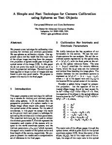
Figure 2. Diffuse rendering of the integrated LIDAR 3-D triangle mesh for the fountain-P11 data-set. LIDAR techniques, i.e. benchmark results can be classified.
On Benchmarking Camera Calibration and Multi-View Stereo for High Resolution Imagery C. Strecha CVLab EPFL Lausanne (CH)
W. von Hansen FGAN-FOM Ettlingen (D)
L. Van Gool CVLab ETHZ Z¨urich (CH)
P. Fua CVLab EPFL Lausanne (CH)
U. Thoennessen FGAN-FOM Ettlingen (D)
Abstract In this paper we want to start the discussion on whether image based 3-D modelling techniques can possibly be used to replace LIDAR systems for outdoor 3D data acquisition. Two main issues have to be addressed in this context: (i) camera calibration (internal and external) and (ii) dense multi-view stereo. To investigate both, we have acquired test data from outdoor scenes both with LIDAR and cameras. Using the LIDAR data as reference we estimated the ground-truth for several scenes. Evaluation sets are prepared to evaluate different aspects of 3D model building. These are: (i) pose estimation and multi-view stereo with known internal camera parameters; (ii) camera calibration and multi-view stereo with the raw images as the only input and (iii) multi-view stereo.
1. Introduction Several techniques to measure the shape of objects in 3-D are available. The most common systems are based on active stereo, passive stereo, time of flight laser measurements (LIDAR) or NMR imaging. For measurements in laboratories, active stereo systems can determine 3-D coordinates accurately and in real-time. However, active stereo is only available for controlled indoor environments. A second technique which is also applicable to measure outdoor environments is LIDAR. In contrast to image based techniques, LIDAR systems are able to directly produce a 3-D point cloud based on distance measurements with an accuracy of less than 1 cm. The downside are high costs for the system and a time consuming data acquisition. Automatic reconstruction from multiple view imagery already is a low-cost alternative to laser systems, but could even become a replacement once the geometrical accuracy of the results can be proven. The aim of this paper is to investigate whether image based 3-D modelling techniques could possibly replace LIDAR systems. For this purpose we have acquired LIDAR data and images from outdoor scenes.
Figure 1. Diffuse rendering of the integrated mesh for the Herz-Jesu-P8 data-set.
LIDAR
3-D triangle
The LIDAR data will serve as geometrical ground truth to evaluate the quality of the image based results. Our evaluation sets include camera calibration as well as the evaluation of dense multi-view stereo. Benchmark data-set for both, camera calibration (internal and external) [9] and for stereo and multi-view stereo [16, 15] are available. To generate ground truth usually a measurement techniques has to be used which is superior to the evaluation techniques. Seitz et al. [16] and Scharstein et al. [15] use a laser scanner and an active stereo system, respectively, to get the advantage w.r.t. multi-view stereo. In the ISPRS calibration benchmark [9] the ground truth is estimated on large resolution images, i.e. for a more accurate feature localisation, and only small resolution images are provided as benchmark data. However, in these data-sets ground truth is measured and is assumed to be known exactly. Our approach is different from that. Similar to Seitz et al. [16] we use laser scans to obtain ground truth but we also estimate the variance of these measurements. Image based acquisition techniques are evaluated relative to this variance. This allows to compare different algorithms w.r.t. to each other. Moreover we can specify, based on this variance, at which point image based techniques become similar to
Figure 2. Diffuse rendering of the integrated mesh for the fountain-P11 data-set.
LIDAR
3-D triangle
LIDAR techniques, i.e. benchmark results can be classified into correct if its relative error approaches the uncertainty range of the ground truth. Our benchmark data contains realistic scenes that could also be of practical interest, i.e. outdoor scenes for which active stereo is not applicable. This is a major difference to existing data-sets. We use furthermore high resolution images to be competitive with LIDAR. The paper is organised as follows: Sec. 2 deals with the LIDAR system used for our experiments. The preparation of the raw point cloud and the integration into a combined triangle mesh is discussed. Sec. 2.2 describes the generation of ground truth for the images from the LIDAR data. This includes the camera calibration and the generation of a per pixel depth and variance for each image. Sec. 3 evaluates different aspects of image based 3-D acquisition. In particular these are camera calibration and multi-view stereo reconstruction.
2. Ground truth estimation from LIDAR data 2.1. LIDAR acquisition The datasource for ground truth in our project is laser scanning (LIDAR). A laser beam is scanned across the object surface, measuring the distance to the object for each position. We had a Zoller+Fr¨ohlich IMAGER 5003 laser scanner at our disposition. Multiple scan positions are required for complex object surfaces to handle missing parts due to occlusions. Even though fully automatic methods exist for registration, we have chosen a semi-automatic way utilising software provided by the manufacturer in order to get a clean reference. 2-D targets are put into the scene and marked interactively in the datasets. Then the centre coordinates are automatically computed and a registration module computes a least squares estimation of the parameters for a rigid trans-
form between the datasets. Poorly defined targets can be detected and manually removed. The resulting standard deviation for a single target is 1.1 mm for the Herz-Jesu and 1.5 mm for the Ettlingen-castle data-set. The targets are visible in the camera images as well and are used to link LIDAR and camera coordinate systems. First, some filters from the software are applied to mask out bad points resulting from measurements into the sky, mixed pixels and other error sources. Then, the LIDAR data is transformed into a set of oriented 3-D points. Furthermore, we integrated all data-set into a single highresolution triangle mesh by using a Poisson based reconstruction scheme. See Kazhdan [7] for more details. A rendering of the resulting mesh is shown in figs. 1 and 2. We are now provided with a huge triangle mesh in a local coordinate system defined by one of the LIDAR scan positions. The next section deals with the calibration of the digital cameras in this coordinate system.
2.2. Image acquisition Together with the LIDAR data the scenes have been captured with a Canon D60 digital camera with a resolution of 3072 × 2028 square pixels. In this section we describe the camera calibration and the ground truth 3-D model preparation by using the LIDAR data. Our focus is thereby not only on the ground truth estimation itself but also on the accuracy of our ground truth data. The LIDAR 3-D estimates are themselves the result of a measurement process and therefore given by 3-D points and their covariance matrix. Our aim is to propagate the variance into our image based ground truth estimation. This is an important point for the preparation of ground truth data in general. Errors for the multi-view stereo evaluation are introduced by: (i) the 3-D accuracy of the LIDAR data itself and (ii) by the calibration errors of the input cameras. The latter does influence the quality of multi-view stereo reconstructions strongly. Evaluation taking these calibration errors into account should therefore be based on per image reference depth maps (more details are given in sec. 3.2) as opposed to Seitz et al. [16], who evaluate the stereo reconstructions by the Euclidean 3-D distance between estimated and ground truth triangle mesh.
2.3. Ground truth camera calibration LIDAR data and camera images are linked via targets that are visible in both datasets. Thus the laser scanner provides 3-D reference coordinates that can be used to compute the calibration parameters for each camera. For the camera calibration we assume a perspective camera model with radial distortion [6]. The images are taken without changing the focal length, such that the internal camera parameters θint = {f, s, x0 , a, y0 , k1 , k2 } (K-matrix and radial distortion parameters k1,2 ) are assumed to be constant for all
points Yj and the 2-D image measurements yij . The expected value of all internal and external camera parameters θ = {θint , θext1 , . . . , θextN } can be written as: � E[θ] = p(y� )p(θ � | y� ) θ � dy� dθ � . (1) Here p(y� ) is the likelihood of data, i.e. among all 3-D � only those will have points Yi� and image measurements yij a large likelihood that are close to the estimated values y: � � � � T −1 � ) ∝ exp −0.5(yij − yij ) Σij (yij − yij ) p(yij � � � p(Yj� ) ∝ exp −0.5(Yj − Yj� )T Σ−1 Y (Yj − Yj ) (2) Figure 3. Example of target measurements for the Herz-Jesu data.
The second term, p(θ � | y� ), is the likelihood of the calibration. This is a Gaussian distribution and reflects the accuracy of the calibration, given the data points y� . This accuracy is given by the reprojection error: e(θ) =
N � M � i
j
T
(Pi (θ)Yj − yij ) Σ−1 ij (Pi (θ)Yj − yij ) ,
� where Pi (θ) projects a 3-D point Yj to the image point yij and the calibration likelihood becomes:
p(θ | y) ∝ exp (−0.5e(θ)) .
(3)
The covariance Σ of the camera parameters is similarly given by: � T Σ = p(y� )p(θ � | y� ) (E[θ � ]−θ � ) (E[θ � ]−θ � ) dy� dθ � .
Figure 4. Example of feature tracks and their covariance. A small patch around the feature position is shown for all images. Underneath the covariance is shown as a gray-level image.
(4) To compute the solution of eqs. (1) and (4), we apply a sampling strategy. The measurement distribution p(y) is sampled and given a specific sample y� the parameters θ � are computed as the ML estimate of eq. (3): θ � = arg max{log p(θ | y� )} . θ
images. The external camera parameters are the position and orientation of the camera described by 6 parameters θext = {α, β, γ, tx , ty , tz }. The total number of parameters θ for N images is thus 7+6N . To calibrate the cameras we used M targets, which have been placed in the scene (shown in fig. 3). The 3-D position Yj ; j = 1. . .M and the covariance ΣY for these are provided by the laser scan software. In addition we used matched feature points across all images. From the around 20000 feature tracks we kept 200 as tie points. These have been selected as to have long track size and large spatial spreading in the images. We checked these remaining tracks visually for their correctness. In each input image i we estimated the 2-D positions yij and the covariance matrices Σij of the targets and the feature points. Examples are given in fig. 4. Let y denote all measurements, i.e. the collection of 3-D
(5)
Using eq. (5) and eq. (2) we can approximate the expected values and the covariance in eqn. (1) and (4) by a weighted sum over the sample estimates. As a result we obtain all camera parameters θ by E[θ] and their covariance Σ. This is a standard procedure to estimate parameter distributions, i.e. their mean and covariance.
2.4. Ground truth 3-D model Given the mean and variance of the camera calibration we are now in the position to estimate the expected value of the per pixel depth and variance. Again we sample the camera parameter distribution given by E[θ] and Σ in eq. (1) and eq. (4): � � T exp − 12 (E[θ] − θ � ) Σ−1 (E[θ] − θ � ) , (6) p(θ � ) = 7+6N 1 2π 2 | Σ | 2
by camera calibration techniques [6]. The third step takes the input images, which have often been corrected for radial distortion, and the camera parameters and establishes dense correspondences or the complete 3-D model (see [16] for an overview). We divided our data in to three categories which are used to evaluate several aspects of the 3-D acquisition pipeline:
Figure 5. Four images (out of 25) of the fountain-R25 data-set.
and collect sufficient statistics for the per pixel depth values. This goes in two stages. First, we find the first intersection of the laser scan triangle mesh with the sampled camera rays. Secondly, we sample the error distribution of the laser scan data around this first triangle intersection. The result is the mean Dlij and variance Dσij of the depth value for all pixels i. Note, that this procedure allows to evaluate multi-view stereo reconstructions independent on the accuracy of the camera calibration. If the performance of the stereo algorithm is evaluated in 3-D (e.g. by the Euclidean distance to the ground truth triangle mesh [16]) the accuracy of the camera calibration and the accuracy of the stereo algorithm is mixed. Here, the evaluation is relative to calibration accuracy, i.e. pixels with a large depth variance, given the uncertainty of the calibration, will influence the evaluation criterion accordingly. Large depth variance pixels appear near depth boundaries and for surface parts with a large slant. Obviously, these depth values vary most with a varying camera position. The reference depth maps and their variance will only be used for evaluation of multiview stereo in sec. 3.2. When the goal is to evaluate a triangle mesh without a camera calibration, the evaluation will be done in 3-D equivalent to [16]. This applies to the first two categories of data-sets described in sec. 3.
3. Evaluation of image based 3-D techniques The 3-D modelling from high resolution images as the only input has made a huge step forward in being accurate and applicable to real scenes. Various authors propose a so called structure and motion pipeline [2, 12, 13, 14, 17, 21, 22]. This pipeline consists of mainly three steps. In the first step, the raw images undergo a sparse-feature based matching procedure. Matching is often based on invariant feature detectors [11] and descriptors [10] which are applied to pairs of input images. Secondly, the position and orientation as well as the internal camera parameters are obtained
• 3-D acquisition from uncalibrated raw images: The data-sets in this category are useful to evaluate techniques that take their images from the internet, e.g. flickr (see for instance Goesele et al. [5]), or for which the internal calibration of the cameras is not available. It is useful to evaluate here the camera parameter estimation as well as the accuracy of the 3-D triangle mesh that has been computed from those cameras. Unfortunately, algorithms that produce a triangle mesh from uncalibrated images are still rare. Fully automatic software is to our knowledge not available such that we restrict the evaluation to the camera calibration, as will follow in the next section. • 3-D acquisition with known internal cameras: Often, it is possible to calibrate the internal camera parameters by using a calibration grid. These data-set are the ideal candidate to study the possibility to replace LIDAR scanning by image based acquisition. Results that integrate the camera pose estimation and the 3-D mesh generation could not be obtained. • Multi-View Stereo given all camera parameters: These data-set are prepared to evaluate classical MultiView Stereo algorithms similar to the Multi-View Stereo evaluation by Seitz et al. [16]. The data-set [1] are named by the convention: sceneName-XN, where X=R,K,P correspond to the three cathegories above ((R)aw images given, (K) matrix given, (P)rojection matrix given); N is the number of images in the data-set. In practice image based reconstructions should consist of and combine calibration and multi-view stereo. This is reflected by the first two categories. However, often one can find that both problems are handled separately. We therefore included one category for multi-view stereo.
3.1. Camera calibration To compare results of self-calibration techniques based on our ground truth data we first have to align our ground truth camera track with the evaluation track by a rigid 3-D transformation (scale, rotation and translation). This procedure transforms the coordinate system of the evaluation into our coordinate system. We used a non-linear optimisation of the 7 parameters an minimise:
Figure 6. Camera calibration for the fountain-R25 data-set in fig. 5. ARC 3D [3] (left) and Martinec et al. [8] (right). 0.1
0.05 0 -0.05 -0.1
0.05 0 -0.05 -0.1
0
5
10
15
20
25
5
10
15
20
0.1 y-distance [m]
0.05 0 -0.05 -0.1 10 15 camera index
-0.05
0
5
20
25
10
15
20
25
20
25
camera index 0.1
Martinec
0.05 0 -0.05 -0.1
5
0
camera index
Martinec
0
0.05
25
z-distance [m]
0.1
ARC-3D Martinec
-0.1 0
camera index
x-distance [m]
0.1
ARC-3D Martinec
z-distance [m]
ARC-3D Martinec
y-distance [m]
x-distance [m]
0.1
Martinec
0.05 0 -0.05 -0.1
0
5
10 15 camera index
20
25
0
5
10 15 camera index
Figure 7. Position error [m] of the camera calibration (Martinec et al. [8] - blue, ARC-3D [3]-red) for the fountain-R25 data (top) and the Herz-Jesu-R23 data (bottom). The green error bars indicate the 3σ value of the ground truth camera positions.
� = (E[θ] − θeval )T Σ−1 (E[θ] − θeval ), where θ and Σ includes now the subset of all camera position and orientation parameters. For the evaluation we used ARC-3D [3] and obtained results by Martinec et al. [8]. ARC-3D is a fully automatic web application. Martinec et al. [8] scored second in the ICCV 2005 challenge “Where am I”. Both methods suc-
cessfully calibrated all cameras for the fountain-R25 dataset. For the Herz-Jesu-R23 data only Martinec et al. [8] was able to reconstruct all cameras. ARC-3D succeeded to calibrate four of the 21 cameras. The result of this automatic camera calibration is shown in fig. 6. In this figure we show the position and orientation of the cameras (both ground truth and estimated cameras). Fig. 7 shows the dif-
Figure 8. Multi-view stereo results for FUK (left), ST4 (middle) and ST6 (right) on the Herz-Jesu-P8 data-set. The top images show the variance weighted depth difference (red pixels encode an error of larger that 30σ; green pixels encode missing LIDAR data; the relative error between 0. . .30σ is encoded in gray 255. . .0). Diffuse renderings of the corresponding triangle meshes are shown at the bottom.
ference in (x,y,z) position for each of the cameras w.r.t. the ground truth position. The errors bars indicate the 3σ value of our ground truth camera positions. Note, the decreasing variance for a higher camera indices, which can in this case be explained by a decreasing distance to the fountain [1]. The variance weighted average distance is 1.62σ (3.5σ) for ARC-3D (Martinec) for this scene. The variance weighted average distance for the Herz-Jesu-R23 data-set is 15.6σ (Martinec).
3.2. Multi-view stereo Dense multi-view stereo applied to outdoor scenes cannot rely on visual hulls that are very useful for indoor stereo applications [16]. Our test images have high resolution in order to meet the LIDAR precision and do not capture the object from all around. During data acquisition we also encountered problems due to pedestrians and changing light conditions. These aspects form a particular challenge for outdoor stereo reconstructions. As input to the multi-view stereo algorithms we provide the ground truth camera calibration as estimated in sec. 2.2, the images, which have been corrected for radial distortion, the bounding volume of the scene as well as the minimal/maximal depth value w.r.t. each input image. Results for this input have been obtained by Furukawa et al. [4] and Strecha et al. [19, 20] (providing two implementations). In the remainder we will abbreviate this three results by FUK, ST4 and ST6 for [4, 19, 20], respectively. Furukawa et al. [4] scores best in completeness and accuracy in the multi-view stereo evaluation [16]. They
get accurate results also when using only a small amount of images. Strecha et al. [19, 21] proposed a PDE-based formulations which is applicable to high resolution images. The same author provides the results of [20] on a downscaled version of the data-sets. All results are given by a single triangle mesh similar to [16]. The results of the multiview stereo approaches are shown in figs. 8 and 9 for the fountain-P11 and the Herz-Jesu-P8 data-sets. Their numeric values can be found in table 1. The accuracy of the stereo reconstruction Dsij is evaluated by building a histogram hk over the relative errors: � � � ij (7) hk ∝ δk | Dl − Dsij |, Dσij . ij
Dlij is the expected value of the LIDAR depth estimate at pixel position i and camera j and Dσij its corresponding variance. Furthermore, δk () is an indicator function which evaluates to 1 if the depth difference | Dlij − Dsij | falls within the variance range [kDσij , (k + 1)Dσij ] and evaluates to 0 otherwise. The stereo estimate Dsij is obtained from a 3-D triangle mesh by computing the depth of the first triangle intersection with the j th camera ray going through pixel i. All depth estimates for which the absolute difference with the ground truth is larger than 30Dσij and all pixels for which the multiview stereo reconstruction does not give depth estimates are collected all together in the last (k = 11) bin. These are all pixels indicated by red in figs. 9 and 8. The relative error histogram for the fountain-P11 and Herz-Jesu-P8 data
Figure 9. Multi-view stereo results for FUK (left), ST4 (middle) and ST6 (right) on the fountain-P11 data-set similar to fig. 8.
70 60 50
FUK ST4 ST6
60 occupancy %
occupancy %
70
FUK ST4 ST6
40 30 20 10
50 40 30 20 10
0
2
4
6
8
10
12
0
2
3σ
4
6
8
10
12
3σ
Figure 10. Histograms of the relative error occurrence for the reference view in fig. 8 of the Herz-Jesu-P8 data (left) and the reference view in fig. 9 of the fountain-P11 scene (right). The last (11th ) bin collects the occurrence of an relative error larger than 30σ.
are shown in fig. 10. They can be interpreted as follows: ∼ 58% (∼ 43%) of the stereo depths for Furukawa et al. [4] lie within the 3σ range of the LIDAR data for the fountainP11 (Herz-Jesu-P8) data-set; for ∼ 10% (∼ 27%) either no stereo depth exists or the error is larger than 30 times the LIDAR variance. The three evaluated algorithms are very different. Furukawa et al. [4] is based on feature matching between pairs of images. 3-D points and their normals are computed and the final mesh is obtained by a Poisson reconstruction. [20] is a MRF formulation that evaluates a certain number of discretised depth states. Similar formulations are widely used in small resolution stereo [15] where the number of states is
Herz-Jesu-P8 rel. error compleat. FUK ST4 ST6
2.98 3.16 5.03
89.53% 76.59% 70.05%
fountain-P11 rel. error compleat. 2.04 2.28 4.09
73.02% 87.06% 85.57%
Table 1. Numeric values for the mean relative error and the compleatness.
limited. The PDE-based multi-view stereo approach [19] evolves a depth map starting from an initial depth estimate [18]. The results show that Furukawa et al. [4] has the
best overall performance. However, all multi-view stereo results are still far away from the accuracy of the LIDAR.
4. Summary and conclusions In this paper we investigated the possibility to evaluate 3-D modelling of outdoor scenes based on high resolution digital images using ground truth acquired by a LIDAR system. We prepared evaluation sets for camera calibration and multi-view stereo and evaluated the performance of algorithms which have been shown to perform well on current benchmark data-sets and that scale to high resolution input. The ground truth data was prepared such that the evaluation can be done relative to the accuracy of the LIDAR data. This is an important point which enables a fair comparison between benchmark results as well as to the LIDAR measurements. The variance weighted evaluation is necessary to determine when a data-set can be treated a being solved. The best results for camera calibration deviate in the order of σ from the ground truth positions and by ≈ 3σ for dense depth estimation. We hope that the data-sets, of which we have shown only a part in this paper, can help to close the gap between LIDAR and passive stereo techniques. This should already be possible when passive stereo techniques can find and handle pixel accurate correspondences also for high resolution input images. The data-set are available at [1].
Acknowledgements Many thanks to Yasu Furukawa and Daniel Matrinec for running their algorithms on our data-sets, Maarten Vergauwen to provide the login to ARC-3D and Jochen Meidow for useful discussions. This research was supported in part by by EU project VISIONTRAIN and KULeuven GOA project MARVEL.
References [1] Multi-view evaluation - http://cvlab.epfl.ch/data, 2008. [2] A. Akbarzadeh, J. Frahm, P. Mordohai, B. Clipp, C. Engels, D. Gallup, P. Merrell, M. Phelps, S. Sinha, B. Talton, L. Wang, Q. Yang, H. Stewenius, R. Yang, G. Welch, H. Towles, D. Nist´er, and M. Pollefeys. Towards urban 3D reconstruction from video. In Int. Symp. of 3D Data Processing Visualization and Transmission , pages 1–8, 2006. [3] ARC 3D. http://www.arc3d.be, 2007. [4] Y. Furukawa and J. Ponce. Accurate, dense, and robust multiview stereopsis. In Proc. Int’l Conf. on Computer Vision and Pattern Recognition , pages 1–8, 2007. [5] N. Goesele, M. Snavely, B. Curless, H. Hoppe, and S. Seitz. Multi-view stereo for community photo collections. In Proc. Int’l Conf. on Computer Vision , 2007. [6] R. Hartley and A. Zisserman. Multiple View Geometry in Computer Vision. Cambridge University Press, ISBN: 0521623049, 2000.
[7] M. Kazhdan, M. Bolitho, and H. Hoppe. Poisson surface reconstruction. In Symposium on Geometry Processing, pages 61–70, 2006. [8] D. Martinec and T. Pajdla. Robust rotation and translation estimation in multiview reconstruction. In Proc. Int’l Conf. on Computer Vision and Pattern Recognition , 2007. [9] ISPRS working group III/1 2004-2008. http://www.commission3.isprs.org/wg1/, 2007. [10] K. Mikolajczyk and C. Schmid. A performance evaluation of local descriptors. IEEE Transactions on Pattern Analysis and Machine Intelligence , 27(10):1615–1630, 2005. [11] K. Mikolajczyk, Tuytelaars.T., C. Schmid, A. Zisserman, J. Matas, F. Schaffalitzky, T. Kadir, and L. Van Gool. A comparison of affine region detectors. Int’l Journal of Computer Vision , 65(1-2):43–72, 2005. [12] D. Nist´er. Automatic passive recovery of 3D from images and video. In Int. Symp. of 3D Data Processing Visualization and Transmission , pages 438–445, Washington, DC, USA, 2004. IEEE Computer Society. [13] M. Pollefeys, L. Van Gool, M. Vergauwen, F. Verbiest, K. Cornelis, J. Tops, and R. Koch. Visual modeling with a hand-held camera. Int’l Journal of Computer Vision , 59(3):207–232, 2004. [14] T. Rodriguez, P. Sturm, P. Gargallo, N. Guilbert, A. Heyden, J. Menendez, and J. Ronda. Photorealistic 3D reconstruction from handheld cameras. Machine Vision and Applications, 16(4):246–257, sep 2005. [15] D. Scharstein and R. Szeliski. A taxonomy and evaluation of dense two-frame stereo correspondence algorithms. Int’l Journal of Computer Vision , 47(1/2/3):7–42, 2002. [16] S. Seitz, B. Curless, J. Diebel, D. Scharstein, and R. Szeliski. A comparison and evaluation of multi-view stereo reconstruction algorithms. In Proc. Int’l Conf. on Computer Vision and Pattern Recognition , pages 519–528, Washington, DC, USA, 2006. IEEE Computer Society. [17] N. Snavely, S. Seitz, and R. Szeliski. Photo tourism: exploring photo collections in 3D. In SIGGRAPH ’06, pages 835–846, New York, NY, USA, 2006. ACM Press. [18] C. Strecha. Multi-view stereo as an inverse inverence problem. PhD thesis, PSI-Visics, KU-Leuven, 2007. [19] C. Strecha, R. Fransens, and L. Van Gool. Wide-baseline stereo from multiple views: a probabilistic account. Proc. Int’l Conf. on Computer Vision and Pattern Recognition , 1:552–559, 2004. [20] C. Strecha, R. Fransens, and L. Van Gool. Combined depth and outlier estimation in multi-view stereo. Proc. Int’l Conf. on Computer Vision and Pattern Recognition , pages 2394– 2401, 2006. [21] C. Strecha, T. Tuytelaars, and L. Van Gool. Dense matching of multiple wide-baseline views. In Proc. Int’l Conf. on Computer Vision , pages 1194–1201, 2003. [22] A. Zaharescu, E. Boyer, and R. Horaud. Transformesh: a topology-adaptive mesh-based approach to surface evolution. In Proc. Asian Conf. on Computer Vision , volume 2 of LNCS 4844, pages 166–175. Springer, November 2007.