representation leads to simple modular arithmetic with arbitrary moduli, while using standard arithmetic components such as carry-save and carry-propagate.
On Building General Modular Adders from Standard Binary Arithmetic Components Ghassem Jaberipur1,2, Behrooz Parhami3, and Saeed Nejati1 1
Dept. of Electrical & Computer Engineering, Shahid Beheshti Univ., Tehran, Iran School of Computer Sci., Inst. for Research in Fundamental Sci. (IPM), Tehran, Iran 3 Dept. of Electrical & Computer Engineering, Univ. of California, Santa Barbara, USA 2
Abstract—We introduce an excess-δ representation of residues for residue number system (RNS) arithmetic, in which a flag bit selects one or the other subrange within the full range of n-bit values. We show that our special representation leads to simple modular arithmetic with arbitrary moduli, while using standard arithmetic components such as carry-save and carry-propagate adders that have been extensively optimized for area, power, and a host of other composite figures of merit. Further advantages of a unified treatment, as opposed to a multiplicity of specialized schemes previously proposed in connection with particular classes of moduli such as 1 and 2 2 1, include simplified design process, 2 verification, testing, and fault tolerance. Both gate-level analyses and VLSI synthesis results point to advantages in latency, area, and/or power compared with other proposed designs in the literature.
carry-save and carry-propagate adders (CSA, CPA) that have been extensively optimized for area, power, and a host of other composite figures of merit. Further advantages of a unified treatment, as opposed to a multiplicity of specialized schemes, include the applicability of a single strategy for fault tolerance. Both gate-level analyses and VLSI synthesis point to advantages in latency, area, and/or power compared with other proposed implementations in the literature. The rest of this paper is organized as follows. After discussing mod-(2 δ) adders in Section 2, we define our excess-δ representation in Section 3, and then use it for implementing modular adders in Section 4. Cost-performance comparisons are offered in Section 5, followed by conclusions in Section 6.
2. Modulo-( 1. Introduction A Residue number system (RNS) consists of k pairwise relatively prime moduli. A number X is represented in as 〈| | , … , | | 〉, where | | ∈ 0, 1 denotes X mod m. The cardinality or dynamic range of equals the product ∏ of the moduli [1]. Implementation of add, subtract, or multiply in such an RNS is distributed on k computing channels corresponding to the k moduli, thus replacing a relatively slow operation on a wide operand by k independent and concurrent operations of the same kind with smaller operands. Therefore, balanced-latency channels are naturally desirable. Improved RNS addition [2-4], multiplication [5-8], and conversion [9-12] algorithms, sometimes based on new encodings [13], appear regularly in the literature. Moduli of the form 2 δ are popular due to ease of designing fast adders, especially for δ 1 [14] and δ 3 [16], where addition circuits with only one n-bit adder in the critical path are possible. However, substantial effort may be needed for designing multiple arithmetic units for other δ (e.g., 5, 7, for n = 4) from scratch, including the laborintensive and error-prone optimization process for high speed and power economy in each case [2]. We introduce an excess-δ representation for mod2 δ residues that leads to unified modular adders for all δ ∈ 3, 5, 7, … , 2 1 , where our designs use standard arithmetic components, such as
Modular Adders from Standard Arithmetic Components G. Jaberipur, B. Parhami, and S. Nejati
) Adders
General mod-m addition of n-bit mod-m residues and (0 , , and 2 2 ) can be described as in Eqn. 1, where δ 2 [16]. | |
|
δ 2 δ| , if , otherwise
(1)
Hiasat [16] cites three prior works [17-19], that also implement Eqn. 1, but less efficiently. Hiasat’s scheme forms two different sets of propagate and generate signals in positions where the binary representation of δ has a 1. One of these sets is later selected via the carry-out of δ, which is computed by carry-lookahead (CLA) logic dedicated exclusively to compute the required carry-out, thus saving some area and delay. A recent realization of Eqn. 1 [2] is similar to that of [16], but postpones the selection operation until the actual sum results are available, thus providing advantages in area and time. The aforementioned designs all entail the undesirable fan-out of n owing to the fact that one selection signal controls n multiplexors. Eqn. 1 can be transformed into Eqn. 2, where … δ, and is the logical complement of (i.e., 1 – ).
[Page 1 of 5]
|
|
2 2 , if δ, otherwise
| |
δ
(2)
45th Asilomar Conf. Signals, Systems, and Computers Pacific Grove, CA, November 6-9, 2011
Direct implementation of Eqn. 3 requires a CSA, followed by a CPA and a conditional subtraction. In what follows, we propose a new method and representation that obviate the need for the final subtraction. In the mod-(2 1) adders of [15] and [14], corresponding to 1, δ 2 1 and , δ 1, respectively, two O(log n) additions (similar to those in Eqn. 1) have been fused in one end-around carry-lookahead addition. However, this two-in-one technique works only for CLA and cannot be applied to other addition schemes (e.g., those with lower area/energy requirements, such as ripple-carry addition). Neither can it be generalized to other values of δ in (1, 2 – – 1). To remedy the latter problem, we endeavor to postpone the conditional subtraction of δ in Eqn. 2, fusing it with the next modular operation (or with the final conversion to binary). This would intuitively require flagging the interim sum | | with φ , as a reminder of the required compensating subtraction operation, hence our representation.
3. Excess- Representation A natural encoding of mod-(2 δ) residues uses n-bit words representing integers in 0, 2 δ 1. Realization of Eqn. 2, based on this natural encoding entails a δ-weighted inverted end-around carry subtraction, requiring a second n-bit CPA. To avoid this overhead, we propose a special representation. Definition 1 (Excess-δ representation): A mod(2 δ) residue is encoded as a (flag, magnitude) pair (φ , μ ), such that φ ∈ 0,1 , μ ∈ 0, 2 1, and μ φ δ. □ Eqn. 3 represents a modified version of Eqn. 2, based on the new representation, where φ , μ , φ , μ , φ , μ , and the interim sum is computed based on Eqn. 4. |
|
,| |
φ ,μ δ
μ
μ
1
φ
(3) φ δ
(4)
Table I illustrates some examples of how Eqns. 3 and 4 work for m = 29; that is, n = 5 and δ 3. Table I Mod-29 addition examples (n = 5, = 3). 28 0 3 3 28 1
0 0 1 0 1 0
28 29 6 3 31 1
1 0 28 25 28 2
1 0 1 1 1 0
4 0 31 28 31 2
32 32 34 31 59 6
0 0 0 1 0 1
Modular Adders from Standard Arithmetic Components G. Jaberipur, B. Parhami, and S. Nejati
0 0 2 31 27 6
4. A Reconfigurable Modular Adder φ δ represent the third term Let 1 φ of in Eqn. 4, which has a value in δ, 0, δ . We can reasonably restrict δ as 0 δ 2 and thus represent it as an ( 1)-bit unsigned number, δ . Consequently, can be encoded – . . . as the 1’s-complement number … . Eqn. set 5, which describes the bits of in terms of those of δ, and the input flags φ and φ , can be easily derived from the truth relations of Table II. φ ∧φ , φ ∧φ ∧
(5) ∨φ ∧φ ∧
0
1
Eqn. 6 shows how is computed in terms of the bits of μ , of μ , and of the sign-extended . 2
∑
1
2
(6)
We convert the Σ term of Eqn. 6 to its carry-save form by means of an n-bit CSA. The result is described by Eqn. 7, where and represent the sum and carry signals of a full adder that computes , for 0 1, and . The Σ term of Eqn. 7 can be computed by any n-bit adder, in a generic manner, including fast CLAs. Eqn. 8 describes the resultant interim sum, where is the carry-out of the generic adder. ∑
2
2
(7)
∑
2
2
(8)
To compute , we note that because 0 δ 2 2 δ, the parenthesized expression in Eqn. 8 should have a value in {0, 1}. Therefore, . Eqn. 9 is the logical equation for based on the latter arithmetic equation and can be derived via a simple truth table. φ
∧
∨
∨
∧
(9)
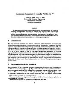
δ) Fig. 1 depicts the proposed unified mod-(2 adder architecture that implements the computations described in Eqns. 5-9. Note that in parallel prefix realization of the n-bit adder, the two most significant carry signals become available at the same time. Therefore, the most significant sum bit and the sum flag are also available at the same time.
0 0 2 28 27 3
Table II Truth table for bits of F. 0 0 1 1
[Page 2 of 5]
0 1 0 1
δ 0 0 δ
0 0 0 1
0 0
… … … … …
0 0
0 0
45th Asilomar Conf. Signals, Systems, and Computers Pacific Grove, CA, November 6-9, 2011
Table III Area/delay evaluation of Fig. 1. Component F box CSA
Fig. 1 Unified mod-(2n – ) adder. Our scheme has six advantages compared with previously published methods: (1) The use of only standard off-the-shelf components (e.g., full and half adders, parallel prefix nodes), facilitates upgrading of the design when new and superior versions become available; (2) The generic nature of the main n-bit adder expands the design space, allowing the best adder architecture to be chosen; (3) Latency is reduced by virtue of using only one n-bit CPA on the critical path; (4) Unified design for all values of δ leads to identical circuitry for all RNS channels, reducing the design, verification, and testing efforts, and enhancing regularity; (5) Reconfiguration is facilitated by placing the δ value in a writable register, allowing low-cost fault tolerance, as in [13]; (6) The dynamic range can be adjusted with high resolution via selection of suitable set of δ values. For example, given n = 5, starting with the moduli set {32, 31} adding one modulus at a time until {32, 31, 29, 27, 25, 23, 19, 17}, dynamic ranges on the order of 210, 215,220,225, 229, 233, and 233 are obtained.
5. Synthesis and Comparisons To compare the area and delay of the proposed adder with the latest relevant work [2], and with the designs in [17] and [16], we begin with the same gate-level evaluation of area and delay used in the references: we count each basic gate as having unit area and delay, with XOR gates counting double. The results are reported in Table III, assuming that, as in the best design of [2], the main n-bit adder is of the Kogge-Stone [20] parallel prefix (KSPP) variety. Each full adder in the CSA is assumed to imply 7 units of area and 4 units of delay [21], with the first XOR delay overlapping with the box computation.
Modular Adders from Standard Arithmetic Components G. Jaberipur, B. Parhami, and S. Nejati
Delay 2 2
KSPP
2 log
3
Fig. 2
2 log
7
Ref. [2]
2 log
7
Area 3 2 7n 3 1 log 1.5 3 3 1 log 11.5 1 6 9 log 1 13 8
Table IV provides some detail on how the area and delay of the n-bit KSPP adder is evaluated, where pgh stands for the propagate ( ∨ ), generate ( ∧ ), and half-sum ( ∧ ) signals. There are n of the 3-gate pgh boxes, n XORs for the final sum bits, at most 0.5n bottom parallel-prefix nodes and log leftmost nodes, each with 2 gates, and 1 log 1.5n + 1 other nodes, each with 3 gates. Therefore, the unit-gate area of the KSPP adder adds up to 3 1 log + 1.5n + 3. The gate-level evaluation of Table III indicates the same delay for our adder and the one in [2]. The area difference between the latter and our proposed design is expressed by Eqn. 10. The first term is negative for 2 1 (e.g., 3, 5, 9, 17).
3
log 3 log
3
1 1
log 1.5
9 log
(10)
It is not difficult to verify that 0 for 3, 5. However, the case n = 3 lacks practical significance. Also, synthesis results (Table V) show that the difference for the more practical data paths with 5 is only 0.7% in added area for the proposed design, while the power dissipation is 2.4% less. For a more reliable evaluation, we described the designs in [17], [16], and [2], along with our proposed adder, in VHDL code, validated them for , δ ∈ 5, 15 , 5, 3 , 8, 125 , 8, 65 , and used the codes as inputs to a 0.13μm CMOS technology synthesis process via the Synopsys design compiler. Table V and Figs. 2-5 show the synthesis results. Table IV Area/delay evaluation of a KSPP adder.
[Page 3 of 5]
Component pgh boxes PP node
Delay 1 2 log 2
XORs Total
2 log
3
Area 3n 3 1 log 3.5 3 2 3 1 log 1.5 3
45th Asilomar Conf. Signals, Systems, and Computers Pacific Grove, CA, November 6-9, 2011
Table V Synthesis results. m n
δ
17 5 15
29 5
3
131 8 125
191 8 65
Design [Ref.]
Delay Area Power (ns) (µm2) (µW)
[17]
1.082
1032
1098
[16]
1.163
718
743
[2]
0.821
922
1036
Proposed
0.798
917
999
[17]
1.077
1050
1133
[16]
1.098
704
773
[2]
0.795
899
1021
Proposed
0.799
906
997
[17]
1.176
1988
2151
[16]
1.464
1757
1973
[2]
0.954
2173
2133
Proposed
0.864
1716
1893
[17]
1.182
1994
2103
[16]
1.291
1336
1234
[2]
0.846
1700
1987
Proposed
0.877
1721
1938
Fig. 2 Synthesis-based area comparisons.
Fig. 3 Synthesis-based delay comparisons.
Four design points are assessed in Table V. In the first design point (m = 17, n = 5, = 15), all four bits in the binary representation of δ are 1s. In the second and fourth design points, δ has two 1s in its 4-bit and 7-bit encodings (δ 2 1 and 2 1), respectively. Finally, in the third instance, six of the seven bits in the binary representation of δ are 1s. For the first and third design points, our proposed approach fares better in all three measures (delay, area, and power) compared with the design of [2]. In particular, our design shows nearly 20% advantage in terms of the power-delay product figure of merit (1635 versus 2035). Figs. 2-4 show the synthesis-based comparisons in graphical form. In particular, Fig. 3 contrasts the balanced delay of our proposed design and that of [17] for the various δ weights to the imbalance in the other designs. Fig. 5 depicts the performance of the various designs, using the composite power-delay product (PDP) figure of merit. We see that, though not universally superior to other designs, our proposed scheme fares well in most cases and may even be the preferred method in other cases when design uniformity, ease of verification/testing, and fault tolerance are taken into account.
Modular Adders from Standard Arithmetic Components G. Jaberipur, B. Parhami, and S. Nejati
[Page 4 of 5]
Fig. 4 Synthesis-based power comparisons.
Fig. 5 Synthesis-based comparisons of PDP.
45th Asilomar Conf. Signals, Systems, and Computers Pacific Grove, CA, November 6-9, 2011
6. Conclusion We have proposed a unified method for designing modular adders that leads to highly competitive designs, even when compared against schemes that are restricted to special moduli. Our method also offers other advantages in design regularity, use of standard arithmetic building blocks, and ease and efficiency of incorporating fault tolerance schemes. The regularity introduced should ease VLSI layout and also render FPGA-based implementations more attractive. The standard building blocks used include carry-save and carry-propagate adders that have been extensively optimized for area, power, and a host of other composite figures of merit over the years, and continue to undergo additional improvements, as new designs appear in the literature (see, e.g., [22]). Our scheme was made possible by a special representation of arbitrary residues, in which a flag bit indicates a possible postponed subtraction. We presented quantitative comparisons of our designs with those previously published in the literature, using both detailed gate-level analyses and VLSI synthesis. The results pointed to advantages in latency, area, and/or power consumption, compared with other implementations appearing in literature. We are now examining various possibilities for improving our designs, with particular attention to forward and reverse conversion processes.
Acknowledgment G. Jaberipur’s research at IPM has been supported in part under grant CS1389-2-03.
References [1] A. Omondi and B. Premkumar, Residue Number Systems: Theory and Implementation, Imperial College Press, 2007. [2] R. A. Patel, M. Benaissa, N. Powell and Said Boussakta, “Novel Power-Delay-Area-Efficient Approach to Generic Modular Addition,” IEEE Trans. Circuits and Systems I, Vol. 54, No. 6, pp. 1279–1292, 2007. [3] H. T. Vergos and C. Efstathiou, “Efficient Modulo 2n + 1 Adder Architectures,” Integration, the VLSI J., Vol. 42, No. 2, pp. 149–157, 2009. [4] Tso-Bing Juang, Chin-Chieh Chiu, Ming-Yu Tsai, “Improved Area-Efficient Weighted Modulo 2 1 Adder Design With Simple Correction Schemes,” IEEE Trans. Circuits and Systems II, Vol. 57, No. 3, pp. 198–202, 2010. [5] J. C. Bajard, M. Kaihara, and T. Plantard, “Selected RNS Bases for Modular Multiplication,” Proc. 19th IEEE Symp. Computer Arithmetic, pp. 25–32, 2009. [6] H. T. Vergos and C. Efstathiou, “Design of Efficient Modulo 2n + 1 Multipliers,” IET Computers & Digital Techniques, Vol. 1, No. 1, pp. 49-57, 2007.
Modular Adders from Standard Arithmetic Components G. Jaberipur, B. Parhami, and S. Nejati
[7] J. W. Chen and R. H. Yao, “Efficient Modulo 2n + 1 Multipliers for Diminished-1 Representation,” IET Circuits, Devices & Systems, Vol. 4, No. 4, pp. 291300, 2010. [8] R. Chaves and L. Sousa, “Improving Residue Number System Multiplication with More Balanced Moduli Sets and Enhanced Modular Arithmetic Structures,” IET Computers & Digital Techniques, Vol. 1, No. 5, pp. 472–480, 2007. [9] M. Bhardwaj, T. Srikanthan, and C. T. Clarke, “A Reverse Converter for the 4-Moduli Super Set {2n − 1, 2n, 2n + 1, 2n+1 + 1},” Proc. 14th IEEE Symp. Computer Arithmetic, pp. 168–175, 1999. [10] B. Cao, C. H. Chang, and T. Srikanthan, “A Residueto-Binary Converter for a New Five-Moduli Set,” IEEE Trans. Circuits and Systems I, Vol. 54, No. 5, pp. 1041–1049, 2007. [11] P. V. A. Mohan and A. B. Premkumar, “RNS-toBinary Converters for Two Four-Moduli Sets {2n − 1, 2n, 2n + 1, 2n+1 − 1} and {2n − 1, 2n, 2n + 1, 2n+1 + 1},” IEEE Trans. Circuits and Systems I, Vol. 54, No. 6, pp. 1245–1254, 2007. [12] B. Cao, C. H. Chang and T. Srikanthan, “An Efficient Reverse Converter for the 4-Moduli Set {2n – 1, 2n, 2n + 1, 22n + 1} Based on the New Chinese Remainder Theorem,” IEEE Trans. Circuits and Systems I, Vol. 50, No. 10, pp. 1296–1303, 2003. [13] G. Jaberipur and B. Parhami, “Unified Approach to the Design of Modulo-(2n 1) Adders Based on Signed-LSB Representation of Residues,” Proc. 19th IEEE Symp. Computer Arithmetic, pp. 57–64, 2009. [14] L. Kalamboukas, et al., “High-Speed Parallel-Prefix Modulo 2n – 1 Adders,” IEEE Trans. Computers, Vol. 49, No. 7, pp. 673–680, 2000. [15] C. Efstathiou, H. T. Vergos, and D. Nikolos, “Fast Parallel-Prefix Modulo 2n+1 Adder,” IEEE Trans. Computers, Vol. 53, No. 9, pp. 1211–1216, 2004. [16] A. A. Hiasat, “High-Speed and Reduced-Area Modular Adder Structures for RNS,” IEEE Trans. Computers, Vol. 51, No. 1, pp. 84–89, 2002. [17] M. Bayoumi, G. Jullien and W. Miller, “A VLSI Implementation of Residue Adders,” IEEE Trans. Circuits and Systems, Vol. 34, No. 3, pp. 284–288, 1987. [18] M. Dugdale, “VLSI Implementation of Residue Adders Based on Binary Adders,” IEEE Trans. Circuits and Systems II, Vol. 39, No. 5, pp. 325–329, 1992. [19] S. J. Piestrak, “Design of High-Speed Residue-toBinary Number System Converter Based on Chinese Remainder Theorem,” Proc. IEEE Int’l Conf. Computer Design, pp. 508–511, 1994. [20] P. M. Kogge and H. S. Stone, “A Parallel Algorithm for the Efficient Solution of a General Class of Recurrence Equations,” IEEE Trans. Computers, Vol. 22, No. 8, pp. 786–792, 1973. [21] R. Zimmermann, “Efficient VLSI Implementation of Modulo (2n 1) Addition and Multiplication,” Proc. IEEE Symp. Computer Arithmetic, pp. 158–167, 1999. [22] Aguirre-Hernandez, M. and M. Linares-Aranda, “CMOS Full-Adders for Energy-Efficient Arithmetic Applications,” IEEE Trans. VLSI Systems, Vol. 19, No. 4, April 2011.
[Page 5 of 5]
45th Asilomar Conf. Signals, Systems, and Computers Pacific Grove, CA, November 6-9, 2011