On Finding Suitable Key-Gate Locations In Logic Encryption Rajit Karmakar, Harshit Kumar, and Santanu Chattopadhyay Indian Institute of Technology Kharagpur, India, 721302 Email:
[email protected],
[email protected],
[email protected] Abstract—Logic encryption is a popular technique to safeguard an IC design from different security vulnerabilities. However, several recently proposed attacks exploit the weakness in key-gate placement schemes to extract the secret keys of an encrypted design. Security of a logic encryption strategy highly depends on the locations of the key-gates in a circuit. Most of the state-of-the-art logic encryption schemes suffer from the fact that the defence strategies against different attacks demand different locations for the placement of the key-gates. Therefore, it becomes incredibly challenging for a single solution to thwart all the state-of-the-art attacks. In this paper, we address this issue and propose a strategy which judiciously selects the locations of the key-gates to prevent different attacks and simultaneously satisfies another fundamental criterion of logic encryption, i.e., high output corruption for wrong keys.
I.
I NTRODUCTION
In the era of globalization in the semiconductor industry, the most difficult challenge a designer faces is to protect his/her design from being exposed to the untrustworthy thirdparty foundries. Different kinds of design thefts like Intellectual Property (IP) piracy, counterfeiting, reverse engineering, overbuilding, etc. cost the semiconductor industry a loss of several billions of dollars, every year [1]. To withstand different security vulnerabilities, Design-for-Security (DfS) has emerged to be a conjoined part of the modern-day IC design. Logic Encryption is one of the most popular DfS techniques, which can prevent IP piracy and illegal IC overproduction. It introduces obfuscation by inserting some extra hardware into a design to hide its functionality from unauthorized users. Correct functionality of an encrypted circuit depends upon the application of correct keys, shared only with the authorized users. Unavailability of the right keys inhibits an unauthorized user from reverse engineering the GDS-II file, and claiming the ownership of the design. Illegally over-produced ICs cannot be sold in the market as these chips do not exhibit correct functionality until they are activated with the exact keys. Traditional logic encryption techniques use XOR/XNOR gates [2]–[4] to encrypt a netlist. Few other methods use AND/OR gates [5], multiplexers [3], [6] as key-gates. Figure 1(b) shows a typical example of XOR/XNOR based logic encryption which encrypts the circuit of Figure 1(a) using three key-gates, KG1, KG2, and KG3. These key-gates act as buffers upon applying the correct keys, else alter the lines, leading to wrong outputs for invalid keys. I1 I2 I3
G7
O1
G1 G4
I4 I5
G2 G5
I6 I7 I8
G3
G8 G6
(a)
O2
K1 I1 I2 I3 I4 I5 K2 I6 I7 I8 K3
KG1 G1
G7
O1
G8
O2
m1
G4 G2 KG2 G3
m4 G6
G5 KG3
m2 m3
(b)
Figure 1: An example of logic encryption [7] 978-1-5386-4881-0/18/$31.00 ©2018 IEEE
Although these methods seem to secure a design from theft, in the recent past, extensive efforts have been devoted towards extracting the secret keys of an encrypted design. Most of these attacks mainly exploit the weakness of the key-gate placement schemes of different logic encryption techniques. Therefore, to ensure security against various state-of-the-art attacks, a designer has to be very careful while selecting the locations for inserting the key-gates. II.
M OTIVATION
High output corruption for wrong keys and the ability to prevent different state-of-the-art attacks are the two most important metrics for evaluating the quality of a logic encryption technique. A robust logic encryption strategy should fulfill both of these criteria. It should also encrypt a design with a sufficient number of keys to eliminating the possibility of brute force attack. However, most of the existing logic encryption techniques fail to satisfy all of these criteria simultaneously. For example, the most primitive version of logic encryption, which inserts key-gates randomly into the circuit [2], neither produces high output corruption for wrong keys nor prevents any attack. Fault analysis based approach [3], which uses the phenomena of fault excitation, fault propagation, and fault masking to find out the best locations of key-gates ensuring high output corruption, also fails to prevent different attacks. Path sensitization [4] is one such attack which can extract all the keys by propagating them to the outputs by applying suitable input patterns and comparing the outputs of the encrypted netlist with the functional chip. Strong logic locking (SLL) [4] is a solution that focuses on increasing the dependency among the keys in the key-gate placement process. SLL can thwart path sensitization attack, however, produces poor output corruption for wrong keys. Moreover, this strategy also fails to encrypt a design with enough keys. Another attack [8] relies on divide and conquer strategy and searches for the logic cone of an output with the smallest number of keys and applies brute-force to extract the keys. Prevention of such logic cone based attack also requires special attention in the placement of the key-gates. Location of the key-gates play the most pivotal role in deciding the security of a logically encrypted circuit. It is worth mentioning that the prevention of different attacks requires fulfilling specific criteria in key-gate insertion process, but, unfortunately, the requirements of one solution do not go hand in hand with the demands of the others. Therefore, it is challenging to find a strategy to insert the key-gates, which can thwart all the known attacks and simultaneously ensure high output corruptibility for wrong keys. Although a substantial amount of effort has been devoted to finding out the best locations to insert the key-gates, there is no solution available in the literature which possesses all the qualities of a robust logic encryption. The scope of further improvements has
Let, a circuit consist of M inputs, O outputs, and G logic elements. Our strategy of selecting the best region for encryption starts by finding the logic elements present in the input cone of dependency (ICOD) of all the O outputs of the circuit. The selection process can be explained using Figure 2, which represents the ICODs of all the outputs using a graph. All the logic elements (G1 to G10) and the outputs (O1 to O6) are represented by the nodes in the graph while an edge between an output and a logic element signifies that the logic element belongs to the input cone of dependency of that output. For example, the ICOD of output O1 contains the logic elements G1, G2, and G3. Next, we select Ooverlap outputs (Ooverlap ≤ O) with the largest number of logic elements (Goverlap ) in their overlapping input cone of dependency (ICODoverlap ). It may be observed from the figure that the outputs O2, O3, O4, and O5 have the logic elements G3, G4, G5, G6, G7, and G8 common in their ICODs and these ICODs construct the largest overlapping ICOD. Thus, the outputs O2, O3, O4, and O5 form Ooverlap , and G3, G4, G5, G6, G7, and G8 form Goverlap . It may be noted that each element of Goverlap affects all the outputs of Ooverlap . Goverlap is the best region to insert the key-gates because this ensures that each of the outputs of Ooverlap includes all the key-gates in its ICOD. However, some logic elements of Goverlap may also affect the outputs other than Ooverlap . 978-1-5386-4881-0/18/$31.00 ©2018 IEEE
10 Logic Elements => G1 – G10 6 Outputs => O1 – O6
G2 G3
O1
G4
O2
G5
O3
G6
O4
G7
O5
G8
O6
Ooverlap
In this step, we identify the locations in the circuit which are the best to insert the key-gates to withstand the logic cone based attack. This attack targets the outputs with the minimum number of key-gates in their input cone of dependency (ICOD). A brute force attack on an output which is affected by the fewest number of key-gates is a feasible solution to extract a sub-part of the key. To ensure safety against logic cone based attack, a designer cannot afford to place a small number of key-gates in the ICOD of any output. Therefore, the primary focus of our key-gate placement strategy is to confine the effects of all the key-gates to a limited number of outputs, and at the same time, ensuring that each of the affected outputs contains all the key-gates in its ICOD. This guarantees that the ICOD of any output contains either all or none of the key-gates, thus eliminating the chances of minimizing the effort of brute force search by employing logic cone based attack.
G1
Gweak
In this paper, we propose a key-gate location selection strategy which judiciously inserts the key-gates into a circuit. The proposed technique ensures security against logic cone based and path sensitization attacks and also produces high output corruption for wrong keys. It is a three-step pruning process, each step of which excludes a few locations of the circuit as a relatively weaker region to insert a key-gate. Finally, the strategy identifies several potential locations for inserting the key-gates, which satisfy the criteria of a robust logic encryption. A. Step I
Gstrong
P ROPOSED K EY- GATE L OCATION S ELECTION S TRATEGY
G
III.
G3 is such a logic element in the Figure 2, which affects the output O1 apart from the outputs of Ooverlap . Insertion of key-gates in these locations must be avoided as these keys can be easily extracted by employing logic cone based attack on the ICODs of the O − Ooverlap outputs, which are sparsely populated with key-gates. We identify such weaker locations in Goverlap and call them Gweak . These Gweak logic elements are removed from Goverlap to form a new set of logic elements called Gstrong which affect no output other than the outputs of Ooverlap . In Figure 2, the logic elements G4, G5, G6, G7, and G8 form Gstrong . If all the key-gates are inserted in the region Gstrong , none of them can be extracted using the logic cone based attack. Therefore, Gstrong is the best region to insert the key-gates.
Goverlap
motivated us to find a better key-gate location selection strategy which can enhance the security of a logically encrypted chip and increase attackers ambiguity by ensuring high output corruption for wrong keys.
O
G9 G10
Figure 2: An example of finding overlapping input cone of dependency B. Step II Inserting key-gates anywhere in the Gstrong region ensures safety against logic cone based attack, however, it does not guarantee that a wrong key will always corrupt the outputs, because the effect of the incorrect key may not necessarily propagate to the outputs. Therefore, to ensure high output corruption for wrong keys, we need to identify the suitable locations to insert the key-gates in the Gstrong region. In this step, we use the phenomenon of fault simulation to find such potential locations. Application of incorrect key is considered analogous to the excitation of either a stuck-at-0 (s-a-0) or stuck-at-1 (s-a-1) fault. Fault simulation tool HOPE [9] guided fault impact metric [3] identifies several locations in the circuit, where if any fault occurs (either s-a-0 or s-a-1), that effect propagates to the output and corrupts the maximum number of output bits for most of the applied input patterns. From a set of test patterns, this fault impact metric computes the following parameters: (a) N0 P0 : the number of patterns that detect a s-a-0 fault at the output of any gate. (b) N0 O0 : the total number of output bits that are corrupted by this s-a-0 fault. (c) N0 P1 : the number of patterns that detect s-a-1 fault at the output of any gate. (d) N0 O1 : the total number of output bits that are corrupted by this s-a-1 fault. The final fault impact of each gate is calculated as F ault Impact = N0 P0 × N0 O0 + N0 P1 × N0 O1 (1) We rank each gate in the Gstrong region based on the fault impact metric and choose about 200 gates (for a key size K = 128) with the highest values of fault impact metric for the next level of selection. Encryption of the output of these gates will ensure high output corruption for wrong keys. We name these gates as Goc .
C. Step III Our next objective is to select K locations from the set of Goc gates which can provide the best defence against path sensitization attack. Prevention of path sensitization attack demands high interdependency among the keys so that none of them can be propagated to the output without knowing the others. Although Strong Logic Locking (SLL) thwarts path sensitization attack, its strict constraint of mutual dependency among all the keys inhibits this strategy from finding an ample number of potential key-gate locations. It is worth mentioning that it is not mandatory to have mutual dependency among all the keys to preventing path sensitization attack. Path sensitization attack remains very difficult even if a key is not dependent on all other keys, however, an adequate number of other keys are required to be known to propagate that key to the outputs. Therefore, it is sufficient to find such locations which ensure high dependency of each of the keys on several other keys. To do so, we rank the logic elements of Goc based on a metric called dependency and finally select K locations with the highest values of the metric for inserting the key-gates. Dependency: A key-gate i is dependent on another keygate j if the extraction of the key of i, employing path sensitization attack, requires the knowledge regarding the exact value of the key of j. In other words, the key of i cannot be extracted unless a correct key is applied to the key-gate j. The key of a key-gate i, with a higher value of the dependency metric, is difficult to extract using path sensitization attack, as it requires a brute force search on all the keys on which i depends. Conditions of dependency: A key-gate i is dependent on another key-gate j if there is a path from j to the output and that path does not include i. If a key-gate affects multiple outputs, its dependency varies from output to output. If the dependency of a key-gate corresponding to one output is less, an attacker can apply brute force attack on the small number of dependent key-gates and extract the key through that output. Therefore, it is necessary to ensure that a selected key-gate has a sufficient number of dependent key-gates related to each of the outputs it affects. The dependency of each key-gate, corresponding to each of the outputs, can be determined by the following procedure. We construct a dependency graph in which each of the Goc logic elements and the Ooverlap outputs is represented as a node, while a path from one node to another is denoted using a directed edge. Figure 3(a) represents an example dependency graph which contains five logic elements (i, j, k, l, and m) and two outputs (O1 and O2). To calculate the dependency metric of a node, we remove that particular node, and it’s associated edges (both inwards and outwards) from the dependency graph, and check whether we can reach the outputs from other nodes in the modified dependency graph. For example, to calculate the dependency metric of i in Figure 3(a), first, we remove i and its associated edges. Figure 3(b) shows the modified dependency graph, in which we can observe that the output O1 is still reachable from the nodes j, k, and l, while only the node l has a path to the output O2. If we consider the nodes as key-gates, the key of i cannot be sensitized through the output O1 until the correct key values are applied to the key-gates j, k, and l. Therefore, i is dependent on j, k, and l, corresponding to the output O1, whereas i is dependent only 978-1-5386-4881-0/18/$31.00 ©2018 IEEE
on l, considering the output O2. Similarly, the dependency metric of other nodes can also be calculated for each of the outputs. Figure 3(c) shows the dependency of each node in different outputs. It may be noted that the node l is dependent on four other nodes concerning the output O1, whereas it has no dependency in O2, which eases the sensitization of l through O2. Therefore, l is not a suitable position to insert a key-gate. In this particular example, node j has the highest dependency in both the outputs, followed by the nodes k and m. These three are the relatively stronger positions to insert the key-gates. j i
FF k
FF
m l
FF
FF
j
O/P O1 i
k
O/P O2 FF
(a)
FF
FF
m l
FF
FF
O/P O1
O/P O2 FF
(b)
(c)
Figure 3: An example of calculating dependency of a node from the dependency graph Algorithm 1 summarizes the entire process of our proposed key-gate placement strategy. It takes the original netlist and the number of keys (K) as input and finds out suitable locations to insert the keys. Insertion of key-gates in these K locations provides the best security against logic cone based and path sensitization attacks and simultaneously offers high output corruption for wrong keys. Input : Original Netlist; Key size (K); Output : Encrypted Netlist; begin for Each of the O outputs do Find the logic elements present in its input cone of dependency (ICOD); Form a set of Ooverlap outputs with the largest number of logic elements (Goverlap ) in the overlapping input cone of dependency (ICODoverlap ); for each element of Goverlap do if The logic element affects any output other than the Ooverlap outputs then Include the logic element in the set Gweak ; Form a new set Gstrong = Goverlap - Gweak ; Rank all the logic elements of Gstrong based on fault impact metric; Select 200 logic elements (for K = 128) from Gstrong with the highest values of fault impact metric and form a new set Goc ; Create a dependency graph considering Goc logic elements and Ooverlap outputs as nodes; for Each element i of Goc do Remove i from the dependency graph; for Each of the Ooverlap outputs do if The output is reachable from any node j in the dependency graph then i is dependent on j with respect to that output; Rank all the elements of Goc based on the dependency metric; Select K logic elements from the set Goc with highest dependency; Insert a XOR/XNOR in front of these K logic elements;
Algorithm 1: Key-gate Placement Strategy IV. E XPERIMENTAL R ESULTS In this section, we present the results of our experiments on several ISCAS’89 benchmarks [10]. The key-gate placement algorithm (Algorithm 1) is implemented using a C code which identifies the best locations in the circuit to insert the keygates. We encrypt each benchmark using a 128-bit key. Table I presents the number of inputs, outputs, and logic gates present in each of the selected benchmarks. Columns 5 and
Circuit Name s1488 s1494 s5378 s9234 s13207 s15850 s38584 s38417
# Inputs 8 8 35 36 62 77 38 28
# Outputs 19 19 49 39 152 150 304 106
# Gates 659 653 2958 5808 8589 10306 20679 23815
Gstrong
Ooverlap
337 334 2333 2762 5116 8284 18272 22644
19 19 49 19 72 27 268 33
Dependency Max Min 127 125 127 125 127 127 127 126 127 124 127 121 127 118 127 122
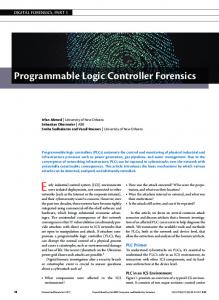
Figure 4 shows a comparison of average output corruption between different logic encryption strategies for K = 128. We can observe that the proposed encryption technique produces comparable output corruption for wrong keys with respect to the fault analysis based approaches [3], whereas the output corruption of strong logic locking [4] is relatively low. As the proposed encryption technique focuses only on the placements of the key-gates, we found that the synthesized encrypted netlists produce the similar area, power, and delay overheads compared to the conventional logic encryption strategies [2]– [4]. Due to the space constraints, we could not show these comparison results. V. D ISCUSSION In this section, we perform a comparative study between different logic encryption strategies with respect to their hardware overhead, output corruptibility, and ability to thwart different state-of-the-art attacks. Table II shows a qualitative comparison between different popular logic encryption techniques. We can observe that all the state-of-the-art logic 978-1-5386-4881-0/18/$31.00 ©2018 IEEE
% Output Corruption
80
Proposed Method Fault Analysis (XOR) [3] Fault Analysis (MUX) [3] Strong Logic Locking [4]
60
40
20
17
84
84 s3
50
85 s3
07
58 s1
4
32 s1
8 37
23 s9
49
4 s5
s1
48
8
0
s1
6 of the table report the number of logic elements (Gstrong ) present in the largest overlapping input cone of dependency (ICODoverlap ) and the number of outputs (Ooverlap ) getting affected by this ICODoverlap , respectively. For example, out of 20679 logic elements of the benchmark s38584, 18272 belong to the ICODoverlap . 268 outputs (out of the total of 304 outputs) are reachable from each of this 18272 logic elements. These 18272 logic elements do not propagate to any other outputs apart from these 268 outputs. For each of the benchmarks, we apply 10000 random patterns to the netlist and analyze the fault impact of each gate of Gstrong using the fault simulator HOPE [9]. Next, we select 200 locations with the highest values of fault impact metric and find their dependency corresponding to each of the Ooverlap outputs. Finally, we pick up 128 locations with the best dependency and encrypt them. While calculating the dependency, we consider the dependency of a key-gate corresponding to all the outputs it affects and finally report the maximum and minimum dependency in columns 7 and 8 of the Table I, respectively. The minimum dependency value of a circuit indicates the minimum effort of brute-force attack (in the power of 2) required to sensitize any key-gate to the output. For example, in circuit s38584, at least 118 other key-bits need to be known to sensitize one key to the output, which requires a brute force search of the order 2(118+#primary inputs) . This is practically infeasible. Thus our proposed method can efficiently prevent path sensitization attack without having one to one dependency among each pair of the key-gates. This relaxation in the dependency criteria helps us to find enough locations to insert the key-gates in a circuit. Table I: Details of different benchmark circuits and final inter-dependency among the keys in our proposed encryption scheme (K = 128)
Figure 4: Comparison of average output corruption between different logic encryption strategies for K = 128 encryption techniques are either vulnerable to at least one of the attacks or produce poor output corruption for wrong keys. Only the External Key-Dependency based approach [11] can thwart all the attacks as well as offers high output corruption for wrong keys. However, this method integrates an external key-permutation unit to introduce dependency among the keys, which costs four times hardware overhead compared to the conventional XOR/XNOR based logic encryption. On the contrary, our proposed key-gate placement strategy can provide the same advantages at the cost of only K XOR/XNOR gates. Table II: A comparative study between different logic encryption strategies Encryption Technique
Random [2]
Fault Analysis (FA) (XOR-based) [3] Fault Analysis (MUX-based) [3] Strong Logic Locking (SLL) [4] Obfuscation Cell (OC) [6] Logic Cone Prevention [8] External Key-Dependency [11] Proposed method
Resilience Against Different Attacks Logic Path Sensitization [4] Cone [8]
Output Corruptibility
×
×
Low
×
×
High
×
×
High
×
Low
×
Low
×
×
Low
High
High
Hardware overhead (K-bit key) K XOR/ (XNOR + NOT) K XOR/ (XNOR + NOT)
K MUX
K XOR/ (XNOR + NOT) K MUX + K NOT K (MUX + XOR/XNOR) 4K XOR/ (XNOR+NOT) K XOR/ (XNOR + NOT)
Recently, a powerful SAT attack has been proposed in [12], which uses an SAT-based algorithm to extract the keys of a logically encrypted combinational circuit. It is worth mentioning that all the above-mentioned logic encryption strategies including ours are vulnerable to SAT attack. However, unlike other attacks, the complexity of SAT attack does not depend on the locations of the key-gates. As the primary focus of this work is to prevent the attacks whose complexity highly depend on the locations of the key-gates, we do not address SAT attack in our work. Fortunately, several countermeasures against SAT attack have already been proposed in the recent times [13]–[15]. These countermeasures require extra hardware infrastructures to be integrated with the conventional logic encryption techniques. Such SAT preventive infrastructures can also be integrated with our proposed strategy to thwart SAT attack. VI. C ONCLUSION In this paper, we have proposed an efficient logic encryption strategy which focuses on finding the best locations to insert the key-gates to thwart different state-of-the-art attacks. The proposed strategy satisfies all the fundamental criteria of a robust logic encryption, which is the most significant advantage over the existing logic encryption solutions, which fail to prevent all the attacks and simultaneously offer high output corruption for wrong keys.
R EFERENCES [1]
[2] [3]
[4]
[5]
[6]
[7]
[8] [9]
[10] [11]
[12] [13] [14] [15]
“Innovation is at risk: Losses of up to $4 billion annually due to ip infringement,” SEMI. [Online]. Available: http://semi.org/en/innovationrisk-losses-4-billion-annually-due-ip-infringement J. A. Roy, F. Koushanfar, and I. L. Markov, “Epic: Ending piracy of integrated circuits,” in DATE, 2008, pp. 1069–1074. J. Rajendran, H. Zhang, C. Zhang, G. S. Rose, Y. Pino, O. Sinanoglu, and R. Karri, “Fault analysis-based logic encryption,” IEEE Tran. on Computers, vol. 64, no. 2, pp. 410–424, 2015. M. Yasin, J. Rajendran, O. Sinanoglu, and R. Karri, “On improving the security of logic locking,” IEEE Tran. on Computer-Aided Design of Integrated Circuits and Systems, no. 99, pp. 1–1, 2015. S. Dupuis, P.-S. Ba, G. Di Natale, M.-L. Flottes, and B. Rouzeyre, “A novel hardware logic encryption technique for thwarting illegal overproduction and hardware trojans,” in (IOLTS), 2014, pp. 49–54. J. Zhang, “A practical logic obfuscation technique for hardware security,” IEEE Tran. on Very Large Scale Integration (VLSI) Systems, vol. 24, no. 3, pp. 1193–1197, 2016. R. Karmakar, S. Chattopadhyay, and R. Kapur, “Enhancing security of logic encryption using embedded key generation unit,” in ITC-Asia. IEEE, 2017. Y.-W. Lee and N. A. Touba, “Improving logic obfuscation via logic cone analysis,” in (LATS). IEEE, 2015, pp. 1–6. H. K. Lee and D. S. Ha, “Hope: An efficient parallel fault simulator for synchronous sequential circuits,” IEEE Tran. on CAD of Integrated Circuits and Systems, vol. 15, no. 9, pp. 1048–1058, 1996. C. Albrecht, “Iwls 2005 benchmarks,” in International Workshop for Logic Synthesis (IWLS): http://www. iwls. org, 2005. R. Karmakar, N. Prasad, S. Chattopadhyay, R. Kapur, and I. Sengupta, “A new logic encryption strategy ensuring key interdependency,” in VLSID. IEEE, 2017, pp. 429–434. P. Subramanyan, S. Ray, and S. Malik, “Evaluating the security of logic encryption algorithms,” in HOST, 2015, pp. 137–143. M. Yasin, B. Mazumdar, J. J. Rajendran, and O. Sinanoglu, “Sarlock: Sat attack resistant logic locking,” in HOST. IEEE, 2016, pp. 236–241. Y. Xie and A. Srivastava, “Mitigating sat attack on logic locking,” IACR Cryptology ePrint Archive, vol. 2016(590), 2016. M. Yasin, A. Sengupta, B. C. Schafer, Y. Makris, O. Sinanoglu, and J. J. Rajendran, “What to lock?: Functional and parametric locking,” in GLSVLSI. ACM, 2017, pp. 351–356.
978-1-5386-4881-0/18/$31.00 ©2018 IEEE