specified input vectors) that should be avoided during test ... Therefore, the fault h stuck-at 0 is ... input cubes to be avoided is applied before test generation.
On Test Generation by Input Cube Avoidance Irith Pomeranz1 School of Electrical & Computer Eng. Purdue University W. Lafayette, IN 47907, U.S.A.
Abstract Test generation procedures attempt to assign values to the inputs of a circuit so as to detect target faults. We study a complementary view whereby the goal is to identify values that should not be assigned to inputs in order not to prevent faults from being detected. We describe a procedure for computing input cubes (or incompletely specified input vectors) that should be avoided during test generation for target faults. We demonstrate that avoiding such input cubes leads to the detection of target faults after the application of limited numbers of random input vectors. This indicates that explicit test generation is not necessary once certain input values are precluded. Potential uses of the computed input cubes are in a test generation procedure to reduce the search space, and during built-in test generation to preclude input vectors that will not lead to the detection of target faults.
1. Introduction Test generation procedures of all types [1]-[12], including deterministic [1]-[6] and directed-search test generation procedures [7]-[12], attempt to assign values to the inputs of the circuit so as to detect target faults. For example, deterministic test generation procedures select appropriate values for the inputs so as to satisfy fault activation and propagation objectives, which are specified as values that need to be assigned to circuit lines in order to detect a target fault. Some procedures for identifying undetectable and redundant faults [13]-[18] search for conditions that are necessary for fault detection, but cannot be satisfied by any assignment to the primary inputs. For example, if a circuit line g is such that setting g = 0 and g = 1 both imply that a line h is set to 0, there is no input assignment that will set h = 1. Therefore, the fault h stuck-at 0 is undetectable. In all these procedures, the focus is on input values that are needed to detect target faults. In this work we study a complementary view for test generation. According to this view, the goal of test generation is to identify values that should not be assigned to inputs in order not to prevent target faults from being detected. The result of the 1. Research supported in part by SRC Grant No. 2004-TJ-1244. 2. Research supported in part by SRC Grant No. 2004-TJ-1243.
978-3-9810801-2-4/DATE07 © 2007 EDAA
and
Sudhakar M. Reddy2 Electrical & Computer Eng. Dept. University of Iowa Iowa City, IA 52242, U.S.A.
proposed procedure is input cubes (or incompletely specified input vectors) that should be avoided during test generation for certain target faults. Suppose that an input cube ci is computed, which prevents the detection of a subset of target faults Fi . During test generation for faults in Fi , the inputs specified under ci should be assigned values that are the complements of the values assigned to them under ci . This restricts the search space during test generation to inputs that are unspecified under ci . For deterministic test generation, it reduces the worst-case complexity of test generation from being proportionate to 2n , where n is the number of inputs, to 2m , where m is the number of inputs unspecified under ci . For randomized procedures, instead of having 2n candidate input vectors, the search can concentrate on 2m candidate vectors when ci is considered. During built-in test generation, the input cubes can be used to impose certain values that will ensure that the detection of target faults is not prevented. A different application where certain cubes are avoided is in the generation of pseudo-functional scanbased tests [19]. In this application, state cubes are avoided in order to reduce/avoid the use of non-functional operation conditions during test. In the procedure proposed here, input cubes are avoided in order to allow/facilitate generation of tests to detect target faults. SAT-based test generation procedures also use what are called conflict-induced clauses [20] in order to avoid assignments that will result in conflicts. However, these clauses are identified during the test generation process, and their derivation thus has worst-case exponential time complexity. The procedure proposed here for deriving input cubes to be avoided is applied before test generation starts, it is suitable for structural test generation, and it has polynomial time complexity. In addition, similar to other test generation procedures, SAT-based test generation procedures also focus on assigning values to the inputs of the circuit so as to detect target faults. We consider full-scan circuits in this work. We define input cubes that should be avoided during test generation for target faults by starting from input cubes where a single input is specified. Such input cubes are called basic input cubes. A circuit with n inputs has 2n basic input cubes (each input can be assigned the value 0 or 1 in order to define a basic input cube). For every basic cube ci , we find a set of faults Fi that cannot be detected under
ci . The set Fi is found based on fault activation and fault propagation conditions that ci prevents from being satisfied. We combine basic input cubes in order to obtain input cubes with more specified inputs. The combination of basic input cubes is guided by considering specific target faults. For example, for a four-input circuit, if both 0xxx and x0xx prevent the detection of a fault f , 00xx should be avoided during test generation for f . In this case, 0xxx and x0xx are combined into 00xx based on f . The complexity of computing input cubes that need to be avoided is polynomial in the circuit size. Specifically, the computation of basic cubes is linear in the circuit size. For N basic cubes and M faults, at most NM input cube combinations are performed. In the test generation experiment we report to demonstrate the effectiveness of the computed cubes, for every input cube ci computed by the proposed procedure, we apply a limited number of input vectors that avoid the values specified by ci (these values would have prevented the target faults in a set Fi from being detected). Inputs that are unspecified under ci are assigned random values. The results of this experiment demonstrate that it is sufficient to avoid the values specified under ci in order to detect the faults in Fi after a limited number of input vectors are applied. Thus, conventional test generation that attempts to assign values so as to detect the faults directly is either unnecessary or has a reduced complexity when ci is used to avoid certain values. It is possible to extend this concept to synchronous sequential circuits by defining primary input vectors that should be avoided during test generation based on the ability of input cubes to synchronize state variables of the circuit. We do not consider this issue in this work. The paper is organized as follows. The computation of basic cubes, and the computation of additional cubes by considering target faults, are described in Section 2. In Section 3 we describe a test generation experiment aimed at demonstrating that avoiding the computed input cubes facilitates the detection of target faults. Experimental results are presented in Section 4.
2. Computing cubes In this section we describe the computation of input cubes that should be avoided during test generation for target faults. We first describe the computation of basic input cubes where a single input is specified. We then describe the computation of additional input cubes from the basic ones. We denote the number of circuit inputs by n , and the inputs by a 0,a 1, . . . ,an −1.
2.1. Basic input cubes A basic input cube is an input cube where one input is specified to 0 or 1, and the remaining inputs are unspecified. For example, for a three-input circuit, the
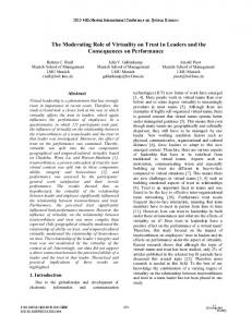
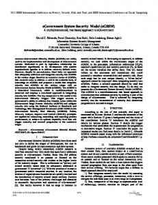
basic cubes are 0xx, 1xx, x0x, x1x, xx0 and xx1, where x is an unspecified value. We denote the basic input cube where input a j is specified to the value v by c (a j =v ). We denote by F (a j =v ) the set of faults whose detection will be prevented by c (a j =v ). To find F (a j =v ), we apply the following procedure. We assign c (a j =v ) to the inputs of the circuit, and compute the values throughout the circuit. The fault line g stuck-at w is prevented from being detected if one of the following conditions is satisfied. (1) g = w under c (a j =v ). In this case, the fault cannot be activated (activation requires g = w′ in the fault free circuit). (2) g = x under c (a j =v ), but there is no x-path from g to an output. An x-path is a path such that all the lines along the path have unspecified values assigned to them. Without an x-path to an output, it may be possible to activate f by assigning g = w′ in the fault free circuit and g = w in the faulty circuit; however, it is impossible to propagate the difference to a primary output. For illustration, we show in Figure 1 a circuit under the input cube c (a 0=0). The faults a 0 stuck-at 0 and g 1 stuck-at 0 cannot be detected since they cannot be activated under this cube. The faults a 1 stuck-at 0 and a 1 stuck-at 1 cannot be detected since a 1 does not have an x-path to the output under this input cube. We obtain a set F (a 0=0) that consists of the above four faults. a 0=0 g 1=0 a 1=x & +
g 3=x
a 2=x g 2=x a 3=x & Figure 1: Example of a basic cube We point out that it may be possible to identify additional faults as being prevented from detection under c (a j =v ). However, this requires additional analysis of the circuit, which would be more time consuming. In our experiments we compute F (a j =v ) as above, using only simple implications of c (a j =v ). For every input a j , where 0 ≤ j < n , and for every value v , where v ∈ {0,1}, we define a basic input cube c (a j =v ), and we compute the set of faults F (a j =v ) whose detection is prevented under c (a j =v ). We include c (a j =v ) in the set of basic cubes denoted by C 1 if F (a j =v ) ≠ φ. The construction of C 1 is summarized in Procedure 1 next. Procedure 1: Finding the basic set of cubes C 1 (1) Set C 1 = φ. Let F be the set of target faults. (2) For every input a j where 0 ≤ j < n and for every value v ∈ {0,1}:
(a)
(b)
(c)
Let c (a j =v ) be the input cube where a j = v and all the other inputs are unspecified. Assign c (a j =v ) to the inputs of the circuit and compute the values throughout the circuit. Find all the lines with x-paths to the primary outputs. Set F (a j =v ) = φ. For every fault f ∈ F : Let f be the fault line g stuck-at w . If g = w , or g = x and there is no x-path from g to an output, add f to F (a j =v ). If F (a j =v ) ≠ φ, add c (a j =v ) to C 1.
2.2. Additional input cubes Starting from C 1, we generate additional input cubes based on target faults. We denote the cube computed for a fault f k by c (f k ), and the set of cubes computed based on all the target faults by C 2. Although we compute C 2 by considering all the target faults, it is possible to consider subsets of faults (or one fault at a time) in order to avoid storage of the complete set. We first demonstrate the computation of C 2 using the example shown in Table 1. The example is based on ISCAS-89 benchmark circuit s 27. The circuit has seven inputs and 32 stuck-at faults. Table 1 shows all the basic cubes that prevent the detection of at least one fault. These cubes form the set C 1. In every case we show the cube c (a j =v ) and the set of faults F (a j =v ) whose detection is prevented by c (a j =v ). We renumber the basic cubes in C 1 as c 1,c 2, . . . ,c 14. The set of faults whose detection is prevented by ci is denoted by Fi . Table 1: Basic cubes for s 27 � � Fi ci �i������������������������������������� 1 � 0xxxxxx � f 7 f 13 f 25 f 28 2 � 1xxxxxx � f 4 f 6 f 12 f 14 f 18 f 19 � � 3 � x0xxxxx � f 0 4 � x1xxxxx � f 5 f 8 f 10 f 11 5 � xx0xxxx � f 1 6 � xx1xxxx � f 10 f 16 7 � xxx0xxx � f 2 8 � xxx1xxx � f 18 f 21 9 � xxxx0xx � f 3 10 � xxxx1xx � f 2 f 4 f 11 f 13 f 14 f 15 f 18 f 19 � � f f f f f f f � � 20 21 22 23 25 26 31 11 � xxxxx0x � f 13 f 14 f 18 f 19 12 � xxxxx1x � f 4 13 � xxxxxx0 � f 5 14 � xxxxxx1 � f 0 f 8 f 10 f 11
We set C 2 = φ. Considering every target fault, the cubes described below are added to C 2. All the cubes added to C 2 are shown in Table 2. They are numbered c 15,c 16, . . . . The fault f 0 is included in F 3 and F 14. This implies that c 3 = x0xxxxx and c 14 = xxxxxx1 prevent the detection of f 0. Combining c 3 and c 14, we obtain the cube c (f 0) = x0xxxx1 that also prevents the detection of f 0.
We add c (f 0) to C 2 and denote it by c 15. From F 3 ∩ F 14 = {f 0} we conclude that the detection of other faults in F 3 and F 14 is prevented by c 3 and c 14 separately. For example, the remaining faults in F 14 are f 8, f 10 and f 11, and their detection is prevented by c 14 alone. In order not to overestimate the values that need to be avoided in order to detect these faults, we do not count them as prevented from being detected by c 15. Based on this discussion, we set F 15 = F 3 ∩ F 14 = {f 0}. The fault f 1 is included only in F 5. Therefore, no new cubes are created based on f 1 beyond those already included in C 1. For f 2 we obtain c 16 = xxx01xx by combining c 7 and c 10. We obtain F 16 = F 7 ∩ F 10 = {f 2}. Skipping over several faults, we consider f 8 next. The fault f 8 is included in F 4 and in F 14. Therefore, both c 4 = x1xxxxx and c 14 = xxxxxx1 prevent the detection of f 8. Combining c 4 and c 14, we obtain the cube c (f 8) = x1xxxx1 that prevents the detection of f 8. We add c (f 8) to C 2 as c 19. From F 4 ∩ F 14 = {f 8, f 10, f 11} we conclude that the detection f 10 and f 11 is also prevented by every value specified under c (f 8). Therefore, these faults should be included in F 19. The detection of other faults in F 4 and F 14 is prevented by c 4 and c 14 separately. Therefore, we do not count these faults as prevented from being detected by c 19. We obtain F 19 = F 4 ∩ F 14 = {f 8, f 10, f 11}. The fault f 9 is not included in any set Fi of a cube ci ∈ C 1. No new cube is generated based on this fault. The fault f 14 is included in F 2, F 10 and F 11. Combining c 2 = 1xxxxxx, c 10 = xxxx1xx and c 11 = xxxxx0x, we obtain the cube c (f 14) = 1xxx10x that prevents the detection of f 14. We add c (f 14) to C 2 as c 23. We set F 23 = F 2 ∩ F 10 ∩ F 11 = {f 14, f 18, f 19}. In general, for a fault f k , we compute a cube c (f k ) by combining all the cubes ci ∈ C 1 such that f k ∈ Fi . We then compute the set of faults whose detection is prevented by c (f k ) as F (f k ) = ∩ {Fi :f k ∈ Fi }. If f k does not appear in any set Fi , we obtain the all-x cube for c (f k ), and we do not add this cube to C 2. If f k appears in a single set Fi , c (f k ) = ci is already included in C 1, and we do not add it to C 2. Finally, if f k ∈ Fi 1, f k ∈ Fi 2, and ci 1 and ci 2 assign opposite values to the same input, f k is undetectable. In the example of s 27, the set of cubes C 2 obtained by this process is shown in Table 2. The procedure for computing C 2 from C 1 is given next as Procedure 2. Procedure 2: Finding the set of cubes C 2 from C 1 (1) Set C 2 = φ. (2) For every target fault f k : (a) Compute the cube c (f k ) obtained by combining all the cubes ci ∈ C 1 such that f k ∈ Fi .
Table 2: C 2 for s 27 � Fi i � ci ������������������������ 15 � x0xxxx1 � f 0 16 � xxx01xx � f 2 � � 17 � 1xxx11x � f 4 18 � x1xxxx0 � f 5 19 � x1xxxx1 � f 8 f 10 f 11 20 � x11xxx1 � f 10 21 � x1xx1x1 � f 11 22 � 0xxx10x � f 13 23 � 1xxx10x � f 14 f 18 f 19 24 � 1xx110x � f 18 25 � xxx11xx � f 18 f 21 � � 26 � 0xxx1xx � f 13 f 25
(b)
Compute the set of faults whose detection will be prevented by c (f k ) as F (f k ) = ∩ {Fi :f k ∈ Fi }. (c) If c (f k ) ∈ / C 1 and c (f k ) is not the all-x cube, add c (f k ) to C 2. It is interesting to see the results of Procedures 1 and 2 when applied to a circuit consisting of a single AND gate with a large number of inputs. Such a circuit is difficult to test using random input vectors. For example, consider the stuck-at 1 fault on the first input of an eightinput AND gate. Its detection is prevented by the cube 1xxxxxxx (which prevents activation of the fault), as well as by the cubes x0xxxxxx, xx0xxxxx, xxx0xxxx, xxxx0xxx, xxxxx0xx, xxxxxx0x and xxxxxxx0 (which block all the x-paths from the fault site to the output). When these cubes are combined based on the fault, the cube 1000000 results. The complement cube, 01111111, is a test for the fault (the rationale for using the complement is discussed in the next section).
3. Test generation experiment The cubes in C 1 and C 2 are computed such that there are target faults whose detection will be prevented by these cubes. To allow these faults to be detected, each cube must be prevented from appearing during the test generation process for the corresponding faults. A cube ci is prevented from appearing by complementing each specified value in ci . Suppose that ci is obtained by combining a subset of basic cubes {c (a j =v j )}. Each assignment a j = v j alone is sufficient for preventing the detection of the faults in Fi . Therefore, all the specified inputs of ci must be complemented in order to allow the faults to be detected. We denote the cube obtained by complementing every specified bit of ci by c�i . For example, for c 19 = x1xxxx1 of s 27, we obtain c�19 = x0xxxx0. During test generation for the faults in F 19, we must set a 1 = 0 and a 6 = 0 in order to allow the faults in F 19 to be detected. Given a set of input cubes C = {c 0,c 1, . . . ,cN −1} to be avoided, the test generation process we use to demonstrate the effectiveness of avoiding input cubes in C
proceeds as described next. If C is computed based on a subset of faults in order to avoid storage of a large set of cubes, the test generation process should be repeated using additional sets of cubes for yet-undetected faults. The test generation process starts from a set of target faults denoted by F . We apply to the circuit a set T = {t 0,t 1, . . . ,tR −1} of R random input vectors, for a constant R . We apply each input vector t j ∈ T under a different input cube ci ∈ C . When an input vector t j ∈ T is applied under a cube ci ∈ C , c�i is imposed on top of t j in order to allow the faults in Fi to be detected. We rotate through the cubes in C as the input vectors in T are applied. For example, for a circuit with four inputs and R = 10, suppose that the set of random input vectors T shown in the second column of Table 3 is used. Suppose that C consists of three input cubes, c 0 = 0xxx, c 1 = x0xx and c 2 = xx11. We impose c�0 on t 0, c�1 on t 1, c�2 on t 2, c�0 on t 3, and so on. The resulting input vectors are shown in the three rightmost columns of Table 3. Thus, 1011 is applied instead of t 0 = 0011 based on c 0, t 1 = 1101 is applied unmodified based on c 1, 0000 is applied instead of t 2 = 0010 based on c 2, and so on. Table 3: Random input vectors � tj � 0xxx � x0xx � xx11 �j ���������������������������� � 0 � 0011 � 1011 � � 1101 � 1 � 1101 � � � � � 2 � 0010 � � � 0000 3 � 0011 � 1011 � � 4 � 1110 � � 1110 � 5 � 0011 � � � 0000 6 � 1011 � 1011 � � � 0101 � 7 � 0001 � � � 1000 8 � 1010 � 9 �� 0110 �� 1110 �� ��
As input vectors are applied, target faults may be detected and dropped from the set of target faults F . When all the faults in Fi , whose detection is prevented by a cube ci ∈ C , are already detected, it is possible to stop using ci during the test generation process. In this case, more input vectors would be applied under the remaining cubes, enhancing the ability to detect the remaining faults. For example, suppose that in the example of Table 3, all the faults in F 0 become detected after t 3 is applied under c 0. For t 4,t 5, . . . , only c 1 and c 2 are used in this case. The resulting test set is shown in Table 4. The random test generation process described above is summarized in Procedure 3 next. Procedure 3: Random test generation (1) Let F be the set of target faults. Let C be a set of input cubes of size N . Set i = 0 and j = 0. (2) If Fi ∩ F ≠ φ: (a) Impose c�i on the random input vector t j and perform fault simulation of the resulting vector under F with fault dropping. If F = φ, stop.
Table 4: Random input vectors with cube dropping � tj � 0xxx � x0xx � xx11 �j ���������������������������� � 0 � 0011 � 1011 � � 1101 � 1 � 1101 � � � � � 2 � 0010 � � � 0000 3 � 0011 � 1011 � � 4 � 1110 � � 1110 � 5 � 0011 � � � 0000 6 � 1011 � � 1111 � � � 0000 7 � 0001 � � 1110 � 8 � 1010 � �� �� 0100 9 �� 0110 ��
(b) Set j = j +1. If j = R , stop. Set i = i +1. If i = N , set i = 0. Go to Step 2. We define the set of cubes C to be avoided during test generation as follows. We define a set of cubes C 0 that consists of a single all-x cube, denoted by c 0. When this cube is used, random input vectors are applied unmodified to the circuit. We define F 0 = F for this cube to ensure that it is used throughout the test generation process. We use Procedures 1 and 2 to compute C 1 and C 2, respectively. We then define C = C 0∪C 1∪C 2. (3)
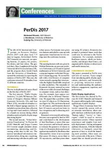
4. Experimental results We applied the random test generation process described in Section 3 to the following circuits. (1) A circuit comprised of an n -input AND gate, for n = 32 and 64. (2) Multi-level implementations of Berkeley PLAs. (3) Irredundant versions of the combinational logic of ISCAS-89 benchmark circuits. For all these circuits, 100% fault coverage can be achieved for single stuck-at faults. For a circuit with n inputs, we use R = 100n , 500n , 1000n , 2000n and 5000n . We only report the results when R random input vectors, applied unmodified for any value of R considered, do not achieve 100% fault coverage. We stop increasing R when 100% fault coverage is achieved by Procedure 3. Using random vectors, inordinately large numbers of vectors are required to achieve 100% fault coverage for the circuits considered. The results are shown in Table 5. After the circuit name we show the number of inputs and the number of faults. Under column R we enter the value of R as p .n , where p = 100, 500, 1000, 2000 or 5000. Under column C =C 0 we show the fault coverage achieved by R random input vectors when they are applied without modification (C = C 0 in Procedure 3). We also show the number of input vectors applied until the final fault coverage is achieved. Under column C =C 0UC 1UC 2, subcolumn cubes we show the number of cubes in C = C 0∪C 1∪C 2. Under subcolumn f .c. we show the fault coverage achieved using the cubes in C = C 0∪C 1∪C 2. Under subcolumn vect we show the number of input vectors applied until the final fault coverage is achieved. It can be seen from Table 5 that for most of the circuits considered, 100% fault coverage is achieved with
R ≤ 5000n when random input vectors are modified so as to avoid values that prevent target faults from being detected. Even when increasing R does not improve the fault coverage achieved by unmodified random input vectors, the additional input vectors applied under the cubes in C = C 0∪C 1∪C 2 allow the fault coverage to increase. The number of cubes in C = C 0∪C 1∪C 2 is much smaller than the number of faults for the larger circuits. In many cases, the number of input vectors applied until the fault coverage reaches its final value is smaller under C = C 0∪C 1∪C 2 than when the input vectors are applied without modification under C = C 0.
5. Concluding remarks We described a procedure for computing input cubes that should be avoided during test generation for target faults. Such input cubes either prevent a fault from being activated, or block its propagation by blocking all the x-paths to the outputs. The input cubes were computed in polynomial time by first computing basic cubes in linear time, and then combining basic cubes based on target faults. The input cubes can be used by a test generation procedure to reduce the search space, or during builtin test generation to preclude input vectors that will not lead to the detection of a target fault. We described an experiment were the input cubes were used during random test generation to modify the input vectors applied to the circuit. The result was 100% fault coverage for most of the circuits where pure random input vectors achieve a much lower fault coverage. The faults were detected by applying limited numbers of input vectors based on every input cube, indicating that it is sufficient to avoid a situation where a fault is prevented from being detected in order to detect a fault, and direct test generation for the fault can be avoided.
References [1]
[2]
[3]
[4]
[5]
[6]
P. Goel and B. C. Rosales, "Test Generation and Dynamic Compaction of Tests", in Proc. Test Conf., 1979 pp. 189192. I. Pomeranz, L. N. Reddy and S. M. Reddy, "COMPACTEST: A Method to Generate Compact Test Sets for Combinational Circuits", in Proc. Intl. Test Conf., 1991, pp. 194-203. J.-S. Chang and C.-S. Lin, "Test Set Compaction for Combinational Circuits", in Proc. Asian Test Symp., 1992, pp. 20-25. Y. Matsunaga, "MINT -An Exact Algorithm for Finding Minimum Test Sets", IEICE Trans. Fundamentals., vol. E76-A, No. 10, Oct. 1993, pp. 1652-1658. S. Kajihara, I. Pomeranz, K. Kinoshita and S. M. Reddy, "Cost-Effective Generation of Minimal Test Sets for Stuck-at Faults in Combinational Logic Circuits", IEEE Trans. on Computer-Aided Design, Dec. 1995, pp. 14961504. I. Hamazaoglu and J. H. Patel, "Test Set Compaction Algorithms for Combinational Circuits", in Proc. Intl.
[7] [8]
[9]
[10]
[11]
[12]
[13]
Conf. on Computer-Aided Design, 1998, pp. 283-289. J. Snethen, "Simulation-Oriented Fault Test Generator", in Proc. Design Autom. Conf., 1977, pp. 88-93. V. D. Agrawal, K. T. Cheng, and P. Agrawal, "A Directed Search Method for Test Generation Using Concurrent Simulator," IEEE Trans. on Computer-Aided Design, Feb. 1989, pp. 131-138. D. G. Saab, Y. G. Saab and J. A. Abraham, "CRIS: A Test Cultivation Program for Sequential VLSI Circuits," in Proc. Intl. Conf. on Computer-Aided Design, 1992, pp. 216-219. E. M. Rudnick, J. H. Patel, G. S. Greenstein and T. M. Niermann, "Sequential Circuit Test Generation in a Genetic Algorithm Framework", in Proc. Design Autom. Conf., 1994, pp. 698-704. P. Prinetto, M. Rebaudengo and M. Sonza Reorda, "An Automatic Test Pattern Generator for Large Sequential Circuits based on Genetic Algorithms", in Proc. Intl. Test Conf., 1994, pp. 240-249. I. Pomeranz and S. M. Reddy, "On Improving Genetic Optimization based Test Generation", in Proc. European Design & Test Conf., 1997, pp. 506-511. M. A. Iyer and M. Abramovici, "Sequentially Untestable Faults Identified Without Search (Simple Implications Beat Exhaustive Search!)", in Proc. Intl. Test Conf., 1994, pp. 457-462.
Table 5: Experimental results
[14]
[15]
[16]
[17]
[18]
[19]
[20]
D. E. Long, M. A. Iyer and M. Abramovici, "Identifying Sequentially Untestable Faults Using Illegal States", in Proc. VLSI Test Symp., 1995, pp. 4-11. M. A. Iyer, D. E. Long, and M. Abramovici, "Identifying Sequential Redundancies Without Search", in Proc. Design Autom. Conf., 1996, pp. 457-462. X. Lin, I. Pomeranz and S. M. Reddy, "On Finding Undetectable and Redundant Faults in Synchronous Sequential Circuits", in Proc. Intl. Conf. on Computer Design, 1998, pp. 498-503. P. Qiang, M. Abramovici and J. Savir, "MUST: Multiple-Stem Analysis for Identifying Sequentially Untestable Faults", in Proc. Intl. Test Conf., 2000, pp. 839-846. M. Syal and M. S. Hsiao, "Untestable Fault Identification Using Recurrence Relations and Impossible Value Assignments", in Proc. VLSI Design Conf., 2004, pp. 481-486. Y.-C. Lin, F. Lu, K. Yang and K.-T. Cheng, "Constraint Extraction for Pseudo-Functional Scan-Based Delay Testing", in Proc. Asia and South Pacific Design Autom. Conf., 2005, pp. 166-171. J. P. Marques-Silva and K. A. Sakallah, "GRASP: A Search Algorithm for Propositional Satisfiability", IEEE Trans. on Computers, May 1999, pp. 506-521.
� � � C = C0 � C = C0 U C1 U C2 � inp � f.c. circuit faults � R vect � cubes f.c. vect ������������������������������������������������������������������������� and32 � 32 34 � 100n � 2.94 1 � 98 100.00 98 ������������������������������������������������������������������������� � � � � and64 64 66 � 100n � 1.52 1 � 194 100.00 194 ������������������������������������������������������������������������� � rckl 32 367 � 100n � 39.24 2488 � 332 99.73 2843 � rckl � 32 367 � 500n � 51.50 14461 � 332 100.00 4556 ������������������������������������������������������������������������� � vg2 25 200 � 100n � 98.00 1404 � 156 100.00 309 ������������������������������������������������������������������������� � x1dn 27 198 �� 100n �� 87.37 1666 �� 159 99.49 574 � x1dn 27 198 � 500n � 89.39 7323 � 159 99.49 574 � x1dn 27 198 � 1000n � 90.40 17300 � 159 100.00 16576 ������������������������������������������������������������������������� � x9dn � 27 225 � 100n � 88.44 1430 � 156 99.11 466 � x9dn 27 225 � 500n � 93.33 9501 � 156 99.11 466 � x9dn 27 225 � 1000n � 94.22 20573 � 156 99.11 466 � x9dn 27 225 � 2000n � 98.67 49680 � 156 100.00 49680 ������������������������������������������������������������������������� � � � � s420 35 336 � 100n � 89.58 3111 � 277 100.00 505 ������������������������������������������������������������������������� � s641 54 381 � 100n � 97.90 3291 � 318 100.00 792 ������������������������������������������������������������������������� � � s820 23 684 � 100n � 94.01 2288 � 577 100.00 617 ������������������������������������������������������������������������� � s953 45 811 � 100n � 94.08 3903 � 503 100.00 906 ������������������������������������������������������������������������� � � � � s1423 91 1126 � 100n � 99.56 4717 � 555 100.00 4873 ������������������������������������������������������������������������� � s5378 4010 � 100n � 99.58 21017 � 1544 100.00 8602 ������������������������������������������������������������������������� � 214 � 247 s9234 4666 � 100n � 92.88 24589 � 1686 97.49 24469 � 247 s9234 4666 � 500n � 96.44 113714 � 1686 99.38 122635 � 247 s9234 4666 � 1000n � 96.61 128271 � 1686 99.81 223786 � � � � s9234 247 4666 � 2000n � 96.61 128271 � 1686 99.96 424136 � s9234 4666 � 5000n � 96.61 128271 � 1686 100.00 545479 ������������������������������������������������������������������������� � 247 s13207 � 699 8371 � 100n � 99.76 68312 � 3172 100.00 62136 ������������������������������������������������������������������������� s15850 � 611 9620 � 100n � 96.47 59264 � 3157 99.77 58449 s15850 � 611 9620 � 500n � 97.02 125633 � 3157 100.00 96963 ������������������������������������������������������������������������� s38417 �� 1664 25261 �� 100n �� 98.23 129753 �� 8504 99.51 164487 s38417 � 1664 25261 � 500n � 98.23 129753 � 8504 99.76 713186 s38417 � 1664 25261 � 1000n � 98.23 129753 � 8504 99.89 1659710 s38417 � 1664 25261 � 2000n � 98.23 129753 � 8504 99.98 2288368 s38417 � 1664 25261 � 5000n � 98.23 129753 � 8504 99.98 2288368 ������������������������������������������������������������������������� s38584 � 1455 30725 � 100n � 99.83 102554 � 12024 99.93 122207 s38584 � 1455 30725 � 500n � 99.83 102554 � 12024 99.98 368537 � � � � s38584 � 1455 30725 � 1000n � 99.83 102554 � 12024 99.98 368537 s38584 � 1455 30725 � 2000n � 99.83 102554 � 12024 99.98 368537 s38584 � 1455 30725 � 5000n � 99.83 102554 � 12024 99.98 368537