IEEE TRANSACTIONS ON COMPUTER-AIDED DESIGN OF INTEGRATED CIRCUITS AND ... Large fan-out gates are associated with heavy capacitive loading.
1170
IEEE TRANSACTIONS ON COMPUTER-AIDED DESIGN OF INTEGRATED CIRCUITS AND SYSTEMS, VOL. 20, NO. 9, SEPTEMBER 2001
�
On the Complexity of Gate Duplication
intrinsic delay from i to output of g ; drive capability or load coefficient of the path from i to the output of g . Let r(g ) denote the required time at the output of a gate g . The following equation illustrates the method of computing r(g ) if the required times of the fan-outs of g are available: i;g
i;g
Ankur Srivastava, Ryan Kastner, and Majid Sarrafzadeh Abstract—In this paper, we show that both the global and local gate duplication problems for delay optimization are NP-complete under certain delay models. Index Terms—Gate duplication, NP-completeness, required time, satisfiability, VLSI.
Large fan-out gates are associated with heavy capacitive loading leading to large delay. Duplication of such gates reduces the number of fan-outs and hence their gate delays. This can potentially reduce the overall circuit delay. In this paper, we address the complexity issues regarding gate duplication for delay optimization. We believe that proofs of NP-completeness (such as the ones we present in this paper) can give usefull directions to algorithm designers [7]. Recently, there has been some work which addresses gate duplication in a delay optimization perspective. Reference [4] discusses a gain based heuristic for improving the circuit delay in the technology independent phase that has been enhanced in [1] and [3] proposes an algorithm to solve the global gate duplication (G-GD) problem in the post technology mapping phase. In this paper, we prove both the G-GD and local gate duplication (L-GD) problems to be intractable. In [6], Lillis provides some formulations for solving this problem. He mentions the NP-completeness of the local problem, but no formal proof is given. As mentioned before, gate duplication reduces the capacitive loading seen at the output. Fan-out optimization by buffer insertion also strives to reduce the capacitive loading. It inserts buffers on the nets driven by the gate, hence, reducing the loading. Although the objective of both the strategies is similar, the methodology used to achieve this objective is different. Hence, these two problems are essentially different. As we show later, complexity results of one do not imply a similar complexity of the other. The rest of the paper is organized as follows. Section II provides an insight into the delay models and the problem of gate duplication. Section III contains the proof for NP-completeness of the G-GD problem. Section IV shows that even the L-GD problem is NP-complete. Section V contains some observations and conclusion. II. PRELIMINARIES A. Delay Models Given a single output gate g , let � (i; g ) denote delay from an input pin i of the gate g to the output of g . The load Cg denotes the cumulative capacitance seen at the output of g . It is the sum of the individual input pin capacitances p for all fan-outs p of g [9]. A commonly used delay model for gate level circuits is the load-dependent delay model (LDDM). The delay in the gate g is given by
where
c
g
i;g
+ i;g cg
min
2F O(g)
x
fr(x) 0 � 0 c g: g;x
g;x x
(2)
B. Gate Duplication Problem
I. INTRODUCTION
� (i; g) = �
r(g) =
(1)
load capacitance at the output of the gate g ;
Manuscript received May 26, 2000; revised March 14, 2001. This paper was recommended by Associate Editor C.-K. Cheng. The authors are with the Computer Science Department, University of California, Los Angeles, CA 90095 USA. Publisher Item Identifier S 0278-0070(01)06894-4.
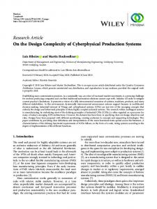
Gate duplication can be used for delay optimization. The idea is illustrated with the following example. We use the LDDM in this example. Consider the circuit shown in Fig. 1(a) in which the parameters � and along with the required times at the gate outputs have been indicated. The subscript i has been omitted as all the gates have just one input pin. We will show that the delay through this circuit can be improved by duplicating some gates. In the unduplicated case [see Fig. 1(a)], the capacitive loading CD = 5+5+5 and CE = 0:1. Hence, the required time at the input of E can be calculated to be 015:1. When D is duplicated [see Fig. 1(b)], the capacitive loading CD = 5 + 5 and CE = 0:2. Hence, the new required time at the input of E becomes 010.2. Gate duplication was hence instrumental in improvement of circuit delay. III. GLOBAL OPTIMIZATION BY GATE DUPLICATION In this section, the G-GD problem is proved NP-complete. The next section proves a similar result for the L-GD problem. Although the proof of NP-completeness of the L-GD problem implies the intractability of the G-GD problem, the proof for G-GD problem is still important. It illustrates that even if the L-GD problem can be solved optimally by exponential enumeration or by using some pseudopolynomial algorithms [6], the G-GD problem is still NP-complete. Moreover, it shows the NP-completeness of the G-GD problem, which is a much stronger result than pure intractability (as implied by the proof of the L-GD problem). The G-GD problem can be defined as follows: 1) given a network � consisting of primary inputs (PIs), primary outputs (POs), internal gates, and nets; 2) given all delay parameters �, , and ; 3) given the required time at the POs; 4) find a duplication strategy that maximizes the minimum required time at the input pin of the PIs. We assume that the PIs and outputs cannot be duplicated. We also assume that we make only two and not multiple copies of a gate. All wire capacitances and delays are considered zero and the circuit has only single output combinational gates. The G-GD problem could be stated as follows Instance: A combinational circuit � with PIs, POs, and gates. Given the required times at the POs and a number D . Question: Does there exist a gate duplication strategy of the gates such that the required time at the input of each PI is at least D ? Theorem: The G-GD problem is NP-complete. Proof: Let us first observe that this problem is in NP. Given the circuit � , the required times at the POs, and a duplication strategy, we can always topologically traverse from the POs to PIs and evaluate the input required times. Then, we can check whether the input required time constraint has been met or not. Hence, given a duplication strategy, the decision could be made in polynomial time. Thus, the problem is in NP.
0278–0070/01$10.00 ©2001 IEEE
IEEE TRANSACTIONS ON COMPUTER-AIDED DESIGN OF INTEGRATED CIRCUITS AND SYSTEMS, VOL. 20, NO. 9, SEPTEMBER 2001
(a)
1171
(b)
Fig. 1. Delay optimization by gate duplication. (a) Original circuit. (b) Circuit after duplication of D.
Fig. 2.
Variable circuit assembly.
In order to prove the NP-completeness, we transform Mono3SAT to an instance of gate duplication problem. Mono3SAT: Set U of variables U = x1 ; x2 ; x3 ; . . . ; xn and a set C of conjunctive clauses C = C1 ; C2 ; C3 ; . . . ; Cm , such that jCj j = 3 and each Cj contains only negated or only unnegated variables [5]. Is there a truth assignment to the n variables that satisfies C ? We transform Mono3SAT to the gate duplication problem. The circuit � that we construct contains two kinds of circuit assemblies: 1) variable circuit assemblies (VCAs) n and 2) clause circuit assemblies (CCAs) m. Fig. 2 shows the circuit assembly for a variable xi . The subscript i has been dropped from the gate parameters as they are the same for all the input pins. In this assembly, we have a PO that cannot be duplicated. The required time at the PO is given to be three. Using the given parameters, rx and rx can be calculated to be one. Gates xi and x0i
correspond to the positive and negative phase of the variable xi . Gate xi has as many inputs as the number of clauses in which the variable appears as a positive phase. Similarly, gate x0i has as many inputs as the number of clauses in which the variable appears as a negative phase. In the final circuit, the gates xi and x0i will be connected to clauses in which the variable appears as positive and negative phase, respectively. Fig. 3 shows the clause circuit assembly. Again, there are two kinds of clause gates. It shows the gates that correspond to a positive and negative phase clause, respectively. In the final circuit, these clause gates will be PIs, so they are not fit for duplication. As mentioned before, these clause gates are the drivers of the input signals. By the definition of Mono3SAT, we cannot have any clauses in which both positive and negative phase variables are present. The final circuit assembly is shown in Fig. 4. There are n POs and m PIs. The positive and negative phase clauses are connected only
1172
IEEE TRANSACTIONS ON COMPUTER-AIDED DESIGN OF INTEGRATED CIRCUITS AND SYSTEMS, VOL. 20, NO. 9, SEPTEMBER 2001
Xi’ gates that have their corresponding variables (not the literal) assigned the value True. Fig. 7(c) indicates the situation when such gates have been duplicated. Again, the required time at the input of PI can be calculated to be
r = 00:2 0
11:2 + 5
3 03:1
=
011:56666:
(4)
(a)
(b) Fig. 3. Clause circuit assembly. (a) Positive phase clause. (b) Negative phase clause.
to the positive and negative phase gates, respectively, of the corresponding VCAs. It must be noted that each clause gate has a fan-out of exactly three. This completes the construction of the circuit � . Let D = 011:57 for this circuit. It is worth noting that this is a polynomial time transformation from Mono3SAT to � . We show that Mono3SAT is satisfiable iff there exists a duplication strategy of the gates such that the required time constraint for all the PIs of � can be met. It can be observed from Fig. 2 that gate Ai can be duplicated. Assignment of False to a variable corresponds to duplicating the gate Ai in the corresponding variable assembly. Similarly, a True assignment corresponds to the case in which this gate is not duplicated. Fig. 5(a) and (b) indicates this truth assignment. The following observations can be made for the above transformation and Table I. When the truth value of a variable is True, then the corresponding positive phase gate (xi ) has a higher required time on the input pin as compared to False. On the contrary, when the variable is True, then the negative phase gate (x0i ) has a lower required time than False. Hence, the required time at the input pin of a gate (positive or negative) is higher when the corresponding variable is assigned a truth value that satisfies the clause gate connected to that gate. Only If: In this section, we prove that if Mono3SAT is satisfiable then there exists a duplication strategy that satisfies the required time constraint. This implies that each clause has at least one literal that evaluates toTrue. Positive phase clause: Fig. 6(a) illustrates the situation in which one of the literals of a positive phase clause is True. As shown in Fig. 6(b) let us duplicate all the Xi gates that evaluate to the truth value of False. Fig. 6(c) indicates the situation when such gates have been duplicated. Using LDDM, the required time at the PI can be calculated to be
r = 06:4 0
0+5
3 33:1
=
011:56666:
(3)
Hence, the required time constraint is met. When there are more than one literals with truth value True, then we can duplicate the gates that have False assigned to the corresponding variables and meet the required constraint. Negative phase clause: Fig. 7(a) illustrates the situation in which one of the literals evaluates to True (i.e., one of the variables has been assigned the value False). As shown in Fig. 7(b), let us duplicate those
This meets the required time constraint. When more than one literal has the truth value of True, a similar duplication strategy can be used to meet the required time constraint. This proves that when there is a truth assignment to variables that satisfies Mono3SAT, there is a duplication strategy that can meet the required time constraint in � . If: In this section, we prove that MONO3SAT is satisfiable if there exists a duplication strategy which meets the input pin required time constraint. First, we need to show that if the input pin required times of all the clause gates are met then for all the positive phase clauses there has to be at least one Ai gate in the corresponding VCAs, which is not duplicated. Also in such a case, for all the negative phase clauses, there has to be at least one Ai gate in the corresponding VCAs which is duplicated. In order to prove this, we first show that in positive phase clause, if all of the Ai gates (of the corresponding VCAs) are duplicated then the constraint cannot be met. Also for negative phase clause, if none of the Ai gates in the corresponding VCAs are duplicated, then the constraint cannot be met. Positive phase clause : Consider a clause with all the variables assigned the truth value False. Hence, the corresponding Ai gates are duplicated. Only two duplication strategies are worth investigating. Either all or none of the variable gates Xi are duplicated because, theoretically, there are eight possibilities (two for each of the Xi gates). The input pin required time of all the three Xi gates is the same (since all of the corresponding Ai gates have been duplicated). Hence, the required time at the output of the clause gate will increase only if all the Xi gates are duplicated. If one (or two but not all) of the Xi gates is duplicated, it will not change the required time at the output of the clause. However, this will definitely increase the capacitive loading seen by the clause gate. Hence, such a solution will always be worse than the case where none of the Xi gates are duplicated. Thus, we need to investigate only these two cases. Clause gates cannot be duplicated as they are PIs, as shown in Fig. 8(a). When all three are duplicated, then the required time at the PI becomes
r = 05:4 0 6 3
3:1 3
=
011:6:
(5)
When none of the gates are duplicated [see Fig. 8(b)], then the required time is
r = 08:6 0
3:1 3
3 3 = 011:7:
(6)
Hence, none of the duplication strategies could meet the required constraint. Negative phase clause: Consider a clause in which none of the Ai gates have been duplicated. Again, we need to investigate only two duplication strategies. Either all three Xi’ gates are duplicated or none. When none are duplicated
r = 00:4 0
11:2 +
0:1 3
33
=
011:7
(7)
IEEE TRANSACTIONS ON COMPUTER-AIDED DESIGN OF INTEGRATED CIRCUITS AND SYSTEMS, VOL. 20, NO. 9, SEPTEMBER 2001
Fig. 4.
1173
Final circuit.
compared with when all are duplicated
r
= 00 2 0 11 2 + 30316 = 011 6 :
:
:
: :
(8)
Hence, there exists no duplication strategy that can meet the constraint. What we just showed is the following. 1) Positive Phase Clause: If all the Ai gates are duplicated, then there does not exist a duplication strategy that can meet the required time constraint. Since we have already shown in the only if section that if at least one of the Ai gates is not duplicated, there exists a duplication strategy that meets the constraint. Hence, we can conclude that the input pin required time constraint can be met iff at least one of the Ai gates is not duplicated. 2) Negative Phase Clause: If all the Ai gates are not duplicated, then there does not exist a duplication strategy which meets the constraint. Since we have already shown in the only if section that if at least one of the Ai gates is duplicated, there exists a duplication strategy that meets the required time constraint. Hence, we can conclude that the required time constraint can be met iff at least one of the Ai gates is duplicated. Thus, if we have a duplication strategy that meets the required time constraint, then for positive phase clauses, pick the variables in which the corresponding Ai gates have not been duplicated and assign them the truth value TRUE. This satisfies the clause. For all the positive phase clauses, we will be able to find such a variable so all the clauses
get satisfied. For negative phase clauses, pick the variable in which the corresponding Ai gate has been duplicated and assign it FALSE. This satisfies the clause. Since for all the negative phase clauses we can find such a variable, all the clauses get satisfied. Hence, we have proved that if there is a duplication strategy that meets the constraint, then we can generate a solution which satisfies MONO3SAT. This completes the proof of NP-completeness. Any gate duplication algorithm will have to make at least two decisions on which the final result will depend: 1) decide the gates to be duplicated and 2) decide the fan-outs of the duplicated gates. In Section IV, we prove that given a duplicated node, the problem of partitioning the set of fan-outs between the original gate and its replica is also NP-complete. IV. LOCAL OPTIMIZATION BY GATE DUPLICATION In this section, we prove the L-GD problem to be NP-complete [2]. Let us first define the L-GD problem: 1) given a node n and a set of fan-outs that it drives [seeFig. 9(a)]; 2) given the required times at the input pins of all the fan-outs and all gate delay parameters; 3) only gate n can be duplicated; 4) maximize the required time at the input of gate n using gate duplication. In the worst case, we will have to look at an exponential number of choices (exponential in the number of fan-outs fn ). Here, a choice is defined as a partitioning of the fan-outs between the gate n and its duplicate n0 [see Fig. 9(b)].
1174
IEEE TRANSACTIONS ON COMPUTER-AIDED DESIGN OF INTEGRATED CIRCUITS AND SYSTEMS, VOL. 20, NO. 9, SEPTEMBER 2001
Theorem: L-GD is NP-complete. Proof: Let us first observe that the problem is in NP. Given a partitioning of fan-outs, the required times at the input pins of n and n0 can be computed in polynomial time. Then we can check if the required constraint is met. Thus, L-GD is in NP. To prove the NP-completeness, we transform PARTITION [5] to an instance of L-GD. PARTITION is defined as follows. Instance: Finite set A, a size s(ai ) 2 Z + for each ai 2 A, and
2A s(ai ) = W:
Question: Is there a subset A0 � A such that a 2A s(ai ) = s(ai ) = W=2? a 2A0A We show that the PARTITION decision is TRUE iff there exists a partitioning of fan-outs such that the required time constraint is met. We transform PARTITION to an instance of L-GD. Let n and n0 be the two gates [see Fig. 9(b)]. Let the number of fan-outs to be partitioned be the number of elements in A. All the gates in the circuit instance have exactly one input pin. Henceforth, subscript i will be dropped from all the circuit parameters �i;n , i;n , and i . The required time at the input pins of all the fan-out gates is zero. Parameter
(input pin capacitance) of the ith fan-out is s(ai ). Gates n and n0 have � = 0; = ; = 0. The required time constraint to be met is 0W =2. This completes the transformation. It can be seen that this is a polynomial time transformation. Only If: Given a partition A0 of A such that a
(a)
a
(b)
AND
i
(9)
2
we pick each gate ai 2 A0 and connect it to n0 . All the other gates are connected to n. Capacitive loading of n0 is a 2A s(ai ) = W=2. So, the required time at the input of n0 and n becomes 0 W=2. Hence, the constraint is met. If: Let us assume there exists a partitioning of fan-outs such that the required time constraint is met. We prove that this implies the existence of a partition A0 of A that satisfies (9). First, we show that if the required time constraint is met, the capacitive loading at n and n0 must be = W=2. Since the required time constraint is met, the minimum of required times at the input pins of n or n0 must be at least 0W =2. Without loss of generality, let us assume that required time at input of n is less than or equal to n0 . The capacitive loading seen by n must be � W=2 (else the constraint will not be met). Since the required time at input of n0 is greater than or equal to n, the capacitive loading of n0 must be less than or equal to that of n. Hence
Fig. 5. Truth assignment. (a) Variable is true. (b) Variable is false. TABLE I ALL POSSIBLE REQUIRED TIMES AT INPUT PINS OF GATES x
2A
s(a ) = W
x
Capacitive loadingn Capacitive loadingn
� W2 �Capacitive loading � W2 : n
(11)
= W, Hence, if the required time constraint is met, the capacitive loading of both n and n0 must be W=2. Since the fan-out pin capacitances directly corresponds to s(ai ), we can create a partition from the fan-outs of n or n0 , which satisfies (9). This completes the proof of NP-completeness. The L-GD problem defined above will have to first decide if the gate n should be duplicated. If the decision is in favor of duplication, it will have to partition the fan-outs between gates n and n0 (its replica). Since L-GD is NP-complete, most likely the fan-out partitioning problem cannot be solved optimally (in polynomial time). Hence, L-GD is also NP-complete.
Since Capacitive loadingn + Capacitive loadingn Capacitive loadingn = Capacitive loadingn = W=2. In this section, we prove that the problem of partitioning a set of fan-outs between original and replica for meeting the required time constraint is NP-complete. The L-GD problem can be stated as follows. Instance: Gates n and n0 , where n0 is a replica of n (with common fan-ins). Initially, n0 does not drive any fan-outs. Given the fan-outs of n and the required time at their inputs. Given the �i;n , i;n , and i for each input pin i of n (or n0 ), for each fan-out and a number D . Question: Does there exist a partitioning of the fan-outs between n and n0 such that the required time at the input pins of n (and n0 ) is at least D ?
(10)
IEEE TRANSACTIONS ON COMPUTER-AIDED DESIGN OF INTEGRATED CIRCUITS AND SYSTEMS, VOL. 20, NO. 9, SEPTEMBER 2001
(a)
1175
(b)
(c) Fig. 6. Duplicating gates to satisfy the constraint (positive phase clause). (a) One literal is true. (b) Duplicate all Xi gates that evaluate to false. (c) Circuit structure after duplication.
(a)
(b)
(c) Fig. 7. Duplicating gates to satisfy the constraint (negative phase clause). (a) One literal is true. (b) Duplicate all X’i gates that evaluate to false. (c) Circuit structure after duplication.
V. SOME OBSERVATIONS AND CONCLUSION The gate duplication problem becomes NP-complete under LDDM. However, if we observe closely, the transformations (both for L-GD and G-GD problems) did not have any different �, , or , etc., parameters
for different pins of the same gate. Hence, the problems (both L-GD and G-GD) remain NP-complete even when the delay model is simplified to the following:
�g = �g + g cg :
(12)
1176
IEEE TRANSACTIONS ON COMPUTER-AIDED DESIGN OF INTEGRATED CIRCUITS AND SYSTEMS, VOL. 20, NO. 9, SEPTEMBER 2001
(a)
(b) Fig. 8. Positive phase clause with all literals as false. (a) All gates duplicated. (b) No gates duplicated.
(a) Fig. 9. L-GD problem. (a) Initial local topology r
(b)
= min(
r ;r ;r
). (b) Local topology after duplication
The �, , etc., parameters are the same for different input pins. This is different from the buffer insertion problem. [8] shows that the global buffer insertion problem (GFO-NTF) is polynomially solvable if all the net topologies are fixed and if the delay parameters do not have separate pin to pin values. The main contribution of this paper is the proof of NP-completeness of the G-GD and L-GD problem. This paper assumed that a gate is duplicated only once. If we relax this assumption, then each gate can have more than two copies. Even with this relaxation, we believe that the problem remains NP-complete. This is because the number of possible choices from which the optimal solution has to be picked will be larger. A formal proof for this case is an interesting future work. REFERENCES [1] A. Srivastava, C. Chen, and M. Sarrafzadeh, “Timing driven gate duplication in technology independent phase,” in Proc. Asia South Pacific Design Automation Conf., Jan. 2001, pp. 577–582.
r
= min(r
;r
), r
=
r
.
[2] A. Srivastava, R. Kastner, and M. Sarrafzadeh, “Complexity issues in gate duplication,” in Proc. Int. Workshop Logic Synthesis, May 2000, pp. 217–220. , “Timing driven gate duplication: Complexity issues and algo[3] rithms,” in Proc. Int. Conf. Computer-Aided Design, Nov. 2000, pp. 447–450. [4] C. Chen and C. Tsui, “Timing optimization of logic network using gate duplication,” in Proc. Asia South Pacific Design Automation Conf., Jan. 1999, pp. 233–236. [5] M. R. Garey and D. S. Johnson, Computers and Intractability, a Guide to the Theory of NP Completeness. San Francisco, CA: Freeman, 1979. [6] J. P. Lillis, “Algorithms for Performance Driven Design of Integrated Circuits,” Ph.D. dissertation, Univ. California, San Diego, CA, 1996. [7] M. Sarrafzadeh, E. Bozorgzadeh, R. Kastner, and A. Srivastava, “Design and analysis of physical design algorithms,” in Proc. Int. Symp. Physical Design, Apr. 2001, pp. 82–89. [8] R. Murgai, “On the global fan-out optimization problem,” in Proc. Int. Conf. Computer-Aided Design, Nov. 1999, pp. 511–515. [9] , “Performance optimization under rise and fall parameters,” in Proc. Int. Conf. Computer-Aided Design, Nov. 1999, pp. 185–190.