On the Design and Implementation of IEEE 802.11s based Dual Mode Mesh AP Woo-Sung Jung , Young-Bae Ko
Young-Bag Moon, Sang-Joon Park
Graduate School of Information and Communication Ajou University Suwon, Korea
[email protected],
[email protected]
IT Convergence Technology Research Division Electronic & Telecommunications Research Institute Daejeon, Korea
[email protected],
[email protected]
Abstract— One of the main issues for a wireless mesh network is concerned of how to increase its capacity. Many research groups have focused on utilizing multi-channel multi-interface technologies on this purpose. In general, each interface in a mesh device is configured as one of the two modes: backbone mode for supporting a backbone connectivity and access point (AP) mode for supporting client connectivity. However, these two modes cannot be activated on the same interface simultaneously, restricting the capacity of the mesh network and degrading the overall network performance. To alleviate this problem, we propose the novel mesh architecture based on IEEE 802.11s and evaluate its performance via implementing a dual mode mesh device on actual testbeds.
However, the bandwidth utilization of each interface might be limited because the role of each interface is fixed. Thus, an interface once configured as AP mode cannot be used to forward any backbone traffic even though there is remaining bandwidth at the interface.
Keywords-component; Wireless Mesh Networks; Dual mode Mesh Access Point
I.
INTRODUCTION
During the last decade, the wireless mesh network (WMN) has been drawing significant attention from various research groups and communities [1]. In general, WMN consists of mesh backbone and client mesh network. Many researchers have focused on increasing capacity of the mesh backbone, and hence proposed techniques of utilizing multi-channel and multi-interface technologies. There have been various testbed implementation studies to evaluate the performance of the multi-channel/multi-interface based mesh networks. For instance, the UIUC Net-X project [11] is one of the representative works, which dispatched two 802.11a/b/g WLAN network interface cards (NIC) for each mesh node. When a mesh station wants to have a connection to the mesh backbone and to client devices at the same time, the easiest solution might be to distinguish the role of each interface. For example, at least one interface is configured to provide AP services for client devices, while the other interfaces are configured to construct the backbone network. This approach is simple and convenient as a commercial WLAN NIC is applicable without modifying the device driver. This research was supported by the MKE (Ministry of Knowledge Economy), Korea, under the ITRC (Information Technology Research Center) support program supervised by the IITA (Institute for Information Technology Advancement) (IITA-2009-C1090-0902-0015) and supported by the IT R&D program of MKE/IITA, South Korea (06-II-LC-01, Surveillance and Reconnaissance Sensor Network Development).
Proactively fixing the role of the interfaces as either a backbone mode or an AP mode may negate the advantages of using multiple interfaces to increase the network capacity. From the viewpoint of mesh station, the maximum capacity is the sum of all bandwidth of the interfaces installed at the station. However from the viewpoint of mesh backbone, the maximum capacity depends on the number of interfaces configured as the backbone mode. The drawbacks of architecture arise from the device driver lacking the function of supporting mesh backbone and AP service at the same time. As a result, we believe, many research groups have implemented their mesh backbone architecture without modifying the device driver. In this paper, we propose novel mesh implementation architecture to moderate the performance of mesh backbone and the client network. We emphasize two main characteristics. First, our Wireless Virtual Mesh (WVM) architecture provides IEEE 802.11s standard functions in the multi-channel/multiinterface environment. The IEEE 802.11s task group is working for the standardization of the WLAN based mesh network and recently presented the draft 3.02 specification in May 2009 [9]. However, the most researches on mesh testbed are not based on the current standard, which makes our work more plausible. Second, we present a dual mode mesh implementation to provide a flexible bandwidth assignment for both mesh backbone and AP services in a single interface. We review existing mesh testbed works in Section II. Section III introduces the testbed system architecture and describes its essential modules. Section IV explains experimental results of the implementation. We discuss the future work and conclude in section V. II.
RELATED WORK
There are various works and commercial products that implement and provide wireless mesh network testbed system. However the system architecture of these works does not
depend on the IEEE 802.11s standard, with each research group developing their testbeds individually. The MIT Roofnet project proposes mesh network architecture for offering Internet services [10]. A Roofnet node uses 802.11b WLAN single interface and may additionally use directional antennas. The SCSR routing protocol is implemented and operational at the network layer [9]. However, the network capacity has limitations due to utilizing only single interface. Also, the capacity of mesh network is reduced by interference [2]. For minimizing the interference, several researches proposed intelligent channel selection techniques during packet transmission [4]. Other proposals use multichannel multi-interface solutions in wireless mesh networks. The research goal of the majority of the works using multichannel multi-interface is increasing wireless network capacity. The UIUC net-X project suggests multi-channel multi-interface architecture with the channel abstraction layer [5]. Hyacinth proposes the architecture for load balancing in mesh backbone [6]. The Mesh Cache architecture places its concerns on alleviating the bottle neck problem at the gateway [7]. The architecture of these projects configures at least one interface for providing AP service while others are configured as backbone network. This type of architecture is also used in commercial products such as Mesh dynamics, Motorola, and Nortel [12]-[14]. However, these projects only consider backbone network capacity with pre-configured backbone interfaces. Furthermore, the implementation architecture of these works has less consideration on the IEEE 802.11s WLAN mesh standard. The IEEE 802.11s standard group is working on WLAN mesh networks which combine the advantage of wireless technology and mesh networking [8]. The Major functions of WMN operate at the link layer. The standard draft proposes the default routing protocol named HWMP (Hybrid Wireless Mesh Protocol) that uses airtime cost metric which reflects channel state. WMN organizes the network into mesh station, mesh access point and mesh portal. The mesh station is a node that has mesh network functions, and creates multi-hop connections to forms the WMN. The mesh portal performs as the bridge between mesh network and outer networks. The mesh access point has functions of a mesh station and also supports AP services for the client at the same time. However the implementation of collocated entities such as access point, portal is beyond the scope of [9].
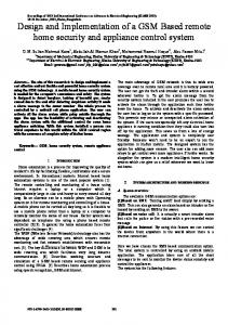
Figure 1. WVM (Wireless Virtual Mesh) Architecture
·
The testbed supports multi-channel and multiinterfaces. This increases mesh network capacity, enhancing the network performance.
·
Mesh module functions independently without modification of the kernel. It provides simple methods for installing and maintaining a mesh module.
A. WVM architecture Firstly, Linux 2.6.21 is used as the base operating system. The proposed Wireless LAN Virtual Mesh Driver (WVM) is located in between the device driver and the Linux TCP/IP stack, as shown in Figure 1. The WVM functions as a master device driver in a manner similar to a bonding driver, which coordinates several device drivers as slave device drivers. Our WVM operates as an independent module without any modifications in the kernel level. All data packets have to pass through the WVM before the packet is passed to the actual device drivers. This means that WVM can support transparency from the upper layer and also independency from the kernel for supporting multiple interfaces. The list below describes the major functions of virtual mesh module and the device drivers. ·
IP/ARP Net-filter: All outgoing packets are conveyed to WVM, but incoming packets are not. To handle incoming packets, we capture them using the Net-filter. Net-filter provides 5 hook handling points for IP packet and 3 hook handling points for ARP packet. WVM sets the hooking point NF_IP_PRE_ROUTING for IP packets, and the NF_ARP_IN for hooking ARP packets. The packets are hooked at these points after arriving at the network layer and finishing the basic processes such as CRC check. As a result, WVN handles the incoming packet without any network layer overhead.
·
Neighbor Management: This component searches a neighbor station and manages link states such as data rate, error rate and allocated channel information. This module also creates beacons for periodic broadcasting.
In this paper, we propose the implementation architecture based on IEEE 802.11s standard and the dual mode mesh AP for flexible bandwidth utilization. III.
SYSTEM ARCHITECTURE
This section describes our mesh testbed architecture and provides details on its essential modules. The list below mentions the major consideration points for implementing our testbed. ·
The testbed is implemented based on IEEE 802.11s standard draft. Especially, the packet handling and network processing are reflected in the system architecture.
·
Channel Management: To utilize multiple-interfaces efficiently, channel allocation must be considered. In the IEEE 802.11s standard draft, the Simple Channel Unification Protocol is proposed.
·
WLAN Mesh Routing: The HWMP based on IEEE 802.11s is implemented in this module. HWMP utilizes MAC address routing which decides multi-hop path using internal routing tables. There are two modes for creating and updating route tables: on-demand mode and proactive tree building mode. The routing table in this module stores the next-hop MAC address and the interface index number according to the multihop destination MAC address.
·
Multi-Interface Forwarding: This component manages slave device interfaces. When the WVM sends the packet to another node, this module delivers the packet to the corresponding slave device.
·
AP Bridge: The Mesh Access Point can support client service via AP bridges. Generally, the 802.11 legacy devices without the WVM module can make a connection to the Internet via AP Bridge function. This component will be explained in detail in the Dual mode Mesh AP.
B. Packet Handling Process Figure 2 shows the process of packet handling. There are two types of packets handled by the WVM module. One is a locally generated packet, and the other is an incoming packet. When WVM receives locally generated packets from the upper layer, it extends the packet header with information such as multi-hop source/destination MAC address. Then it searches its routing table in the WLAN Mesh Routing component and delivers them to the device driver. When incoming packets are received by the Net-Filter, it checks the multi-hop destination MAC address. If the destination is equal to its MAC address, the packet is forwarded to the upper layer. Otherwise the WVM searches the routing table for further packet delivery. When the routing table returns invalid route information, WVM initiates a search for a route path and the packet is stored at the temporary queue until the route information becomes valid. When the searching process is finished, the WVM transmits the queued packet using one of the slave devices. In case of a broadcast packet, WVM delivers the packet to all the slave devices. C. Dual mode Mesh AP This section describes the dual mode mesh access point. As seen on Figure 3, each WLAN driver operates on dual-mode. This means that when the mesh station communicates with other mesh stations, the WLAN device driver functions as the backbone mode. At the same time, that device driver can communicate with the clients without changing modes. To support such a dual mode, the device driver manages the list of clients. When the client associates with the mesh access point, device driver reports to the AP Bridge component for management of routing information. When the mesh access point transmits data to a client, the dual mode device driver
Figure 2. Packet Handling Process
Figure 3. Dual mode Mesh AP Architecture
(a) Packet to client from mesh network
(b) Packet to mesh network from client Figure 4. Proxy Service for Client node
component modifies the frame header such as MAC address filed. The primary reason for the modification is due to the difference of BSSID in mesh network and the infrastructure network. When the data frame is received from the client, the device driver changes the frame header and passes the packet to the Net-Filter. The Net-Filter will in turn pass the packet to the AP Bridge inside the WVM for further treatment. The dual mode mesh AP device driver sets up a same ESSID to other mesh access points. This means that the client can roam to other reachable mesh access point without manual
configuration. When the client associates to a mesh access point, client information is delivered to the AP Bridge component in WVM. Then AP Bridge propagates association client information to other mesh access points to maintain the routing information. The AP Bridge component in the WVM manages the list of the associated clients. When the mesh network finds a route path to client devices that does not have mesh functionality, the AP Bridge component performs a proxy service for the client. Figure 4 shows the proxy service for a client node. When other stations transmit a packet to the client, HWMP generates a PREQ (Path Request) packet to the mesh network. When mesh access points receives a PREQ with the destination as one of the clients, the mesh access point instead replies with the PREP (Path Reply) packet, as shown in figure 4 (a). The opposite case is shown in figure 4 (b). When the client transmits a packet to another mesh station, the client transmits to the mesh access point. The mesh access point performs the route search to find a destination instead of the client performing the search. IV.
IMPLEMENTATION AND EVALUATION
The proposed mesh architecture was evaluated by comparing its performance with the traditional single mode mesh architecture. A. Implementation Environment We deployed nine mesh stations with each mesh system maintaining three interface cards. The traditional single mode architecture selects a mesh interface to support client service while the other interfaces are used for communication between mesh backbones. However, the proposed architecture uses dual mode interfaces to support not only the mesh backbone but also the client service in a single interface. Mesh stations function under the Linux operating system, using kernel version 2.6.21. Each mesh access point is equipped with three WLAN interfaces that use Ra-link WLAN chipset RT2571 [15] with modified dual mode version of Linux device driver. Mesh stations have three interfaces that use Atheros chipset AR5414 [16] with madwifi driver [17]. Each interface on the same machine operates non-overlapping channels. B. Performance Evaluation The preliminary result shows the basic performance of our testbed system. All mesh stations equipped three interfaces and the experiments were accomplished under non-shared and shared channel environments. The non-shared channel used different channels in a path. On the other hand, the shared channel used the same channel in a single path. Figure 5 shows the experimental result of FTP throughput. The 802.11 reference shows the base performance without WVM module with 54Mbps data rate setup. The difference of the base result and the actual data rate is due to the layer processing overhead and interference with other wireless devices in the laboratory. The FTP throughput degradation in shared channel presents the problems of multi-hop wireless network system such as interference. The throughput of non-shared channel maintains high performance even in multi-hop networks. The results
Figure 5. FTP Throughtput
verify that the multi-channel multi-interface environment can prevent the decreasing network performance The result shows the maximum capacity of mesh backbone and client service. Single mode mesh access point has two backbone interfaces and one AP service interface, while dual mode mesh access point operate both. Firstly we configured the CMAX (mesh station maximum capacity) value which is the sum of the maximum value of each CI (single interface capacity). Three types of traffic are defined: TB (Background traffic) is the data traffic that is forwarded from the neighbor mesh station to another mesh station. TO (Outgoing traffic) is the data traffic that is generated by the mesh access point and also the packets destined from the client to another mesh station. TC (Client traffic) is the traffic between AP and the client for supporting client services. Generally, TO is assumed to be greater than TC, because TO includes forwarding data packets from the client and also the data packets generated by the mesh station itself. We can write this equation as shown below:
TO ³ TC
(1)
CMAX depends on N (number of interfaces) and the sum of TB, TO, and TC cannot exceed CMAX. We formulate the equation (2) and (3) using this definition: N
C MAX = å C I
(2)
C MAX ³ TB + TO + TC
(3)
i =1
When we set the TB value to 0 and increment it, we can derive the maximum TC value. When we set the TC value from 0 to CI, we can also get the maximum TB value. NC is number of interface for AP service and NB is number of mesh backbone interface. Maximum value of TC is less than TO, so we can acquire the equation (4), (5):
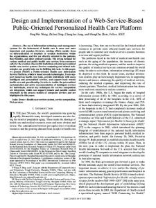
(a) Maximum capacity of Client Service
(b) Maximum Capacity of Backbone Figure 6. Maximun Capacity
Max (TC ) = Min{(C MAX - TB ) / 2, N C C I }
(4)
Max (TB ) = Min{C MAX - 2TC , N BC I }
(5)
Figure 6 shows the theoretical results (T) and experimental results (E) of the test-bed. The maximum client service capacity has been estimated in relation to the background traffic. In the single mode, each interface operates exclusively as a backbone or a client service. This means that single mode mesh stations have low flexibility for distributing capacity for both the mesh backbone and the client service. When there are low background traffic, mesh stations that use dual mode can enhance the capacity of client service and flexibility. On the other hand, single mode mesh stations waste the capacity even though there is extra capacity remaining on the backbone interface. Figure 6 (a) represents maximum capacity of client service. As the background traffic increases, the rate of client service degradation becomes more obvious. When the background traffic exceeds 100% of CI, TO cannot be fully utilized due to the limitation of the backbone capacity. This means that the capacity that needs to be used for client service is instead used for supporting background traffic, which leads to decrease in client capacity. In the proposed dual mode, the capacity other than the area used for the backbone traffic is used for supporting TC and TO. Therefore, the dual mode shows less decrease in the performance than its counterpart. The difference between theoretical results and experimental results is due to interference and additional packet processing overhead. Figure 6 (b) appears maximum capacity of mesh backbone. As the client service traffic increase 50% of CI from 0, the capacity of TB in single mode is limited. The dual mode can provide client service to exceed 100% of CI using all the interfaces. V.
CONCLUSION
In this paper we proposed the WVM architecture and implemented the testbed based on IEEE 802.11s using dual mode device driver. We evaluated the performance of the client
service. The results show that the dual mode system enhances the client service performance and flexibility compared with single mode system. Future work includes implementing load balancing schemes for supporting QoS between backbone and client service REFERENCES [1]
[2]
[3]
[4]
[5]
[6]
[7]
[8]
[9] [10] [11] [12] [13] [14] [15] [16] [17]
I. Akyildiz, X. Wang, and W. Wang, “Wireless Mesh Networks: A Survey”, Elsevier Computer Networks, vol. 47, no. 4, pp. 445-487, March, 2005. Piyush Gupta, P. R. Kumar, “The capacity of wireless networks,” In IEEE Transactions of Information Theory, vol. 46, no. 2, pp. 388-404, March, 2000. John Bicket, Daniel Aguayo, Sanjit Biswas, and Robert Morris, Architecture and Evaluation of an Unplanned 802.11b Mesh Network , In ACM Mobicom 2005, August 2005. Jungmin So and Nitin H. Vaidya, “Multi-Channel MAC for Ad Hoc Networks: Handling Multi-Channel Hidden Terminals Using A Single Transceiver,” In ACM Mobihoc 2004, May, 2004. Chandrakanth Chereddi, Pradeep Kyasanur, and Nitin H. Vaidya, “Design and Implementation of a Multi-Channel Multi-Interface Network,” In REALMAN 2006, May 2006 Ashish Raniwala, Tzi-cker Chiueh, “Architecture and Algorithms for an IEEE 802.11-based Multi-channel Wireless Mesh Network,” In IEEE Infocom 2005, March, 2005. Saumitra M. Das, Himabindu Pucha and Y. Charlie Hu, “Mitigating the gateway bottleneck via transparent cooperative caching in wireless mesh networks,” In Elsevier Ad Hoc Networks, vol. 5, issue 6, pp. 680-703, August, 2007. Myung-J. Lee, Jianliang Zheng, Young-Bae Ko and Deepesh Man Shrestha, “Emerging Standards For Wireless Mesh Technology,” In IEEE Wireless Communications, Vol. 13, Issue 2, pp. 56-63, April, 2006 IEEE P802.11sTM/D3.02 “Amendment: Mesh Networking,” May, 2009. MIT roofnet Project, http://pods.csail.mit.edu/roofnet/ Net-X Project, http://www.crhc.uiuc.edu/wireless/netx.html/ Mesh Dynamics, http://www.meshdynamics.com/ Motorola Mesh Networks, http://www.motorola.com/ NOTEL Wireless Mesh Setwork Solution, http://www.nortel.com/ Ralink Technology, http://www.ralinktech.com/ Atheros, http://www.atheros.com/ MadWifi Project, http://madwifi-project.org/