2014 International Conference on Signal Processing and Integrated Networks (SPIN)
Design and Implementation of an MSI number based Image Watermarking Architecture in Transform Domain Koushik Mahanta Electronics and Communication Assam Don Bosco University Guwahati,India
[email protected]
Dibya Jyoti Das Electronics and Communication Assam Don Bosco University Guwahati,India
[email protected] Ankita Dutta Electronics and Communication Assam Don Bosco University Guwahati,India
[email protected]
H.M.Khalid Raihan Bhuyan Electronics and Communication Assam Don Bosco University Guwahati,India
[email protected]
Mriganka Gogoi* Electronics and Communication Assam Don Bosco University Guwahati,India
[email protected] Abstract— Hardware based digital image watermarking is in
I. INTRODUCTION
a good demand these days because of its fast real time implementation. It is seen that hardware based watermarking often comes with computational complexity and difficulty in implementation. In this paper, we discuss the development and implementation of the hardware architecture of Digital Image Watermarking in transform domain using a newly developed simple yet secured algorithm. Walsh Transform is used to convert the cover image from spatial domain to transform domain as it is a secured Transform function and it is also feasible to synthesize the developed architecture using HDL (Hardware Description Language) synthesizer. The proposed architecture is not very resource rich. The proposed watermarking architecture will be very useful particularly for image authentication process and secured transmission of message inside an image. Here, the proposed algorithm embeds the watermark into a cover image and also extracts it at the receiving end using the MSI numbers generated during the watermark insertion process. One significant advantage of the algorithm is that there is no need of the original image to extract the watermark at the receiving end. The whole work can be viewed as the sequential amalgamation of three subtasks: theoretical modeling, designing the hardware architecture in Verilog HDL and performance observation by an adopted simulation set-up. The complete designed architecture is found to be compatible for verification using Field Programmable Gate Array (FPGA) for VLSI implementation.
This is the time when most of the data and information around us are digitized. Text, image, audio and video-- all are developed, stored, maintained and shared in digital form. Consequently, problems started arising regarding the safety and security of the digital information since it became easily accessible to anyone. Possibility in creating multiple copies of any digital data is causing a threat to ownership, authenticity and identity of digital data. The Digital Watermarking is a technique which is mainly used for authentication, copyright protection, source tracking and broadcast monitoring. In digital watermarking, any digital information is embedded into another information/data without causing permanent damage to the carrier data and message data, keeping the information protected in its original form. The digital image watermarking process can be done in both the Spatial Domain and Transform Domain. In this proposed work, watermarking is performed in transform domain ,where the cover image is converted from Spatial Domain to Transform Domain using transforms like DCT(Discrete Cosine Transform), WT(Walsh Transform), DWT(Discrete Wavelet Transform) etc. and then the watermark is inserted and embedded with the transformed values according to the algorithm in a robust manner. In the proposed work, Walsh transform is used to establish the transform domain. Since Walsh Transform deals with Walsh Codes, it brings security and robustness to the watermarking process. This Walsh transform based design work causes low computational cost and it’s fast and easy to implement in hardware thus making it suitable for real time application. The proposed architecture cause very small information
Keywords— VLSI, FPGA, HDL, MSI, Digital Image Watermarking.
978-1-4799-2866-8/14/$31.00 ©2014 IEEE
157
2014 International Conference on Signal Processing and Integrated Networks (SPIN)
change during watermarking process due to the efficient application of the algorithm with the Walsh transform module.
and his team. They proposed a novel combined multipolarity arithmetic–Walsh transform, in which recursive relationships between higher and lower matrix orders of hybrid multi-polarity arithmetic–Walsh transform are developed [11]. Kishan Chand Gupta and Palash Sarkar studied the relationship between the Walsh transform and the algebraic normal form (ANF) of a Boolean function. Their algorithm can be applied in situations where it is practically impossible to use the fast Walsh transform algorithm [12]. Patrick Gaydecki and his colleagues proposed a technique in which it inserts bits of binary hand written signatures in the DCT blocks of a digital image. In the proposed method, the 1-D Walsh functions are used to encode the signature before being embedded in the cover image[13].
II. RELATED WORK In recent times, many researchers have worked on digital watermarking focusing on different facets of this field. The earliest Spatial domain techniques were perhaps implemented at MIT. W. Bender D and his team embedded data into digital media mainly aiming these three applications: copyright protection, tamper-proofing, and augmentation data embedding [3]. Digimarc corporation developed a digital watermarking technique featuring a unique owner ID which was considered as the foundation for protecting digital images to communicate ownership and usage rights via the Digimarc website [5].One of the first and perhaps still the most cited frequency domain technique was proposed by Cox et. al.[6] They presented a secure (tamper-resistant) algorithm for watermarking images, and a methodology for digital watermarking that may be generalized to audio, video and multimedia data. They advocated that a watermark should be constructed as an independent and identically distributed Gaussian random vector that is imperceptibly inserted in a spread-spectrumlike fashion into the perceptually most significant spectral components of the data. Hesham A. El Zouka introduced a new approach that enables the designer to conceal the very existence of the message: a key which is based on a seed number will be communicated and generates a sequence of numbers that identifies bits in the host digital media file that contains the secret message [2].Rajesh Kannan Megalingam and his colleagues presented a comparison with the conventional watermarking technique and the novel 5-stage pipelined implementation of DCT/IDCT which is used in digital image watermarking[4]. Yong-Jae Jeong proposed a real-time video watermarking chip and system which is hardware based watermark embedding system of HD (high definition) video with STRATIX FPGA device from ALTERA [7]. Abhishek Basu and his team tried to develop a low power, real time, reliable and secure data hiding system that can be achieved all the way through hardware implementation. As an attempt towards the power efficient system, they presented an oblivious, spatial domain watermarking based authentication algorithm [8]. Amit M Joshi combined the advantages of Wavelet based frequency domain watermarking (for robustness) with bit plane slicing scheme (for less computational complexity) in his proposed algorithm[9].Ravi Shah put forward a real time implementation of an algorithm for Watermarking and the results obtained using a Frequency domain approach. Their work emphasized an Adaptive Frequency domain watermarking approach in real time, demonstrating robustness against intentional or unintentional attacks on the watermarked image. This was achieved by modifying the middle frequency coefficients[10]. A transform domain watermarking implementation was carried out by S. Yan
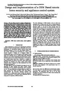
III .PROPOSED WORKING MODEL The ultimate purpose of the work is to offer a watermarking system which can be implemented in hardware with robustness, security and significantly less data loss to make it suitable for fast real time application. The proposed work will be very much useful in sending binary image containing texts as watermark along with the cover image. The transmitter and receiver block contains several components which are used at various stages of the flow of computing and are shown in the following block diagrams: A. Transmitter Block:
Fig. 1. Block Diagram of Transmitter
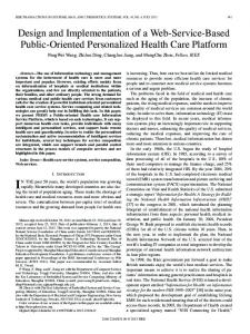
B. Receiver Block:
Fig. 2. Block Diagram of Receiver
158
2014 International Conference on Signal Processing and Integrated Networks (SPIN)
IV. THEORETICAL DETAILS OF THE TRANSFORM FUNCTION
A 4×4 binary image is taken as the watermark image. WI(i) is the watermark pixel where i takes values as 1,2,3,……….to 16. WI(i) is treated with a random pseudo noise sequence and accordingly the position of WI(i) is changed from initial value i.e. it’s a kind of random position swapping between randomly choosen pair of pixels. After position change we will get new pixels WIP(i).
A. Theoretical Details of Walsh Transform We have decided to use 1D Walsh Transform as the Transform function to convert the cover image from Spatial Domain to Transform Domain. The kernel of the Walsh Transform can be given as:
Step 3: MSI number generation & watermark embedding. MSI numbers means Message State Indication numbers. In the MSI number generation unit, these numbers are generated by analysing the bit pattern of the randomly selected values of transformed cover image pixels. Firstly, from all the transformed cover image pixels, 16 pixels are randomly selected according to a PN sequence. Then, the 5th bit or 6th bit or 7th bit is to be selected, of course randomly, from the bit pattern of that particular selected pixel. Let the selected bit is Ri(m) where m can take values 5,6 or 7 as mentioned and i takes values as 1,2,3…….to 16 Now, the bit pattern of all the position changed pixels i.e. WIP(i) of the message image are evaluated and for each bit pattern for each pixel,a track bit t(i) is generated corresponding to the result of the bitwise AND operation of the bit pattern. Here, i varies as 1,2,3…..to 16. Now, for i =1 to 16 if t(i) = = Ri(m) msi(i) = 0; else msi(i) =1;
where N= No. of input pixels from an image and n is such that N=2n . bi(x) means ith bit of the binary representation of x. Similar is the case with bn-1-i (u). Finally, we get the transformed values after multiplying the kernel with the input pixel values as follows:
where f(x) is the input image pixel. B. Theoretical Details of Inverse Walsh Transform The inverse kernel of the Fast Walsh Transform is same as the forward kernel of Fast Walsh Transform i.e.
and the final inversed values can be found as: IW(u)=f (x)×N×g(x,u)
(4)
So, finally we will get the inverse Fast Walsh Transform as :
Where f
Thus, a 16 element array ‘msi’ is obtained which contains 16 MSI code bits. And these are stored in two 16-bit registers each contains 8 of those numbers. These are stored in the part starting from 9th bit position to 16th bit position. In this way, MSI numbers are made ready to be transmitted. During the process, the bit in all the selected bit position of the randomly selected transformed cover image pixels, is compared with each track bit and the result is tracked according to the message pattern. This process is repeated for all message image pixels. And finally watermarked inserted approximated pixels ChWP(i) are found.
(x)=W (u);
V. PROPOSED WATERMARKING ALGORITHM . A. Watermark encoding: Step 1: Perform Walsh transform on the cover image
Step 4: Perform Inverse Walsh Transform
Walsh transform (as shown in the para) is performed on the cover image. The sample taken in our work as cover image is an 8×8 block containing 64 pixels. Each pixel C(i) is transformed and the transformed pixels CW(i) are obtained which are some real values containing fractional parts and values can be positive or negative. Walsh transform kernel deals with the walsh codes generated during the process.
Now, the watermark inserted image is allowed to undergo Inverse Walsh transform i.e. pixel ChWP(i) is Inversely Walsh Transformed to get pixel ChP(i). Step 5: Transmit the watermark inserted image along with the MSI numbers The algorithm is designed to transmit the watermarked image and MSI numbers in serial mode although it can be modified to deliver parallel transmission.
Step 2: Change the pixel positions of the watermark/message image by using a random pseudo noise sequence.
159
2014 International Conference on Signal Processing and Integrated Networks (SPIN)
B. Watermark decoding: Step 1: Perform Walsh Transform on the received image. The first step at the receiving end is to again perform Walsh transform on the received watermarked image. Each pixel Ch(i) of the received watermarked image will be transformed to ChW(i).
Here, f(x) is the one dimensional (1D) image function which gives integer values ranging from 0 to 255 for grey scale image. So, change in the magnitude of f(x) can affect the transformed values W(u). Let f(x) = m and the changed f(x) i.e. f (x) = m1 then data change (¨m) is |¨m|=|m-m1| where 0|¨m|255. So change in transformed values i.e.
Step 2: Watermark extraction with the help of MSI numbers. Now, the approximated transformed pixels ChWP(i) are treated with MSI numbers msi(i) to get the message. Again, from all ChWP(i), 16 pixels are randomly selected according to the same PN sequence used in the transmitter. Now, for i=1 to 16 if msi(i)= = 0 t(i)=Ri(m); else t(i)= ~ Ri(m); where t(i) & Ri(m) are the two same entities generated in the transmitter. ~Ri(m) is the complement of Ri(m). Now, each track bit t(i) is expanded using the reverse of the AND evaluation used in the transmitter to get the message pixels in WIP(i) form.
¨W(u)=¨m×W(u)
(8)
Significantly a change in W (u) i.e. ¨W(u) is only possible if there is ¨m and this can happen only when there is change in the image pixel values.
Where, f Now,
Step 3: Inversely change the pixel positions of the decoded message to get the message in its original form.
(x)=W(u) IW(u)= ¨m× IW(u)
(10)
As after the watermarking process, Inverse Walsh transform is to be performed, the change ¨m will also be inversed back. So in this process, if data change occurs before the Walsh transform then that change will propagate to the Inverse Walsh transform. By no way that data change can occur at an isolated part of the transmitter architecture. Since, the data change will propagate throughout the embedding process, then also watermark insertion can be performed. The algorithm will extract the message considering that data change at both the Walsh transform and Inverse Walsh transform module keeping the track or pattern of the particular bits of the involved pixels.
Now, WIP(i) are treated with the same PN sequence to get the pixels in their actual position as WI(i). All the pixels WI(i) are now representing the original binary message image. Thus, we retrieved the original message image at the receiving end. VI. PERFORMANCE STUDY In the proposed watermarking scheme, the MSI (Message State Indication) numbers are generated during the watermark embedding process. These MSI numbers work as a kind of dynamic protection to the hidden message against any attacks. In this design, MSI numbers are stored & sent with the watermarked image in two 16 bit registers like the image pixels. In the implemented design, during storage and transmission, the binary MSI bits are embedded into higher bit planes. So, small and medium change in magnitude of the MSI registers will not change the binary MSI bits. Moreover, while extracting the watermark, MSI numbers work in a sequence which was followed during the watermark embedding process. During the watermark extracting process, the MSI numbers try to find the track bits by comparing multiple combinations of the higher order bits of some particular pixels of the transformed and approximated watermarked image and in this way security is maintained.
B. Change in information due to MSI number loss: MSI numbers are the key elements in safeguarding and retrieving the watermark message. If the MSI numbers are tampered or lost, the message may not be retrieved correctly. There are 16 MSI numbers for a 4×4 watermark binary image : msi(1),msi(2),………….msi(16) etc. A minimum loss or change in case of one msi(i) can change the watermark message. The watermarked pixels and the MSI numbers should be transmitted according to the sequence to prevent distortion of the original message image.
A. Change in information due to Walsh transform:
160
2014 International Conference on Signal Processing and Integrated Networks (SPIN)
VII. VLSI DESIGN
output ports of the Watermark Insertion module. The generated 16 MSI numbers are stored in two 16 bit registers msiX[15:0] and msiY[15:0]. e) Watermark Extraction module: In this module, the MSI numbers and the output of the Walsh Transform module (for received image) are given as input to extract the hidden message. The received MSI numbers from msiX[15:0] and msiY[15:0] are applied along with output of the Walsh Transform module in the receiver i.e. covimg1[15:0], covimg2[15:0],……………….covimg64[15:0] to extract the original message.
The complete watermarking architecture was coded in Verilog HDL using Xilinx ISE. It is coded for easy testing with the help of Xilinx Spartan FPGA. All modules are synthesized independently and assembled together to form the complete hardware architecture: a) Walsh Transform module. b) Inverse Walsh Transform module, (c) Watermark Insertion module, (d) MSI Number Generation module, (e) Watermark Extraction module, (f) Pass-code Protection module (optional) , (g) Assembled Transmitter module, (h) Assembled Receiver module.
f) Pass-code Protection module (Optional): This module is designed to accept 16 bit long pass-code. The already set pass-code is stored in internal register. The user-entered pass-code is again stored temporarily in registers and then compared. If correct pass-code is entered, received data will be able to go to the decoding section otherwise all received pixels will be masked not allowing the decoding process. It is an optional module designed to provide additional dynamic protection.
a) Walsh Transform module: We designed the Walsh Transform module for 64 element to take 64 pixel (8x8) image as the coverimage as the input to the Walsh Transform module. This module is designed to accept input pixel values in parallel mode. ipix1 [15:0], ipix2[15:0], ipix3[15:0], ipix4[15:0],…………………………..ipix64[15:0] are the16 bit input ports to take the 64 input pixels. The clock signal ‘clk’ (1 bit) and reset signal ‘rst’ (1 bit) are used to control this sequential block designed in behavioural style. Intermediate values during the calculation, are stored in registers.Finally,opix1[15:0],opix2[15:0],opix3[15:0],opix4[ 15:0],…………………..,opix64[15:0] are the 16 bit output ports to give the transformed pixel values. b) Inverse Walsh Transform module: This module was designed to accommodate all the 64 transformed watermarked pixels and to recover the Spatial Domain values. The input and output ports of this module are same as those of the Walsh Transform module. It only differs in terms of the computation formula as shown in the theoretical details of the Inverse Walsh Transform.
g) Assembled Transmitter module:The transmitter module consists of the Walsh Transform module, Inverse Walsh Transform module, Watermark Insertion module and MSI Number Generation module. Here, all the individual blocks are designed in behavioural modelling and finally, all the modules are instantiated as sub-modules in the main transmitter module. It’s a mixed modelling. h) Assembled Receiver module:The receiver module has two sub-modules—the Watermark Extraction module and Walsh Transform module. This Receiver module is also designed in mixed modeling style. A. Results of the VLSI design
c) Watermark Insertion module: In this module, the watermark image pixels and the outputs of the Walsh Transform module are given as input to perform the watermark embedding process. It also triggers the MSI Number Generation process. Here, the inputs are watermark image pixels and the transformed pixel values-opix1[15:0], opix2[15:0],…………,opix64[15:0] which are obtained from the output ports of the Walsh Transform module. It generates watermark inserted pixel values. d) MSI Number Generation module: In this module, there are two registers to store 16 MSI numbers. These MSI numbers are generated by comparing particular cover image pixel values with watermark image at several levels of extraction according to the algorithm as discussed in the watermarking algorithm part. This module is designed using more digital logic and less mathematics. AND gate and XOR gate logics were exclusively used in this module. Here, the inputs are watermark image pixels and transformed watermarked pixels. WI1[15:0], WI2[15:0],…………………….WI16[15:0] are the 16 bit input ports to accommodate the watermark image pixels and the transformed watermarked pixels are available from the
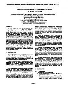
Since the focus is on the implementation of the architecture on the hardware, therefore coding for the whole watermarking process was done in Verilog HDL and it was synthesized using Xilinx ISE, instead of going for the diagrammatic presentation of the architecture.
Fig. 3. Main RTL of the main Transmitter block and Zoomed in view of the Transmitter block.
161
Fig. 4. main RTL block of the Receiver and internally generated RTL structure of the Receiver module. Fig. 7. Simulink®-ModelSim® model for the Transmitter part.
The whole hardware architecture design is coded in Verilog HDL using the synthesizer Xilinx® ISE 8.2i and for testing purpose ModelSim® simulator was linked with the Simulink® of Matlab® 7.8. B. Working of the Performance evaluation set-up and the Results: The testing of the Walsh transform module for 64 pixels is performed using ModelSim® and Simulink® interface as shown in figure 8.
Fig. 8. image.
The input pixels (inWI1 to inWI16) of the binary watermark
The screenshot of the generated MSI number is shown in Figure 9.
Fig. 9. The generated MSI numbers.
Fig. 5. Some approximated transformed pixel values in Modelsim® for 64 element Walsh Transform.
In Figure 9, the msiX and msiY are the two internal registers where the MSI number values are stored temporarily and then the MSI number values are transferred to the output ports txOUT1 and txOUT2 for transmission to the receiver.
C. Results of the Watermark insertion and extraction algorithm: In the transmitter part, the watermark has been embedded into the cover image. The watermark which was embedded is shown in Figure 6.
The screenshot displaying some of the pixel values (txO1 to txO27) out of all the 64 pixels of the human readable image is shown in Figure10.
Fig.6.Added binary watermark image
The whole transmitter part can be shown in the Simulink® model window and is shown in Figure 7. Fig. 10. Some of the pixel values (txO1 to txo27) of the human readable image.
162
Implementation of Robust Watermarking System,Fifth International Conference on Information Technology: New Generations, Pages 1-5 [3] W. Bender D. Gruhl N. Morimoto and A. Lu. Techniques for data hiding, IBM Systems Journal, 35 (3-4),Pages 313–336, 1996. [4] Rajesh Kannan Megalingam, Venkat Krishnan B., Vineeth Sarma V., Mithun M., Rahul rikumar, Department of Electronics and Communication, Amrita School of Engineering, Amrita Vishwa Vidyapeetham, Kollam, Kerala, India, Hardware Implementation of Low Power,High Speed DCT/IDCT Based Digital Image Watermarking, International Conference on Computer Technology and Development, 2009, Pages 1-5
Fig. 11. Screenshot displaying the pixel values of the retrieved binary watermark image.
[5] Digimarc Corporation:http://www.digimarc.com/digimarc-for-images.
It is seen that the pixel values of the binary watermark image which was embedded in the transmitter is same as the pixel values of the retrieved binary watermark image at the receiver.
[6] Ingemar J. Cox, Joe Kilian, Tom Leighton and Talal Shamoon, Secure Spread Spectrum Watermarking for Multimedia, IEEE Trans. on Image Processing, 6, 12, 1673-1687, (1997). Copyright IEEE, Page 1-31 [7] Yong-Jae Jeong, Won-Hee Kim, Kwang-Seok Moon, and Jong-Nam Kim Pukyong National University, Nam-Gu Pusan City Korea, FPGA Based Implementation of Real-Time Watermarking for High Definition Video, International Symposium on Intelligent Signal Processing and Communication Systems (ISPACS 2009) December 7-9, 2009, Page 14
To get the visual representation of the retrieved watermark in the receiver, the set up of the Simulink® model window is established as shown in Figure 11.
[8] Abhishek Basu, Tirtha Sankar Das, Somnath Maiti, Nurul Islam and Subir Kumar Sarkar, FPGA Based Implementation of Robust Spatial Domain Image Watermarking Algorithm, International Conference on Computers and Devices for Communication,2009, Page 1-4 [9] Amit M Joshi, Anand Darji and Vivekanand Mishra, Electronics Department, SVNIT, Surat, India, Design and Implementation of RealTime Image Watermarking, Page 1-5
Fig. 12. Retrieved binary watermark image.
[10] Ravi Shah, Abhinav Agarwal and Subramaniam Ganesan, Department of Computer Science and Engineering, Oakland University, MI-48309, Frequency Domain Real Time Digital Image Watermarking, Page 1-6
VIII. CONCLUSION & FUTURE WORK Based on the experience throughout the development of this algorithm, it is observed that the design of the Hardware Architecture of Digital Image Watermarking in transform domain is a complex process as it involves various problems related to synthesis of the hardware architecture with optimum precision, related to compatibility issues among various hardware components and platforms etc. It is difficult to design the hardware architecture of Digital Image Watermarking with very high precision when the algorithm involves more theoretical computational complexity. The designed watermarking system can take only on gray scale cover image and binary watermark image, watermark cannot be recovered if the MSI number is destroyed. Also this algorithm can be upgraded to support multi transform functions. IX.
[11] B.J. Falkowski and S. Yan, Hybrid multi-polarity arithmetic–Walsh transform, IEEE Proc.- Circuits Devices Syst., Vol. 153, No. 6, December 2006, Pages 1-8 [12] Kishan Chand Gupta and Palash Sarkar, Computing Partial Walsh Transform From the Algebraic Normal Form of a Boolean Function, IEEE Transactions on Information Theory, Vol. 55, No. 3, March 2009, Pages 16 [13] Patrick Gaydecki, Kamal A. Ahmed and Hussain Al Ahmad, A Blind Block Based DCT Watermarking Technique for Gray Level Images Using One Dimensional Walsh Coding, Pages 1-5
REFERENCES
[1] R. Chandramouli,Department of ECE, Stevens Institute of Technology Hoboken NJ, 07030, Nasir Memon, Department of Computer Science, Polytechnic University, Brooklyn, NY 11201 and Majid Rabbani, Imaging Research & Advanced Development, Eastman Kodak Company,Rochester, NY 14650 Digital Watermarking, Pages 1-21 [2] Hesham A. El Zouka, Computer Engineering Department, Arab Academy for Science and Technology, Alexandria – Egypt, FPGA Based
163