[9] Yu-Yau Guo, Jien-Chung Lo, and Metra C., âFast and area- time efficient Berger code checkers,â Proc. 1997 IEEE Int. Symp. on DFT in VLSI Systems, pp.
On the Design of Self-Testing Checkers for Modified Berger Codes Stanislaw J. Piestrak Wroclaw University of Technology Institute of Engineering Cybernetics 50-370 Wroclaw, Poland piestrak @ ict.pwr.wroc.pl
Dimitris Bakalis & Xrysovalantis Kavousianos University of Patras & Computer Technology Inst. Dept. of Computer Eng. & Informatics 26500 Patras, Greece {bakalis,kabousia} @cti.gr
Abstract
implement SC circuits are Berger codes, which are the optimal systematic unordered codes capable of detecting unidirectional errors of any multiplicity. The reliable operation of a checker could be ensured by implementing it as a selftesting checker (STC) which is capable of detecting its own internal faults during normal functioning. Although several STCs for Berger and equivalent codes have been proposed in the past [2]-[10], they mostly present area and delay results based on gate counts and gate levels and not on real implementations. Actually, the only work that addressed the design of low-power consumption in SC circuits deals with 2-rail STCs only [ 1 I]. In this work we consider real implementations and present and evaluate the area, delay and power characteristics of STCs for modified Berger codes that are based on: (a) parallel counters and (b) sorting networks.
One of several approachesf o r designing highly-reliable systems relies on using error detecting codes (EDCs) and implementing digital circuits as selj-checking. One class of EDCs that has been very often used to implement selfchecking circuits are Berger codes. Although several selftesting checkers (STCs)f o r Berger codes have been proposed in the past, they mostly present area and delay results based on gate counts and gate levels and not on real implementations. In this work we consider real implementations and present and evaluate the area, delay and power characteristics of STCs for mod$ied Berger codes that are based on: (a)parallel counters and (bj sorting networks. Preliminary results indicate that STCs based on parallel counters are smaller and consume less power than the STCs based on sorting networks.
2 Preliminaries
1 Introduction
2.1 Power Dissipation in CMOS VLSI Circuits
This project is motivated by the growing needs to provide aerospace and life support systems (such as pacemakers) demanding both high-safety and low-power performance. In 1997 it has been reported that not only charged particles from the Sun but also neutrons have sufficient energy to flip bits in memories and corrupt logic inside processors [l]. The major concern is logic, which, unlike memory cannot be easily protected using parity checking or Hamming error correcting codes. The implementation of radiation hardened circuits is not always feasible or cost-efficient. The US Federal Aviation Administration confirmed that one in 10 avionic failures are unconfirmed on the ground, i.e. they might have been transient faults caused by cosmic radiation (called single event upsets (SEUs)). One of several approaches for designing highly-reliable and/or safe systems relies on using error detecting codes (EDC’s) and implementing digital circuits as self-checking (SC). One class of EDC’s that has been very often used to
0-7695-1290-9/01 $10.00 0 2001 IEEE
Two types of power dissipation in CMOS circuits are distinguished [ 121: dynamic and static. Dynamic power dissipation is caused by switching activities of the circuits. Static power dissipation is related to the logical states of the circuits which, in CMOS logic, is caused by the leakage current only and it is generally negligible. The most significant source of dynamic power dissipation in CMOS circuits is the charging and discharging of capacitance. It strongly depends on the activity of the inputs and outputs of logic gates. Only the latter component of power dissipation will be taken into account here.
2.2 STCs and Berger Codes Definition 1 1131, [I41 A circuit is called a self-testing checker (STC) i f i t is both:
153
f from the set F of likely faults i f produces a non-code output word f o r at least one input codeword; and
1. Self-testing (ST), i.e. f o r every fault
0
The latter circuit might have an arbitrary structure, since all 2 K combinations are used as check parts. One of the most efficient highly modular implementations is a tree of 2-pair 2-rail modules such as shown in Figure 7. A counter of 1's can be built using two essentially different complementary concepts [7]:
2. Code-disjoint (CD), i.e. it maps the input code space
to the output code space and the input non-code space to the output non-code space.
Definition 2 (1.51 The Berger code C ( I , K is ) a systematic code wherein the K check bits Pdy = { s K - I , . . . , S I , so} are the binary representation of the bit-by-bit complemented number of 1 s in the information part JX = { X I ,x 2 , . . . , X I } , where K = r10g2(I 1)1.
1. as a parallel counter (PC)-a circuit built on the basis of carry-save adders (CSAs) entirely composed of fulladders (FAs) and half-adders (HAS); and
+
2. using a multi-output threshold circuit T' followed by some NOT-AND-OR circuit.
Definition 3 1.21 A Maximal Length Berger (MLB) code C M L B ( Kis) one f o r which K = log,(I + 1), i.e. I = 2 K - 1.
The most hardware-efficient versions of the latter circuit, that will be referred to a TI-based counter of I 's, can be designed by implementing T I as a sorting network (SN) [6], [ 171. Several realization of SNs can be found in [ 181-[20]. Despite being the least complex, the SNs have also been shown easily-testable, since a circuit T" implemented as a SN can be tested for all single stuck-at-z ( s / z )faults, z E (0, 1},using from 3n/2 to 2n tests only [17], [21]. The gate count indicated that the SN-based STCs are superior than their PC-based counterparts for smaller I [7], [8]. Nevertheless, no realistic comparison of area, delay and power dissipation of these circuits has ever been reported.
One advantage of a MLB code is that all 2 K check parts are used, what facilitates the implementation of an STC. However, the most important class of the Berger codes are combinational ). those with I = 2K-1, i.e. C ( 2 ~ - ~A, ~ STC for Berger codes with I = ZK-' could not have been built until very recently [16]. At the time (1977), this limitation motivated the construction of a class of equivalent modified Berger codes for which a combinational STC could be built [2]. For I = 2K-1 these codes are constructed as the concatenation of the MLB code with the 1-out-of-2 (1/2) code Cy2K-1,K) = C ( 2 K - 1 - 1 , K - 1 ) c1/2, (1)
3
where C ( 2 ~ - 1 - 1 , ~ -is- 1the ) MLB code and two bits of a 112 codeword represent X I - the most significant bit (MSB) of the information part, and S K - ~- the MSB of the check part, i.e. S K - ~= G. Modified Berger
1-out-of-2
Code
Code
an STC for the K-pair 2-rail code.
Design of STCs for Modified Berger Codes with I = 2K-1
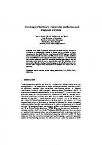
We have shown in [22] that the 2-output combinational checker for Berger codes with I = 2K-1 information bits proposed by Rao et al. [23] is not self-testing, as claimed. Essentially, such a checker can be built using a special STC for 2-rail codes, proposed recently in [ 161. However, here we will consider a slightly simpler and faster STC for the modified Berger codes from [2], according to Fig. 1.
3.1 Design of Basic Blocks Figure 1. General structure of an STC for the modified Berger code C;K-l,Kfrom [6].
Here we shall consider implementations of the STCs for the following modified Berger codes: C;8,4),C;16,5),
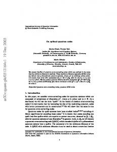
and '?64,7)' The PC-based checkers employ the 7-, 15-, 31-, and 63input PCs respectively built of 4, 11, 26, and 57 FAs. The SN-based checkers employ the circuits T7, T1', T31,and T63designed as follows. The circuit T7 is the optimal SN by Batcher [18]. The circuit T15 is obtained by removing the bottom line along with all connected comparators in the optimal 16-input SN from [19] (see Fig. 2). The circuit T31 is built using the circuits T15 and T16(either built according ';32,6)*
Consequently, an STC for the modified Berger code
C;2K-,,K)can be built as shown in Fig. 1 [6]. It consists of only two blocks: 0
an encoder for the MLB code C ( ~ K - I - ~ , K with -~) complemented outputs, which is nothing else but the (2K-1 - 1)-input counter of 1's; and 154
to [19]) followed by the 16-by-15 odd-even merging network (MN) designed according to Batcher [18]. A similar approach is used to build the circuit T3*.The latter is a part of the circuit T63, which consists of the circuits T 3 2and T31followed by the 32-by-31 odd-even MN. Either version of a checker employs an identical 4-, 5-, 6- or 7-pair TSC comparator built using 2-pair 2-rail modules (see Fig. 7).
0
two outputs {SI, so}, which are complement of each other, when there are no input errors or internal faults.
Figure4. Truth table and logic functions of the 15-input counter of 1's with complemented outputs, built using T15. Figure 2. Optimal 16-input SN from [19].
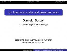
The principal part of the T15-based STC for the modified Berger code C;ls,5)designed according to [6] (see Fig. 3) is the T15-based counter of 1's. It implements the functions derived with the help of the truth table, both shown in Fig. 4. It is a circuit composed of the 15-input SN (see Fig. 2) with 15-inputs { z 1 , z 2 ,... , z 1 5 }and 15 outputs {TI15 ,~ 1 , .5. . ,Tf:} followed by some NOT-AND-OR cir-
3.2 Example: STCs for the Modified Berger Code with I = 16 To present the basic design ideas, we show the detailed structures of two versions of an STC for the modified Berger code CT16,51 in Figures 3 and 5 . The logic schemes of all subcircuits needed to build these two realizations are shown in Figures 2-7. I
z},
cuit with four outputs {G,5,F, which are the regenerated complemented check bits. These are then compared against the set of original check bits {s3, s2, SI,so) along with a pair of bits s 4 and 516.
1
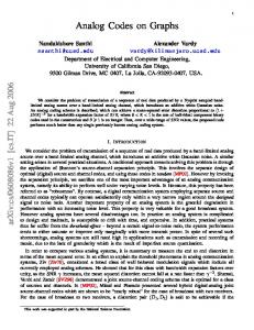
Figure 5. Internal structure of the PC-based STC for the modified Berger code C(16,5).
Figure 3. Internal structure of the T15 -based STC for the modified Berger code C(16,5).
The PC-based counter of 1's also has I = 15 information bits { X I , z2, . . . , 2 1 5 ) as inputs and, similarly to its T"based counterpart, it generates K = 4 complemented check bits directly (see Fig. 6). The remaining part of a circuit works in the same way as for the T"-based STC.
Any STC for the modified Berger code Cy16,5)has:
{z,z,q,q}
21 inputs: I = 16 information bits { q , x 2 , . . . , 2 1 6 ) and K = 5 check bits { s 4 , s 3 , s ~ , s 1 , s ~(s4 } is the most significant bit such that s4 = 216);and 155
As for the gate-level complexity of the two realizations considered, note the following. Assuming that: (i) a FA is built of 10 gates and (ii) the least complex known 15-input threshold circuit (obtained by modifying the least complex known 16-input SN from [20]) built of 56 comparators (i.e. 112 2-input gates) in 15 levels are used. The overall complexity of the T15-based counter of 1’s is 133 gates compared to 110 gates of the PC-based counter.
Table 1 presents the area and delay characteristics of the delay-optimized circuits. We have to note that the area estimations include the routing area. From Table 1 we can observe that when I is small ( I 5 IS), the SN-based circuit is slightly faster than its PC-based counterpart. However, for larger values of I (I > 16) the PC-based circuits are faster. It is also obvious that all SN-based circuits require much more area than the PC-based circuits. This is mainly because the SN-based circuits require much more area for their interconnections (approximately’75%of the total area is consumed by the interconnections).
Table 1. Delay-optimizeddesigns.
I
Circuit
1
Area [mm2]
1
Delay [ns]
1
Figure 6. l&input parallel counter. Table 2. Area-optimized designs.
Figure 7.5-pair TSC comparator. Table 3. Power estimation.
The 5-pair 2-rail TSC comparator, which could be built using four identical TSC 2-pair 2-rail modules as shown in Fig. 7, is identical for either version of a counter of 1’s.
4 Experimental Results We have described in structural HDL language PC-based and SN-based STCs for the following modified Berger C;16,5),c i 3 2 , 6 ) , and C;64,,). We use the codes: Design Analyzer tool by Synopsys to map each one of the above circuits to the 0.6pm CMOS VLSI implementation technology and then proceed to optimizations. At first we target speed. We repetitively synthesize each one of the circuits until no faster design can be obtained. We then recover as much area as possible without affecting the delay.
Since there are several applications where area is more critical than delay, we repeated the synthesis process targeting low area. From Table 2 one can derive similar observations as before: the PC-based designs are not only smaller than the SN-based designs but are also faster for larger I . 156
For comparing the power dissipation of two circuits, one must assume that they have the same clock frequency f. Hence, the two circuits should be optimized in such a way that they have approximately the same delay which corresponds to that frequency (further delay optimizations would be meaningless since the operating clock frequency is fixed). To this end, assuming a system clock of 333, 200, 133 and 100 MHz for the circuits with I = 8, 16, 32, and 64 respectively, we have optimized the SN-based and PCbased circuits so as their delays to be less than 3.0,5.0, 7.5 and 10.0 ns, respectively, and proceeded to power estimation. The results regarding area, delay and power dissipation are given in Table 3. It is evident that the SN-based circuits consume much more power than the equivalent PCbased circuits.
unordered codes,” in Dig.,Pap. 20th Int. FTC Symp., Newcastle upon Tyne, UK, June 26-28, 1990, pp. 457-464. [7] -, Design of Self-Testing Checkersfor Unidirectional Error Detecting Codes, Scientific Papers of the Inst. of Techn. Cybem. of the Techn. Univ. of Wrociaw, No. 92, Ser.: Monographs No. 24, Oficyna Wyd. Polit. Wroci., Wroclaw 1995, 112 pp. [8] -, ”Design of encoders and self-testing checkers for some systematic unidirectional error detecting codes,” Int. J. on Microelectronic Sjlstems Integration, vol. 5, pp. 246-260, No. 4, 1997. [9] Yu-Yau Guo, Jien-Chung Lo, and Metra C., ”Fast and areatime efficient Berger code checkers,” Proc. 1997 IEEE Int. Symp. on DFT in VLSI Systems, pp. I 10-1 18. [lo] X. Kavousianos, D. Nikolos, G. Foukarakis, and T. Gnardellis, ”New efficient totally self-checking Berger code checkers,” Integration, The VLSl Journal, vol. 28, Issue 1, pp. 101-118, 1 Sep. 1999. [ 1 I] M. Favalli and C. Metra, ”Design of low-power CMOS tworail checkers,” Int. J. on Microelectronic Systems Integration,vol. 5, pp. 101-110, No. 2, 1997. [12] G. K. Yeap, Practical Low Power Digital VLSl Design, Kluwer Academic Publishers, Boston, 1997. [ 131 W. C. Carter and P. R. Schneider, ”Design of dynamically checked computers,” in Proc. IFIP Coni, Edinburgh, Scotland, Aug. 1968, pp. 878-883. [I41 D. A. Anderson and G. Metze, ”Design of totally selfchecking check circuits for m-out-of-n.codes,” IEEE Trans. Comput., vol. (2-22, pp. 263-269, Mar. 1973. [I51 J. M. Berger, ”A note on error detection codes for asymmetric binary channels,” hfornl. Contr, vol. 4, pp. 68-73, Mar. 1961. [16] S. J. Piestrak, ”Design method of a class of embedded combinational self-testing checkers for 2-rail codes,” IEEE Trans. Comput., vol. C-50, 2001. [ 171 --, ”The minimal test set for multi-output threshold circuits implemented as sorting networks,” IEEE Trans. Comput., vol. 42, pp. 700-712, June 1993. [ 181 K. E. Batcher, ”Sorting networks and their applications,” in Proc. 1968 SJCC - Spring Joint Coinputer Con&,AFIPS, vol. 32, 1968, pp. 307-314. [ 191 D. E. Knuth, The Art of Coinpurer Progratnming, Vol. Ill, Sorting and Searching, 2nd Ed., Reading, MA, AddisonWesley, 1973, ch. 5. [20] D. C. Van Voorhis, ”An economical construction for sorting networks,” in Proc. AFIPS NCC - Nat. Computer Con&, 1974, pp. 921-927. [21] S. J. Piestrak and A. Dandache, ”Minimal test set for multioutput threshold circuits implemented as bubble sorting networks,” Electr. Lett., vol. 36, pp. 202-204, No. 3,2000. [22] S. J. Piestrak, ”Comments on ’Novel totally self-checking Berger checker designs based on generalized Berger code partitioning’,’’subm. in Jan. 1999 to IEEE Trans. Comput. [23] T. R. N. Rao et al., ”Novel totally self-checking Berger checker designs based on generalized Berger code partitioning,” IEEE Trans. Comput., vol. 42, pp. 1020-1024, Aug. 1993.
5 Conclusions We have considered real implementations of the selftesting checkers (STCs) for modified Berger codes with I = 2 K - 1 information bits. The simulation results of dynamic power dissipation for the two versions performed using power estimation CAD tools by Synopsys provided very interesting results. They revealed that the PC-based structures are more advantageous for designing STCs, since they are smaller, faster (when the size of the information part is medium or large), and consume less power than the structures built using sorting networks.
6
Acknowledgement
The authors would like to thank Prof. D. Nikolos for the fruitfull discussions concerning the presented work.
References [ 13 D. Lamer, ”Sun flips bits in chips,” Electronics Times, No.
878, p. 72 and 24, 10 Nov. 1997. [2] M. J. Ashjaee and S. M. Reddy, ”On totally self-checking checkers for separable codes,” IEEE Trans. Cornput., vol. C-26, pp. 737-744, Aug. 1977. [3] M. A. Marouf and A. D. Friedman, ”Design of selfchecking checkers for Berger codes,” in Dig., Pap. 8th Int. FTC Sytnp., Toulouse, France, June 1978, pp. 179-184. [4] S. J. Piestrak, ”Design of fast self-testing checkers for Berger codes,” IEEE Trans. Cotput., vol. C-36, pp. 629634, May 1987. [5] J.-Ch. Lo and S. Thanawastien, ”The design of fast totally self-checking Berger code checkers,” in Dig., Pap. I8th Int. FTC Symp., Tokyo, Japan, June 1988, pp. 226-231. 161 S . J. Piestrak, ”The minimal test set for sorting networks and the use of sorting networks in self-testing checkers for 157