Since the di are sorted by definition, we simply perform an insertion sort of the remaining N + 1 elements. 3. Implementation. A typical reconstruction process ...
Online 3D reconstruction using Convex Optimization Gottfried Graber, Thomas Pock, Horst Bischof Institute for Computer Graphics and Vision Graz University of Technology {graber,pock,bischof}@icg.tugraz.at
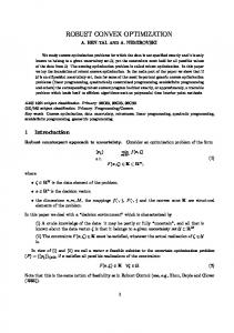
Abstract We present a system that is capable of interactively reconstructing a scene from a single live camera. We use a dense volumetric representation of the surface, which means there are no constraints concerning the 3D-scene topology. Reconstruction is based on range image fusion using a total variation formulation, where the surface is represented implicitly by a signed distance function. The final 3D-model is obtained by minimizing a global convex energy and extracting the zero level-set of the solution. The whole reconstruction process is designed to be online. Users can constantly inspect the current reconstruction and adapt camera movement to get the desired amount of detail for specific parts of the reconstructed scene.
Figure 1: Our system is able to reconstruct full 3D geometry from a single handheld camera.
point features. Obtaining a full 3D reconstruction by making the map dense seems not to be feasible due to the computational complexity, although some interesting steps towards this direction have been made in [5]. The first dense, realtime-capable reconstruction approach is presented in [7], where a base mesh is generated from the sparse point features of the SLAM system, which is successively refined via dense depth information obtained from realtime variational optical flow [9]. Since the base mesh, once created, cannot be adapted arbitrarily (i.e. change topology), the method is inherently limited: concave objects (e.g. holes, overhangs etc.) are reconstructed only partially or not at all.
1. Introduction Reconstructing dense 3D-geometry from a single moving camera is one of the fundamental problems of computer vision. It consists of a number of sub-problems, which are challenging on their own: In order to reconstruct the scene a local coordinate system needs to be established and one needs to know the camera pose as the camera explores the scene. This gives rise to the classical chicken-egg problem addressed by SLAM (simultaneous localization and mapping): In order to determine the camera pose, one needs to know how the world looks like (mapping), vice-versa one needs to know the camera pose to construct the map. SLAM aims to solve these problems simultaneously. Realtime SLAM has been an active research area for years and has recently seen great progress. While in the pioneering work of [3] the authors use a statistical approach (Extended Kalman Filter), current state of the art systems [4] employ a geometric approach (Bundle Adjustment). In the latter work, the authors split the tracking and mapping tasks into distinct threads, thus making effective use of the nowubiquitous multi-core CPUs. The resulting system is called PTAM (Parallel Tracking and Mapping). The map maintained by such realtime systems typically consists of sparse
In [8] the authors use multiple images from the PTAM framework to compute robust depth maps in realtime via variational optical flow. The resulting geometry is limited to 2.5D, since an integration/fusion of multiple depthmaps is not addressed in the work. In this work, we go beyond the aforementioned limitations towards a full 3D-reconstruction as depicted in figure 1. We propose a system that uses state-of-the-art realtime tracking, GPU based depthmap generation and high quality depth map fusion [11] [10] in a realtime environment. Reconstruction is based on an energy minimization which can be efficiently computed on the GPU. As the camera explores the scene, data is added continuously to the reconstruction algorithm, and the user can constantly review the current reconstruction result. Due to the iterative nature of 1
the reconstruction algorithm, an initial time period of about 45 seconds is required until the reconstruction result shows something meaningful. Afterwards the delay between camera movement and corresponding reconstruction decreases drastically, which results in a fairly interactive application.
Surface
Camera
line−of−sight x r(x) i
wi +1 0
fi
2. Method We use parallel tracking and mapping (PTAM) [4] for obtaining high quality camera pose estimates. PTAM splits tracking and mapping into two threads that run in parallel on two cores of the CPU. Following this idea, we introduce a third thread which is responsible for computing the 3D model. Since we use the tracking system merely for obtaining camera poses, coupling between the tracking and reconstruction threads is very loose. We do not rely on any assumptions regarding the tracking system, in particular our approach is independent of the map features used by the tracker. Thus the tracking system can easily be replaced by more powerful and accurate systems in the future.
−1 η
δ
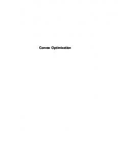
(a) Schematic illustration of the generation of distance fields
2.1. Depthmap Generation PTAM stores a list of keyframes, for which high quality camera pose estimates are computed via bundle adjustment. We use keyframes exclusively for generating depthmaps of the scene using a simple dense stereo algorithm. Camera pose estimates of the live tracking thread, although accurate enough for AR applications, have shown to be inferior for computing depthmaps. Whenever keyframes are added, depthmap generation is triggered in the reconstruction thread. We implemented a multiview version of the well known planesweep algorithm [2] using standard normalized cross correlation on the GPU. Additionally, we discard depth values with a correlation value below a threshold in order to get the most reliable depth hypotheses only.
(b) For every pixel of the depthmap the line-of-sight (blue) and a 3D-point according to the depth value are computed. The center voxel containing the 3D-point (purple) gets assigned distance value 0. Starting at the center voxel, voxels along the line-of-sight are assigned values towards -1 (farther away from the camera position) and +1 (towards the camera position) respectively. Projections onto the xz, yz and xy plane are shown for improved clarity.
Figure 2: Generation of distance fields f ergy functional (Z |∇u| + λ
min
2.2. Depth Map Fusion We use a volume based reconstruction similar to [11] [10]. The 3D-surface is represented implicitly as the zero level-set of a function u : Ω → [−1, 1], where Ω is a subset of R3 . First, depthmaps are converted to truncated signed distance fields f (see figure 2) and for memory reasons compressed into a histogram representation. Instead of storing the volumetric representation of f directly, the interval [−1, 1] is sampled at evenly spaced discrete positions di , i = 1 . . . N and the exact value of every voxel of f is replaced by the nearest di . Thus, we can store an arbitrary number of distance fields f using a “volume histogram” consisting of N bins. We denote by h(x, i) the histogram count of bin i, i.e. how often the value di occurred in the distance fields f at voxel x. Depth map fusion is done by minimizing a convex en-
u
Ω
N Z X i=1
) h(x, i)|u(x) − di |dx
(1)
Ω
The first term (regularization term) measures the total variation of the function u. It is used to minimize the surface area of the level sets and hence effectively removes noise caused by the outliers of the depth maps. Note that the total variation independently minimizes the surface area of each level set of the function u, that is, the surface of the final 3D model. The second term measures the `1 distance of the solution to the individual distance fields generated from the depth maps. In [10], the authors approximately minimize (1) by splitting the data and the regularization term and then performing an alternating minimization of easier subproblems. Here, we propose to use the recently introduced first-order primal-dual algorithm [1]. The advantage is that we can directly minimize (1) without performing any approximation.
The primal-dual formulation of (1) is given by ( Z ) N Z X min max − u div p + λ h(x, i)|u(x) − di |dx , u
kpk∞ ≤1
Ω
i=1
Ω
(2) where p : Ω → R3 is the dual variable. The algorithm consists of alternatingly performing gradient descend steps in u and gradient ascend steps in p. ( un+1 = proxhist (un − τ (−div pn )) � pn+1 = projkpk∞ ≤1 pn + σ∇(2un+1 − un ) , (3) where τ, σ > 0 are the primal and dual steps. Convergence is shown in [1] for τ σkdivk2 < 1. The function projkpk∞ ≤1 (·) defines a point-wise projection of the dual variable onto the unit ball. The projection of a vector q(x) at a position x onto the unit ball is given by the following explicit formula projkqk∞ ≤1 (q(x)) =
q(x) . max{1, kq(x)k}
The function proxhist (·) is the proximal operator with respect to the data term. Its solution is given by minimizing a quadratic distance term plus the histogram term. Since the histogram term is defined pointwise, the proximal operator is given by the solution of pointwise minimization problems. Given a number v(x), the solution of the proximal operator at a point x is defined as proxhist (v(x)) = ( ) N X ku − v(x)k2 arg min +λ h(x, i)|u − di | u 2τ i=1
(4)
In [6], it is shown that the global minimizer of the above problem can be computed via a generalized shrinkage formula. It is given by proxhist (v) = median {d1 , ..., dN , p0 , ...., pN } where di are the distances related to the according histogram bin i and the pi , i = 1...N are computed as pi = v + τ λWi ,
Wi = −
i X j=1
h(x, j) +
N X
h(x, j)
j=i+1
Computing the median requires sorting a sequence of 2N + 1 elements. Since the di are sorted by definition, we simply perform an insertion sort of the remaining N + 1 elements.
3. Implementation A typical reconstruction process starts with the user initializing the tracking system. Afterwards the volume of interest is specified.
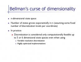
Figure 3: Communication between the SLAM and reconstruction threads via a queue of workload items. After setting up the volume, the rest of the reconstruction pipeline is fully automated: Whenever a keyframe is added to the map, the reconstruction thread is notified and executes a “workload item” consisting of the following steps: Generate depthmap, generate distance field and run a fixed number of iterations. Which keyframes to use for reconstruction is decided upon the percentage of viewing rays intersecting the volume, that is, the percentage of image pixels whose 3D points potentially lie inside the volume. A workload item consists of the actual keyframe, neighboring keyframes that should be used for depthmap generation and the corresponding camera poses. Hence we use a simple queue of workload items for inter-thread communication between the SLAM system and the reconstruction thread (see figure 3). Visual feedback on the queue status is provided through the GUI. The amount of time needed to process a workload item strongly depends on the number of iterations associated with that item. From our experiments, a value of 3-6 iterations is a good tradeoff between processing time and progression of the minimization algorithm. At this setting, the rate of keyframe generation nicely matches the rate of workload item processing, i.e. the queue length rarely exceeds a value of two. On a GTX480, typical timings for the individual steps are 1000ms for depthmap generation (4 views), 20ms for distance field generation & histogram update and 360ms for the minimization algorithm (4 iterations) . We noticed that especially the computation of the median (insertion sort) greatly profits from the improved caching architecture of the nvidia GeForce 400 series. On an older GT200b (Tesla) series card, minimization runs significantly slower. Since the reconstruction result changes each time a workload item has been processed, a full recalculation of a triangle-based mesh, texturing etc. seems unfeasible for online visualization. We therefore use the implicit representation of the surface directly and implemented a GPUbased raycaster which is capable of rendering level sets of u, including simple shading based on surface normals and texture information. Texturing works by calculating a grayvalue for each voxel based on keyframe image data: For a virtual camera pose (i.e. the camera pose of the raycaster rendering the reconstructed geometry) we determine the 5 closest keyframes. Each voxel is projected into these
keyframes and we take the median of the grayvalues as texture information for the voxel. This approach obviously produces artifacts as the distance between the virtual camera and the closest keyframe gets bigger, but the visual results are adequate. An integration of a mesh-based approach including high quality texturing is planned for future work.
4. Results
(a)
(b)
(c)
(d)
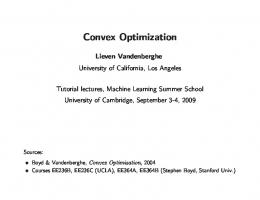
Figure 4 depicts some results of system. For this scene the camera was moved two times around the object. The time for the whole process was approximately two minutes. Note the accurate reconstruction of details and the true 3D geometry of the triumphant arch.
References [1] A. Chambolle and T. Pock. A first-order primal-dual algorithm for convex problems with applications to imaging. J. Math. Imaging Vis., 40:120–145, May 2011. 2, 3 [2] R. Collins. A space-sweep approach to true multi-image matching. In IEEE Computer Vision and Pattern Recognition, pages 358–363, June 1996. 2 [3] A. J. Davison. Real-time simultaneous localisation and mapping with a single camera. In Proceedings of the Ninth IEEE International Conference on Computer Vision - Volume 2, ICCV ’03, pages 1403–, Washington, DC, USA, 2003. IEEE Computer Society. 1 [4] G. Klein and D. Murray. Parallel Tracking and Mapping for Small AR Workspaces. 2007 6th IEEE and ACM International Symposium on Mixed and Augmented Reality, pages 1–10, Nov. 2007. 1, 2 [5] G. Klein and D. Murray. Improving the agility of keyframebased SLAM. In Proc. 10th European Conference on Computer Vision (ECCV’08), pages 802–815, Marseille, October 2008. 1 [6] Y. Li and S. Osher. A new median formula with applications to pde based denoising. Communications in Mathematical Sciences, 7(3):741–753, 2009. 3 [7] R. A. Newcombe and A. J. Davison. Live dense reconstruction with a single moving camera. In IEEE Conference on Computer Vision and pattern Recognition, 2010. 1 [8] J. Stuehmer, S. Gumhold, and D. Cremers. Real-time dense geometry from a handheld camera. In Pattern Recognition (Proc. DAGM), pages 11–20, Darmstadt, Germany, September 2010. 1 [9] M. Werlberger, W. Trobin, T. Pock, A. Wedel, D. Cremers, and H. Bischof. Anisotropic Huber-L1 optical flow. In Proceedings of the British Machine Vision Conference (BMVC), London, UK, September 2009. 1 [10] C. Zach. Fast and high quality fusion of depth maps. Proc. 3DPVT, 2008. 1, 2 [11] C. Zach, T. Pock, and H. Bischof. A globally optimal algorithm for robust tv-l1 range image integration. In ICCV, pages 1–8. IEEE, 2007. 1, 2
(e)
(f)
(g)
(h)
(i)
(j)
(k)
(l)
Figure 4: 4a-4d: Some input images, 4e - 4h: preliminary results during the reconstruction process 4i,4j: reconstruction result without texture, 4k,4l: reconstruction result with texture mapping. Volume resolution: 448 × 320 × 192